Ceridian Dayforce Tuff Clock User manual

Ceridian’s
Dayforce Tuff Clock
User Manual [ENG]
WARNING: This manual contains information on limitations regarding product use,
function and information on the limitation and liability of the manufacturer. Read the
entire manual carefully.
rev 2Jul2018.

DF Tuff
Page 2 of 31
Read and save these instructions! Follow all warnings and instructions
specified within this document and/or on the equipment. Always
ensure you obtain the latest version of the User Guide. Updated
versions of this User Guide are available by contacting your Ceridian
HCM administrator.
1IMPORTANT SAFETY INSTRUCTIONS
To reduce the risk of fire, electric shock and/or injury, observe the
following safety precautions:
•Do not attempt to service this product yourself. Opening or
removing the cover may expose you to dangerous voltage or
other risk. Refer servicing to qualified service personnel. Never
open the device yourself.
•Do not touch the equipment and its connected cables during an
electrical storm; there may be a risk of electric shock.
2REGULAR MAINTENANCE AND TROUBLESHOOTING
Keep your DF Tuff Clock in optimal condition by following all the
instructions that are included within this manual and/or marked on the
product.
3HANDLING PRECAUTIONS
•Do not subject the touchscreen to mechanical shock (e.g.,
dropping or striking). Mechanical shock could damage the glass
display.
•If the touchscreen glass is damaged, the liquid crystal fluid
inside could leak out. Avoid contact with the liquid crystal fluid.
If the liquid crystal fluid comes into contact with your skin or
clothes, promptly wash it off using soap and water.

DF Tuff
Page 3 of 31
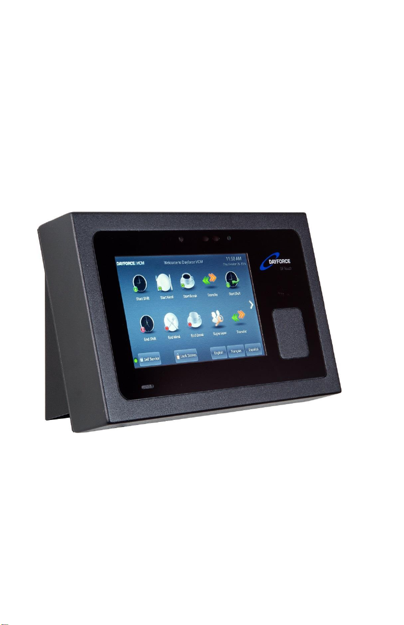
•Do not apply excessive force to the display surface or adjoining
areas. Excessive force will distort the image on the display.
•Do not use hard or sharp implements to operate the
touchscreen. Operating the touch screen with implements
harder than a finger could scratch the display.
•Do not attempt to disassemble the Unit.
4CLEANING
If the display surface is contaminated, moisten a soft cloth with
isopropyl alcohol to clean it. Other cleaners such as ketone (e.g.,
acetone), and/or aromatic solvents (e.g., benzene and toluene) may
damage the display. Do not use abrasives, thinners, solvents or aerosol
cleaners (i.e., spray polish).
The equipment has been designed to withstand light water spray. As
long as waterproof connectors are used for all cable connections the
equipment may be washed down.
WARNING: This equipment shall be installed and used within an
environment that provides the pollution degree max 2 and over-
voltages category II non-hazardous locations, indoor only. It is designed
to be installed, serviced and/or repaired by service persons only [service
person is defined as a person having the appropriate technical training
and experience necessary to be aware of the hazards to which a person
may be exposed in performing a task and of measures to minimize the
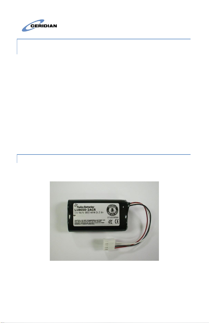
risks to other persons]. With the exception of the battery, the end user
cannot replace any of the parts within the unit. These safety
instructions should not prevent you from contacting the installer or
Dayforce HCM administrator to obtain any further clarification and/or
answers to your concerns.

DF Tuff
Page 4 of 31
5MAINTENANCE
With normal use, the system requires minimal maintenance. We
recommend, however, that the standby batteries be replaced every 3-5
years.
6SPECIFICATIONS
This document describes the technical specifications of the DF Touch
clock terminal.
6.1 Display and Keypad
Capacitive Touch, 7 inch, 800x480 pixels or better, hardened glass
surface.
6.2 Processor
CPU: 1GHz Dual Core ARM Cortex A9 or better.
RAM: Memory 1GByte 528 MHz SoDIMM, Non-volatile FLASH
memory 8GByte
6.3 Environment
Operating temperature: 0° to 40°C (32° to 105°F)
Storage temperature: -30° to 80°C (-22° to 176°F) [no battery]
Storage temperature: -20° to 50°C (-22° to 122°F) [with battery]
Humidity: 10% to 90% relative humidity, non condensing.
6.4 Power Supply
Input Power Jack:
24 VDC ±5%, 0.75 A, 18 W maximum
Power over Ethernet (PoE)

DF Tuff
Page 5 of 31
IEEE 802.3at Type2, absolute operating input voltage 42.5-57VDC,
nominal draw 10Watts, max 18Watts.
Optional: External power supply
Input voltage 110-250 VAC, 0.5 A, 50/60Hz
Optional: Battery backup
Discharge life: 1.5 hours at 23°C (73°F)
Charge time: 66Hrs (on first use)
Charging (normal): 0° to 45°C (32° to 113°F)
Storage: -20° to 50°C (-4° to 95°F)
Discharging (battery: -20° to 60°C (-4° to 140°F)
6.5 Operating System
Android 4.0.3 (ICS)
Android 6.0.1 (Marshmallow) –Available Q4 2018
6.6 Application Programs
Dayforce Clock Program
Dayforce Self Service
6.7 Enclosure and Wall-mount.
Enclosure: Aluminum and glass.
Wall-mount: Steel.
6.8 Network Connectivity
IEEE 802.3 10/100BASE-T/1000BASE-T Ethernet using TCP/IP
communication protocol and CAT-5 cable, cable lengths between
the terminal and an Ethernet network hub can be up to 328 wire-
feet.

DF Tuff
Page 6 of 31
DHCP (Dynamic Host Configuration Protocol) is implemented to
assign IP addresses for the terminal, host and router. Static IP
addresses may also be assigned manually via the touch screen.
The terminal supports the use of DNS servers to convert host
names to host IP addresses in both DHCP and static IP modes.
6.9 Camera
Integrated camera with 3 Megapixels resolution and torch flash
LEDs.
6.10 LED
Three-color LED (red, green, blue) for status display
6.11 External USB ports
One USB ports for Ceridian approved reader devices.
Optional second USB port (Factory installed option)..
6.12 Optional readers & Module (extra cost)
Proximity reader (125Khz or 13.56Mhz –for HID Proxpoint™,
iClass™, Mifare™, NFC –reading only non-proprietary codes)
6.13 Optional Relay Output and Digital Input
Two Form C relay outputs; 1A at 30V DC.
Two Optically Isolated Inputs; 24V DC, 1.2Kohm
6.14 Certifications
CE Mark, FCC Part 15 Class A
6.15 Time Synchronization

DF Tuff
Page 7 of 31
Terminal uses a web service to synchronize its time with
Dayforce servers.
6.16 Dimensions (Approximate)
11 in (28cm) wide
6.75 in (17cm) high
4.5 in (7.5cm) deep including angled wall-mount
Weight about 4.4 lbs (2Kg) with packaging
7BATTERY PACK INSTALLATION INSTRUCTIONS
Disclaimer: These instructions are for battery pack model L18650-2ACR,
manufactured by Fedco Batteries. Use of any other battery is not covered by
this document is potentially hazardous and will void the Dayforce Clock
warranty.
7.1 L18650-2ACR Battery Instructions
This product may be supplied with a rechargeable Lithium Ion battery.
The following are important safety instructions for using, storing, and
disposing of the battery.
7.1.1 Disposal for Li-Ion Battery Pack
The rechargeable battery contains the following components that must
be disposed of in accordance with local regulations: Lithium Ion cells.
Caution: When the battery is worn out, insulate the connector terminals
with adhesive tape or similar material before disposal.
Misuse or improper disposal of the battery pack may cause the battery
to become very hot, ignite, or explode. When disposing of a battery
pack, contact your local waste disposal service provider regarding local
restrictions on the disposal and recycling of batteries.

DF Tuff
Page 8 of 31
7.1.2 Storage and Safety Information for the L18650-2ACR
Battery
Do not crush, puncture, incinerate, short-circuit, disassemble, immerse
in water, expose to strong mineral oxides, or heat the battery over 60
degrees Celsius. Exposure to battery contents may be harmful. In case
of eye exposure, flush with water for 15 minutes without rubbing and
seek medical attention. In the case of skin exposures, wash affected
area with liberal amounts of water for at least 15 minutes and seek
medical attention.
When not in use, store batteries between -20 degrees Celsius and 35
degrees Celsius. In case of fire, use CO2, dry chemical powder, or
alcohol resistant foam extinguishers.
7.1.3 Installing or Removing the L18650-2ACR Battery
The L18650-2ACR Battery resembles the figure below:
L18650-2ACR Battery Pack
The battery kit that comes with the clock includes the battery, the
battery cover, the battery cable, and two screws, as shown in the
following image:

DF Tuff
Page 9 of 31
Battery kit
Remove the screws on the rear of the chassis, and gently flip back the
rear cover so that the inside of the clock is accessible.
Step 1: Place the battery between the two battery clips and secure using
#4-40 screws through the two middle holes on both sides. See Figure B1
and B2.

DF Tuff
Page 10 of 31
Figure B1: Battery clip assembly.
Figure B2: Securing battery into the battery clip assembly.
Step 2: Secure battery assembly to mounting posts using four #4-40
screws. Use the four corner holes.

DF Tuff
Page 11 of 31
Step 3: Attach battery extension cable to battery as shown in Figure B3.
Ensure connectors are attached in the correct orientation.
Figure B3: Attaching battery extension cable to battery.
Step 4: Attach battery extension cable to main circuit board as shown in
Figure B5. Ensure that the connectors are attached in the correct
orientation.

DF Tuff
Page 12 of 31
Figure B5: Attaching battery extension cable to main circuit board.
Figure B6: Battery installed in clock.

DF Tuff
Page 13 of 31
Step 5: Gently flip the rear cover back onto the rear of the enclosure,
carefully to fold the wires back into the enclosure without pinching
them. Secure the rear cover by installing the screws to hold the cover in
place.
7.2 Charge the Battery
Batteries are shipped uncharged. An uncharged battery must be
charged for a period of 66 hours before it will become fully charged,
‘formed’ for maximum life, and available for backup power use.
Power the unit from the AC/DC wall adapter or PoE. The Battery will
commence charging.
New clocks will automatically form the batteries. The forming procedure
will fully charge the battery over a period of about 24 hours, then allow
it to discharge before charging it again and repeat this until 3 cycles
have been completed. If a battery is replaced, you can initiate the
battery forming sequence manually by using the administrative function
provided. The clock is fully functional during the forming process
Notes:
1. A system running on battery power can be shut down by pressing
the reset button which is located alongside the rear connectors.
2. If operation on battery power is attempted before the battery
reaches full charge, there may be insufficient voltage to transition
to battery powered operation and the system will stop operating.
Place the system back on AC/DC wall adapter or PoE power. Press
the reset button if necessary to shut it down.
8CAMERA USE APPLICATION NOTES
The following best practices are recommended for recording punches
using camera validation:

DF Tuff
Page 14 of 31
•The puncher’s face should be well lit and be between 18 and 30
inches from the camera lens (which is on the top center of the
screen).
•There should not be any other faces in the view of the camera
because the software will then not be able to decide which face
to capture.
•There should not be a lot of movement behind the puncher. For
this reason, the clock should not be mounted in busy areas if
the camera function is to be used.
•There should not be a light source in the camera’s view.
There are two camera validation options:
•Face detection and capture: The clock captures an image of the
user’s face saves it in the client’s instance so that it can then
optionally be viewed on the timesheet. This option uses a great
deal of data storage.
•Facial recognition: Employees are enrolled for verification (i.e.,
their image is taken, saved, and distributed to clocks). When
employees punch, the clock attempts to validate that the image
it sees corresponds to the saved image.
The estimated punch rate when using camera validation should be
between 1 and 6 per minute depending on the option selected.
9INSTALLATION INSTRUCTIONS
The DF Touch Clock has two parts: the clock and the wall-mount. The
Clock is shipped in a cardboard carton together with the wall-mount, a
5ft Ethernet cable, and the external power supply.
9.1 Installing the wall-mount
Install the clock in areas that are well lit and not exposed to very hot,
cold or damp conditions. Install the wall-mount exactly horizontally.
Enclosed in the box, you will find the following:

DF Tuff
Page 15 of 31
Figure 1: Box contents
•The wall-mount.
•Four screws (#6-32 x 3/8in Philips, for position ‘C’ in Figure 1),
and a self-adhesive cable tie for dressing the cables behind the
clock if desired.
•The power cable and its plug.
•The network cable.
•Optional: The relay output/input connectors which are only
included if you have ordered the relay option.

DF Tuff
Page 16 of 31
Figure 2: Wall-mount
Use the holes marked B in Figure 2 to attach the wall-mount to a
standard NEMA electrical box, or the holes marked A to mount the clock
to a wall.
The recommended height for mounting the clock differs depending on
your organization’s needs:
•To accommodate users in wheelchairs, install the wall-mount
with its top edge 48 inches from the ground.
•If the camera feature will be used, or if wheelchair access is not
required, install the wall mount with its top edge 56 inches from
the ground.
If the wall-mount is attached to an electrical box, feed the low-voltage
power cable and network cable through the wall, into the box, and
through the cut-out opening of the wall-mount.

DF Tuff
Page 17 of 31
9.2 Connecting and attaching the clock
Note the position of the various connectors on the rear of the clock in
Figure 3. The 2nd USB and Relay Output/Input are factory options and
may not appear on your clock.
Figure 3: Rear view of the clock and connections
Mount the clock to the wall-mount using the (4) supplied screws as in
Figure 4. Connect the necessary cables; External Power, Network, etc.
The enclosed cable-tie may be used as desired to coil and dress any
wires up behind the clock.

DF Tuff
Page 18 of 31
Figure 4: Mounted Clock with cables connected

DF Tuff
Page 19 of 31
9.3 Note re Power Supply
Clocks are supplied with an external low current power pack which
delivers 24V DC and plugs directly into the 4-pin Power Input connector
on the rear of the unit (Binder Part Number 09 3431 116 0415). The pin
assignments are shown in Figure 5.
Figure 5: Power Input Pinouts
The provided power supply comes with a mating connector, which
when properly installed provides a measure of water-splash resistance.
The mating connector is a Binder Part Number 99 0430 14 04. Its wiring
guide is shown in Figure 6.
Figure 6: Power Input mating-connector pinouts

DF Tuff
Page 20 of 31
The external power pack need not be connected when Power over
Ethernet (PoE) is available from the Ethernet switch.
Table of contents
Other Ceridian Clock manuals