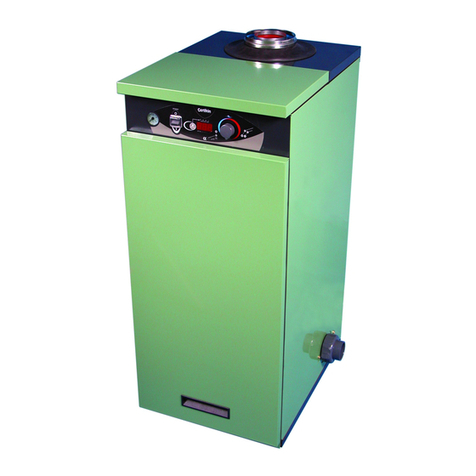
Certikin MB055 User guide

M3556 Rev B
MB055 MB105 MB155
WARNING: If the information in these instructions are not followed exactly, a fire
or explosion may result causing property damage, personal injury or death.
Do not store or use gasoline or other flammable vapours and liquids in the vicinity of
this or any other appliance.
WHAT TO DO IF YOU SMELL GAS
• Do not try to light any appliance.
• Do not touch any electrical switch; do not use any phone in your building.
• Immediately call your gas supplier from a neighbour's phone. Follow the gas sup-
plier's instructions.
Installation and service must be performed by a Gas Safe registered installer, service
agency or the gas supplier.
Operating, Installation and Servicing Instructions for
Direct fired swimming pool & spa heaters
Models: MB055, MB105, MB155, MB185, MB265, MB405
MB185
MB265
MB405

U.K. & Europe Table A .
PERFORMANCE SPECIFICATIONS - NATURAL GAS
GAS CATEGORY, TYPE AND SUPPLY PRESSURE II2H3+ G20 @ 20 mbar (8 in. wg)
MODEL 055 105 155 185 265 405
Corgi Work Code 1014357 1014358 1014359 1014360 1014361 1014362
BURNER mbar 6.3 6.8 7.7 8.1 8.3 8.7
PRESSURE
HEAT GROSS kW 12.9 26.67 38.98 49.53 71.5 108.4
INPUT (Btu/h) (44,000) (91,000) (133,000) (169,000) (244,000) (370,000)
NET kW 11.6 24.0 35.08 44.58 64.4 97.6
(Btu/h) (39,600) (81,900) (119,700) (152,100) (219,600) (333,000)
HEAT kW 10.06 20.8 30.4 38.63 55.8 84.58
OUTPUT (Btu/h) (34,300) (71,000) (103,700) (131,820) (190,300) (288,600)
GAS RATE m
3/h 1.22 2.5 3.7 4.6 6.6 10.28
INJECTOR DIA. mm 1.78 1.78 1.85 1.78 1.78 1.78
& (MARKING) gauge (50) (50) (49) (50) (50) (50)
NUMBER OF BURNERS 4 8 10 13 19 29
& INJECTORS
PERFORMANCE SPECIFICATIONS - LPG
GAS CATEGORY, TYPE AND SUPPLY PRESSURE II2H3+ G30 @ 30 mbar, G31 @ 37 mbar
MODEL 055 105 155 185 265 405
Corgi Work Code 1014374 1014375 1014376 1014377 1014378 1014379
HEAT GROSS kW 14.65 12.9 26.67 38.98 49.53 71.5 108.4
INPUT (Btu/h) (50,000) (44,000) (91,000) (133,000) (169,000) (244,000) (370,000)
NET kW 13.2 11.9 24.54 35.86 45.57 65.8 99.8
(Btu/h) (45,000) (40,500) (83,720) (122,360) (155,480) (224,480) (340,400)
HEAT kW 11.0 10.06 20.8 30.4 38.63 55.8 84.58
OUTPUT (Btu/h) (37,400) (34,300) (71,000) (103,700) (131,820) (190,300) (288,600)
GAS RATE m
3/h 0.50 0.47 0.97 1.43 1.82 2.57 4.04
INJECTOR DIA. mm 1.01 0.99 0.99 1.01 1.01 1.01 1.01
& (MARKING) gauge (60) (61) (61) (60) (60) (60) (60)
NUMBER OF BURNERS 4 4 8 10 13 19 29
& INJECTORS
055
Easiheat
GENERAL SPECIFICATIONS
WATER CONTENT Litre Model 0.8 Model 1.1 Model 1.8
(gal) 055 (0.18) 105 (0.3) 155 (0.4)
Model 1.9 Model 1.9 Model 2.6
185 (0.4) 265 (0.4) 405 (0.5)
MAXIMUM WATER PRESSURE 8 bar (125 psi)
MAXIMUM WATER FLOW TEMP 45.0 °C 110 (°F)
ELECTRICAL SUPPLY 230V 50Hz, FUSED AT 3A. POWER 100W
EASIHEAT NOTE: The Easiheat will use about 1kg of Propane for every hour of continious running.

1MB Pool & spa heater
INSIDE COVER - GENERAL & PERFORMANCE SPECIFICATIONS
2 PART ONE - USER'S OPERATING INSTRUCTIONS
2 Start-up procedures
2 Safety before start-up
3 Operating models 055, 105 and 155
4 Operating models 185, 265 and 405
5 Caution notice
5 Maintenance and care procedure
6 Pool & spa water chemistry
6 Cold weather operation
6 Winterizing the pool & spa heater
PART TWO - INSTALLATION/SERVICE INSTRUCTIONS
7 General notices
INSTALLATION INSTRUCTIONS
7 Installation of the pool & spa heater
11 Outdoor heaters
11 Indoor heaters
14 Combustion air
15 Gas supply connections
16 Plumbing for water connections
16 Left side water connection conversion
19 Electrical wiring
SERVICING INSTRUCTIONS
22 General location of controls
24 Temperature controls
25 Pressure switch
26 High limit
26 Pilot safety
26 Burner drawer removal
26 Gas valve removal
26 Main burner & orifice removal
26 Pilot removal & cleaning
27 Heat exchanger removal
27 Control immersion well replacement
27 Tube cleaning
28 Desooting procedure
28 Combustion chamber removal
28 Unitherm governor replacement
TROUBLE SHOOTING GUIDE
29 Mechanical - All models
32 Electrical models 055, 105 & 155.
34 Electrical models 185, 265 & 405.
REPLACEMENT PARTS
36 Replacement parts list - 055
38 Replacement parts list - 105
40 Replacement parts list - 155
42 Replacement parts list - 185, 265 & 405
Contents

2MB Pool & spa heater
PART ONE - USER'S OPERATING INSTRUCTIONS
FOR YOUR SAFETY - READ BEFORE OPERATING
WARNING: IF YOU DO NOT FOLLOW THESE INSTRUCTIONS
EXACTLY, A FIRE OR EXPLOSION MAY RESULT, CAUSING
PROPERTY DAMAGE, PERSONAL INJURY OR LOSS OF LIFE.
START-UP PROCEDURES
BEFORE START-UP
BURNERS
Clean air louvres of dust, lint and debris. Keep
heater area clear and free from combustibles, flam-
mable liquids and chemicals. Do not obstruct the
flow of combustion and ventilating air.
WATER
Water must be flowing through the heater during
operation. Ensure that system is filled with water
and the pump is operating.
055 105
155 185 - 265 - 405

3MB Pool & spa heater
CAUTION: Propane gas is heavier than air
and will settle on the ground. Since propane
can accumulate in confined areas, extra care
should be exercised when lighting propane
heaters.
FOR YOUR SAFETY READ BEFORE OPERATING
WARNING: IF YOU DO NOT FOLLOW THESE INSTRUCTIONS EXACTLY, A FIRE OR EXPLOSION MAY
RESULT CAUSING PROPERTY DAMAGE, PERSONAL INJURY OR LOSS OF LIFE.
This appliance is equipped with an ignition device
which automatically lights the pilot. Do not try to light
the pilot by hand.
BEFORE OPERATING after a prolonged off, smell all
around the appliance area for gas. Be sure to smell next
to the floor because some gas is heavier than air and
will settle on the floor.
* WHAT TO DO IF YOU SMELL GAS
* Do not try to light any appliance
* Do not touch any electric switch
* Do not use any phone in your building.
* Immediately call your gas supplier
from a neighbour's phone. Follow the
gas supplier's instructions.
* If you cannot reach your gas supplier,
call the fire service.
Isolate the appliance with the Service Cock inside. If
this is not accessible, isolate at the gas meter.
Do not use this appliance if any part has been
under water. Immediately call a qualified
service engineer to inspect the appliance and
to replace any part of the control system and
any gas control which has been under water.
OPERATING MODELS
055,105 and 155
Quick Start
Check that the Electricity and Gas Supplies are
on. Turn on the Pool Pump. Turn on the Heater
with the switch on the Front Panel and set the
desired temperature with the Pool Temperature
Knob. In a few seconds the Heater will fire.
Summary of Controls (Left to Right)
Pool Temperature Control Knob
16°C to 41°C (60°F to 106°F)
The Pool or Spa water temperature is controlled
by the Pool Temperature Knob, rotate anti-
clockwise to increase the Pool Temperature.
The Knob is fitted with a means of limiting the
uppertemperaturelimitbelowthemaximumlevel.
The knob stop adjustment ring illustrated is ad-
justable by loosening the set screw, rotating the
knobstop ring to the desired location and retight-
ening the set screw.
High Limit
If the Heater temperature rises too high the
High Limit Thermostat will operate. Wait until
the Heater is cool then press 'Reset'. It will click
if it has had to reset. The Heater should now
run.
If this problem persists this should be investi-
gated by a Service Engineer.
ON/OFF Switch - Turns the Heater On and Off
and resets the Ignition Control if locked out. For
longer periods of isolation the Heater should be
switched off at its Mains supply.
Knobstop Ring
Pool Temperature Range
Spa Temperature
Range
Standby
Temperature
kstop.tif

4MB Pool & spa heater
Quick Start
Check that the Electricity and Gas Supplies are on.
Turn on the Pool Pump. Turn on the Heater with the
switch on the Front Panel and set the desired tem-
perature with the Pool Temperature Knob. In a few
seconds the Heater will fire.
Summary of Controls (Left to Right)
ON/OFF Switch - Turns the Heater On and Off and
resets the Ignition Control if locked out.
Lock/Unlock Button - If it is pressed for 2
seconds it locks the Set Temperature so the Pool
Temperature Knob is inoperative. To unlock, press
again for 2 seconds.
With a short press the Set temperature is displayed.
It will flash if the Lock is ON.
Pool Temperature Display - This normally shows
the Pool Temperature but also show the Setting
Temperature when the Pool Temperature Control
Knob is moved. The Display is also used for com-
missioning and diagnostic purposes. If the display
alternates the temperature with 'SEr' it is recom-
mended that the Heater is serviced, it will continue
to function. (Page 34)
Pool Demand LED - Green
Off - There is no Pool Heating demand, pool heating
is off.
On - There is Pool Heating Demand and the Pool is
not up to temperature.
Flashing - The Pool Heating Demand is met, the
pool is up to temperature.
Pool Temperature Control Knob
16°C to 32°C or 41°C (60°F to 90°F or 106°F)
(Maximum is changed in Setup Mode, see Page 34)
Rotate clockwise to increase the Pool Temperature.
The Setting Temperature is shown whilst rotating the
control knob and when released flashes 3 times to
confirm setting.
To lock the required Temperature Setting see
Lock/Unlock Button.
OPERATING MODELS 185, 265 and 405
Pool Filter Blocked - Yellow
On - If the pump is running and there is insuf-
ficient pressure, possibly due to a blocked Pool
Filter. The Heater will not run.
Overheat - Red
On - This indicates the Heater has overheated
and shutdown. Use the Overheat Reset (see
below). If this problem persists this should be
investigated by a Service Engineer.
Overheat Reset (not on front panel)
If the Overheat Indicator has lit the Heater will not
work until the thermostat has been reset.
(See page 24 for location)
Wait until the Heater is cool then remove the door
and locate the Overheat Thermostat mounted on
its bracket. Press its centre and it will click.
The Red Overheat indicator will go out and the
Heater can now run.

5MB Pool & spa heater
AFTER START-UP
Feel the inlet and outlet pipes. Outlet pipe should
be only slightly warmer than the inlet. It should not
be hot.
WARNING: Should overheating occur or the gas
supply fail to shut off, turn off the manual gas control
to the appliance.
VISUAL INSPECTION
With the heater on, remove the door and make a
visual check of the pilot and burner.
Theflameshouldbebluewithawell-definedpattern.
MAIN BURNER FLAME
PILOT BURNER FLAME
A yellow or "floating" flame indicates restricted air
openings or incorrect injector size. Should this
occur, shut the heater off and contact your installer
or gas supplier.
WATER PRESSURE SWITCH
A water pressure switch is provided in the heater
to shut off the burners in the event that water sup-
ply to the heater is interrupted. It is very important
to verify that the switch electrically opens and
shuts off the gas valve when water flow to the
heater is interrupted. Otherwise, rapid and severe
damage is likely to occur to the heater. (The water
pressure switch should be checked and adjusted
for proper operation by a qualified service person
at the time of installation checked thereafter.
WARNING: Operation of the heater without water
circulation will cause rapid and severe damage to
the heater.
CAUTION
Elevated water temperature can be hazardous, and
the U. S. Consumer Product Safety Commission
recommends the following guidelines:
1. Spa or hot tub water temperatures should
never exceed 40°C (104°F). A temperature of 38°C
(100°F) is considered safe for a healthy adult. Spe-
cial caution is suggested for young children.
2. Drinking of alcoholic beverages before or dur-
ing spa or hot tub use can cause drowsiness which
could lead to unconsciousness and subsequently
result in drowning.
3. Pregnant Women Beware! Soaking in water
over 39°C (102°F) can cause fetal damage dur-
ing the first three months of pregnancy resulting
in the birth of a brain-damaged or deformed child.
Pregnant women should stick to the 38°C (100°F)
maximum rule.
4. Before entering the spa or hot tub, users should
check the water temperature with an accurate
thermometer; spa or hot tub thermostats may be in
error in regulating water temperatures by as much
as 2°C (4°F).
5. Persons with a medical history of heart di
sease, circulatory problems, diabetes, or blood
pressure problems should obtain a physician's ad-
vice before using pools or hot tubs.
6. Persons taking medications which induce
drowsiness, such as tranquilizers, antihistamines, or
anticoagulant, should not use spas or hot tubs.
MAINTENANCE AND CARE
PROCEDURES
It is recommended that the Heater is serviced every
2000 hours of operation, for normal use this is about
12 months. The control will alert when you when it
reaches this period by its display, ‘SEr’ alternating
with the temperature.
It is a mandatory requirement that any gas work
carried out must be by a registered engineer with an
appropriate accreditation.
This heater casing is Polyester powder on top of
zinc coated steel to assist in resisting corrosion.
It is recommended that periodically the casing is
cleaned and sprayed with WD40 or similar liq-
uid especially when installed outdoors. Exposed
threads on manifolds will benefit from a light coating
of grease. Outdoor tops are finished with a special
black high temperature coating and as this is part
of the flueing system, subject to high temperatures
and the elements, can discolour and corrode over a
period of time.
1. Inspect top of heater and drafthood for soot, (a
sticky black substance around finned tubes and "V"
baffles), and open flue gas passage ways. If soot is
present, contact installer or service agent.
2. Inspect and operate all controls, gas valve and
pressure relief valve.
4" MAX
100MM

6MB Pool & spa heater
3. Make visual check of the burner and pilot
flame. Flame pattern on the main burner and
pilot is indicated in the previous illustration. Yellow
flame means restriction of the air openings. Lifting
or blowing flame indicates high gas pressure. Low
flame means low gas pressure. Should this occur,
shut the heater off and contact your gas supplier
or qualified service agency.
4. On indoor heaters, clean room intake open-
ings to assure adequate flow of combustion and
ventilation air.
CAUTION: Combustion air must not be contami-
nated by corrosive chemical fumes which can
damage the heater and void the warranty.
5. Keep area around heater clear and free from
combustible materials, gasoline and other flam-
mable and corrosive vapours and liquids.
POOL & SPA WATER CHEMISTRY
IMPORTANT! These Heaters are not suitable for
use on Salt Chlorinated pools. If this is intended
please contact the Manufacturer.
Chemical imbalance can cause severe damage to
your heater and associated equipment. Maintain
your water pH between 7.4 and 7.8 and total alka-
linity between 100 and 150 p.p.m. If the mineral
content and dissolved solids in the water become
too high, scale forms inside the heat exchanger
tubes, reducing heater efficiency and also dam-
aging the heater. If the pH drops below 7.2, the
heater will be severely damaged. This will result in
corrosion of the heat exchanger. Heat exchanger
damage resulting from chemical imbalance is
not covered by the warranty.
AUTOMATIC CHLORINATORS AND CHEMICAL
FEEDERS
All chemicals must be introduced and completely
diluted into the pool or spa water before being cir-
culated through the heater. Do not place chlorine
tablets or bromine sticks in the skimmer. High
chemical concentrations will result when the pump
is not running (i.e. overnight).
Chlorinators must feed downstream of the heater
and have an anti-siphoning device to prevent
chemical back-up into the heater when the pump is
shut off.
NOTE: High chemical concentrates from feeders
and chlorinators that are out of adjustment will
cause very rapid corrosion to the heat exchanger in
the heaters. Such damage is not covered under the
warranty.
COLD WEATHER OPERATION
MODERATE CLIMATE: Heater operation can
continue during short term cold spells. When tem-
peraturesarebelowfreezing,flow(continuouspump
operation) must be maintained.
CAUTION: Do not use the heater to maintain wa-
ter temperatures just above freezing or for freeze
protection. When heater is used during freezing
weather, care must be taken to avoid freeze ups.
Continuous pump operation is a must. Additional
protection may be required. The heater is not war-
ranted against freeze ups.
COLD CLIMATE: Prolonged operation with water
temperatures below 10°C (50°F) is not recommend-
ed. Whenstartingtheheaterwithpooltemperatures
below 10°C (50°F) operate the heater continuously
until higher temperatures are reached. Operating
the heater for prolonged periods with pool water
below10°C(50°F)canseriouslydamagetheheater,
and is not covered by the warranty.
For cold climate areas, please follow the winterizing
procedures listed.
WINTERIZING THE POOL & SPA HEATER
When heaters installed outdoors in freezing climate
areasaretobeshutdownforthewinter, observethe
following step-by-step procedure:
1. Shutoffthegassupplytotheheater,and turnoff
the electrical supply at the fused spur.
2. With the pool pipe work system drained as
necessary, drain the return header by either re-
movingthedrain plug oropeningthe drain valve
(refertoreplacementpartssectionofyourheater
model for details on the drain point location).
3. After winter; to put back into use close the drain
point and purge the header and pipework from
all trapped air, before operating the heater

7MB Pool & spa heater
PART TWO - INSTALLATION/SERVICE INSTRUCTION
GENERAL NOTES
On receipt of your equipment it is suggested that you visually check for external damage to the carton. If the
carton is damaged, a note should be made on the delivery note when signing for equipment. Remove the
heater from the carton and if it is damaged, report the damage to the carrier immediately. Save the carton.
These items are shipped loose inside the carton:
In the 055 & 105 heaters:
1. CPVC Adaptors (2)
2. Plastic Gaspipe Flange (1)
Be sure that you receive the number of packages indicated on the delivery note.
When ordering parts, you must specify model and serial number of heater. When ordering under warranty
conditions, you must also specify date of installation.
It is recommended that this manual be reviewed thoroughly before installing your pool/spa heater. If there
are any questions that this manual does not answer, please contact the supplier.
All heaters are inter-changeable and can be used either indoor or outdoors.The appropriate top designated
for that type of use is required. If desired, the top can be changed at a later date to change from outdoor
to indoor or vice versa.
CAUTION: It is perfectly normal during the first hours of operation for the ceramic boards in the
combustionchambertogiveoffunpleasantodours.Thisclearspermanentlyafterthreeorfourhours.
Ensure the heater is properly and adequately ventilated during this period.
WARNING: This appliance must be installed and serviced by a GAS SAFE registered installer.
In the 155 heater:
1. In/Out Flanges (2)
2. 1-1/2" Flange Gaskets (2)
3. 2" Flange Gaskets (2)
4. Flange Bolts (4)
5. 2" CPVC Adapters (2)
In the 185, 265 and 405 heaters:
1. Demountable adapters (2)
2. O Rings (2)

8MB Pool & spa heater
INSTALLATION INSTRUCTIONS
IMPORTANT NOTICE
These instructions are intended for the use of
qualified personnel only, specifically trained and
experienced in the installation of this type of heating
equipment and related system components. Instal-
lation and service personnel must be GAS SAFE
registered. Persons not qualified must not attempt
to fix this equipment nor attempt repairs according
to these instructions.
WARNING:
Improper installation, adjustment, alteration, service
or maintenance may damage the equipment, create
a hazard resulting in asphyxiation, explosion or fire,
and will void the warranty.
STATUTORY REQUIREMENTS
Gas Safety (Installation and Use)
Regulations, 1994
It is the law that all gas appliances are installed by
competent persons in accordance with the above
regulations. Failure to install appliances correctly
could lead to prosecution. It is in your own interest,
and that of safety, to ensure that the law is complied
with.
General Requirements
The appliance must be installed by a competent per-
son ie. GAS SAFE registered in accordance with the
relevantrequirementsoftheGasSafetyRegulations,
current I.E.E. Regulations, Model Water Byelaws,
Local Water Authority Byelaws and any relevant re-
quirements of the local gas supplier, local authority
and the relevant British Standard Codes of practice
andBuildingRegulations. Manufacturersnotesmust
notbetakeninanywayasoverridingstatutoryobliga-
tions. Typical documents include:
Models 055, 105 & 155
- BS. 5440:1 Flues (for gas appliances of rated input not
exceeding 60 KW).
- BS. 5440:2 Ventilation (for gas appliances of rated input not
exceeding 60KW).
- BS. 5449 Forced circulation hot water systems.
- BS. 6798 Installation of gas fired hot water boilers of
rated input not exceeding 60 KW.
- BS. 6891: Installation of low pressure pipework.
- Health & Safety Document No. 635.
- The Electricity at Work regulations, 1989.
- CP341; Water Supply.
- British Gas Publications:
IM2; Purging Procedures of Non-domestic Gas Installations
IM5, Soundness Testing Procedures for Industrial and
Commercial Gas Installations.
Sheet Metal
24 Gauge
0.7mm
12" Min.
300mm
12" Min.
300mm
4" Min.
100mm
Hollow concrete cinder block, align holes and
leave ends open. Alternative method for providing
a non-combustible base.
Models 185, 265 & 405
- BS. 6891; Installation of low pressure pipework.
- BS. 6644; Installation of Gas Fired Hot Water
Boilers 60kW to 2MW.
- CP 341; Water Supply.
- British Gas Publications:
IM2; PurgingProceduresonNon-domesticGasInstallations.
IM5; Soundness Testing Procedures for Industrial and
Commercial Gas Installations.
IM11; Flues for Commercial and Industrial Gas Fired Boilers
and Air Heaters.
- Model Water Byelaws.
Thisappliancemustbeinstalledexternallyinopenair
(withoutaflue)orindoors(withasuitablefluesystem)
in a room separated from living rooms and provided
with appropriate ventilation direct to the outside.
The appliance must be used only in accordance with
these instructions. Incorrect use is dangerous and
invalidates all warranties and Certification.
Conversion Instructions.
The heater is supplied in two versions,one for use
with Natural Gas, G20 at 20 mbar inlet pressure, the
other for Propane, G31 at 37 mbar. If it is necessary
to convert the heater for use on the other gas the
appropriate conversion kit must be purchased and
fitted using the instructions provided.
NOTE: The heater should not be located in an area
where possible water leakage will result in damage
to theareaadjacenttotheapplianceortothe struc-
ture. When such locations cannot be avoided, it is
recommended that a suitable drain pan, adequately
drained, be installed under the appliance. The pan
must not restrict combustion air flow.
BASE INSTALLATION
Heatermustbemountedonalevelbase,suchasce-
ment slab, cement blocks or other non-combustible
surface. An alternative method for providing a base
for combustible floors is illustrated below.
Heaters must not be installed on carpeting.
base.tif

9MB Pool & spa heater
CLEARANCES
ALL HEATERS
For clearances from combustible surfaces, see the
chart below.
CLEARANCE FROM COMBUSTIBLE
MATERIAL (mm)
Plant Room Installation
Model Top Back Right Left Front
055 900 50 150 150 Clear
105 900 50 150 150 Clear
155 1050 300 150 300 Clear
185-405 750 150 300 150 Clear
Outdoor Installation
Model Top Back Right Left Front
055 Clear 50 150 150 Clear
105 Clear 50 150 150 Clear
155 Clear 300 150 150 Clear
185-405 Clear 150 150 150 Clear
Forced Air
Inlet
For servicing, provide at least 600mm (24") in front
of the heater for burner tray removal, and at least
450mm (18") on water connection side of the heater
to inspect and delime the heat exchanger.
Heaters must not be installed under an overhang of
less than 1.0m (3 feet) from the top of the heater.
Three (3) sides must be open in the area under the
overhang. Roof water drainage must be diverted
away from the heaters installed under overhangs
with the use of gutters:
Thepointfromwheretheflueproductsexittheheater
must be a minimum of 1.25m (4 feet ) below, four (4)
feet horizontally from or 0.3m (1 foot) above any
door, window or gravity inlet to a building. The top
surface of the heater shall be at least 1.0m (3 feet)
above any forced air inlet, or intake ducts located
within 3.0m (10 feet) horizontally.
HIGH WIND CONDITIONS
(OUTDOOR HEATERS ONLY)
In areas where high winds are frequent, it may be
necessary to locate the heater a minimum of 1.0 m
from high vertical walls, or install a wind break so the
heater is not in direct wind current.

10MB Pool & spa heater
Heater with
Outdoor
Stackless Top
Press tab
to locate
Pagoda Top
(Shipped
Loose with
Heater)
105 & 155 Models
FLUE TERMINAL (Outdoor) Stackless Top Illustra-
tion
Top Vent
Opening
Heater Vent Opening
Jacket Top
185, 265 & 405 Models
FLUE TERMINAL (Outdoor) Stackless Top Illustra-
tion
1. Insert tabs into keyhole (4 places).
2. Snap tabs into keyholes so as not to pull out.
OUTDOOR HEATERS
These heaters are certified byAdvantica for outdoor
installation, when equipped with the approved tops
designated for outdoor use.
WARNING:Theheatershallnotbelocatedinanarea
where water sprinklers, or other devices, may cause
water to spray through the cabinet louvres and into
theheater. Thiscouldcauseheavyinternalrustingor
damagesomeelectrical components, and thiswould
void the warranty.
It is recommended that the casing is cleaned and
sprayed with WD40 or similar liquid, and exposed
threadson themanifoldsarelightlycoated ingrease,
after assembly.
FLUE CONNECTIONS AND DIMENSIONS
055 Models
FLUE TERMINAL (Outdoor) Stackless Top Illustra-
tion
1: Remove the (8) screws which fasten jacket top
to
heater.
2: Line up top vent opening over heater vent
opening
3: Lower outdoor top onto unit lining up slots in
outdoor top with screw holes in jacket top.
4: Reinstall (8) screws to secure jacket top and
outdoor top to unit.

11MB Pool & spa heater
185, 265 & 405 Models
FLUE TERMINAL (Indoor) Draught Diverter
Illustration
1. Remove the louvred jacket top by removing
four (4) No.10 flat head screws.
2. If originally installed, remove "Pagoda" top
from the louvered jacket top.
3. Place the inner stack adapter panel over the
flue collector inside the heater. Make sure
the flanged side of the flue opening is up.
4. Turn the stack (diverter) upside down and set it
down bottom side up.
5. Turn the jacket top panel (removed in step 1)
down and place it through the stack.
6. Attach the three (3) mounting brackets to the
stack using the screws provided and the holes
that are pre-drilled in the stack. Make sure the
brackets are positioned with the flange near
the top side of the stack (see illustration
below).
Caution must be taken not to over tighten and
strip the screw threads.
7. Turn the assembled stack and jacket top, right
side up. The jacket top will be trapped
between the brackets and the top of the stack.
Place the stack over the inner adapter panel
flanged hole and lower the louvered jacket top
panel back into its original position. Reinstall
the four No.10 flat head screws removed in
step 1 above.
S8960
Draught
Diverter
Jacket
Top
Mounting
Screws (8)
Screw Hole
Location
3.25"
82.5mm
Draught
Diverter
No.10 Screw (3)
Flue Collector
(Part of Heater)
Inner Stack
Adapter Panel
Jacket Top Panel
(Part of Heater)
Mounting Bracket (3)
INDOOR HEATER
The design is also certified by Advantica for indoor
installation when fitted with the appropriate draught
diverter and a suitable flue system to outside. Note
that the heater must be in a room separated from liv-
ing rooms and provided with appropriate ventilation
direct to the outside.
055 Models
FLUE TERMINAL (Indoor) Draught Diverter
Illustration
Locate and assemble as shown. Secure with screws
supplied in envelope inside carton.
105 & 155 Models
FLUE TERMINAL (Indoor) Draught Diverter
Illustration
Locate and assemble as shown. Secure with screws
supplied in envelope inside carton.
Draught
Diverter
Mounting
Screws

12MB Pool & spa heater
12 2/06/04
SPECIFICATIONS & DIMENSIONS 055 - 105 - 155
MODEL FLUE DIA CONNECTIONS SHIPPING WEIGHT
GAS WATER kg (lbs)
mm (in.) APPLIANCE DIVERTER
055 100 (4) ½" 1½" NPT 31.8 (70) 2.3 (5)
105 127 (5) ½" 1½" NPT 48 (105) 3.5 (8)
155 152 (6) ¾" 2" NPT 62 (135) 3.5 (8)
825mm
(32 - 1/2")
Gas Connection
60mm
(2 - 3/8")
525mm
(20 - 3/4")
455mm
(18")
620mm
(24 - 1/2")
130mm
(5 -1/8")
325mm
(12 - 7/8") 475mm
(18 - 3/4")
65mm
(2 -1/2")
85mm
(3 - 3/8")
190mm
(7 - 1/2")
Gas Con-
nection
65mm
(2 -1/2")
325mm
(12 - 3/4") 510mm
(20")
690mm
(27 - 1/4")
1070mm
(42")
610mm
(24")
DIMENSIONS - 105 Model Only
DIMENSIONS - 055 Model Only
835mm
(32 - 7/8")

13MB Pool & spa heater
13 2-06-04
A
*Electrical Connection On Left Side is 486mm (19-1/8")
(38")
Gas Connection (13-1/4")
(9¾")
(4-3/8")
111mm
247mm
1015mm
675mm (26-1/2")
(*21-1/4")
*540mm
(26 ½")
673mm
965mm
336mm
(C)
INDOOR DRAUGHT
HOOD
185 1590 mm (62 5/8")
265 1597mm (62 7/8")
405 1570mm (61¾")
SPECIFICATIONS & DIMENSIONS 185 - 265 - 405
MODEL WIDTH FLUE DIA CONNECTIONS SHIPPING WEIGHT
(A) (B) GAS WATER kg (lbs)
mm (in.) mm (in.) APPLIANCE DIVERTER
185 464 (18 1/4) 150 (6) ¾" 2" NPT 86.8 (191) 5.5 (12)
265 568 (22 3/8) 175 (7) ¾" 2" PLASTIC 97 (214) 7 (15)
405 743 (29 1/4) 230 (9) ¾" 2" PLASTIC 115 (253) 9 (20)
DIMENSIONS - 155 Model Only
610mm
(24")
1140mm
(44 -7/8")
770mm
(30 -3/8")
390mm
(15 -3/8")
370mm
(14 - 1/2")
680mm
(26 - 3/4")
900mm
(35 - 1/2")
220mm
(8 - 3/4")
85mm
(3 - 3/8")
Gas Con-
nection
(B)
(40")

14MB Pool & spa heater
VENTILATION REQUIREMENTS
The heater must have both ventilation and combus-
tion air. Safe and efficient operation of the heater is
vitally dependant upon a good supply of fresh air to
theroominwhichtheapplianceisinstalled. Minimum
requirements for net free air supply openings direct
to outside air at both high and low level are detailed
in the table at the bottom of this page.
Position grilles to avoid the risk of accidental block-
ageorflooding. FurtherguidanceisgiveninBS6644.
CAUTION: Combustion air must not be contaminat-
ed by corrosive chemical fumes which can damage
the heater and void the warranty.
NOTE: The design is also certified by Advatica
for indoor installation when fitted with appropriate
manufacturer's draught diverter and a suitable flue
system to outside. The heater must be in a room
separated from living rooms and provided with
appropriate ventilation direct to outside. It must not
be installed in a cupboard or compartment which is
directly connected to a living space.
FLUE SYSTEM
WARNING:
Indoor boilers require a draught diverter that must
be connected to a flue pipe and properly flued to the
outside. Failure to follow this procedure can cause
fire or fatal carbon monoxide poisoning.
Toensuresafeandsatisfactoryoperationoftheheat-
er, the flue system must be capable of the complete
evacuationofflueproductsat alltimes. Theeffective
height of the flue terminal above the draught diverter
must ensure sufficient buoyancy to overcome the re-
sistance of the bends and horizontal runs of the flue
pipe. The number of bends and length of horizontal
run must be kept to a minimum to reduce resistance.
The chimney must terminate in a downdraught free
zone.
The flue/chimney design should avoid the formation
of excessive quantities of condensate and for this
reason it is recommended that all chimneys are suit-
ably insulated and lined.
The draught diverter supplied with the heater must
be used.
Drain points should be fitted at the bottom of all ver-
tical flue sections. Drain pipes must be a minimum
of 25mm (1 in) internal diameter and manufactured
fromacidcondensateresistantmaterial(egstainless
steel)and positionedsothatpiperuns anddischarge
points are not subject to the effects of frost and that
flue gases cannot leak into the room.
Any terminal fitted must be of a type acceptable to
British Gas plc.
As part of commissioning, the flue must be satisfac-
torywhentestedfor flue flowandspillageas detailed
in BS5440 Part 1.
Flue.pcx
Model Input Plant Room (cm²) ref. BS5440 for models under 70kW
(kW) Inside Outside
High Low High Low
055 13 117 234 59 117
105 27 243 486 122 243
155 39 351 702 176 351
185 50 450 900 225 450
265 72 - - 297 600
405 108 - - 378 756
ref. BS6644 for models over 70kW
Compliance with the recom-
mendations made in BS 6644;
British Gas publication IM11
"Flues for Commercial and
Industrial Gas fired boilers and
air heaters" and the "Third Edi-
tion of the 1956 Clean Air Act
memorandum"shouldbestrictly
observed where applicable.

15MB Pool & spa heater
GAS SUPPLY CONNECTIONS
Gaspipingmusthaveamanualshut-offvalvelocated
outside the heater jacket. All gas piping should be
tested after installation in accordance with local
codes.
CAUTION: The heater and its manual shut off valve
must be disconnected from the gas supply during
any pressure testing of that system at test pressures
in excess of 150mbar (2.2psi). Dissipate test pres-
sure in the gas supply line before reconnecting the
heater and its manual shut off valve to gas supply
line. FAILURE TO FOLLOW THIS PROCEDURE
MAY DAMAGE THE GAS VALVE. OVER PRES-
SURED GAS VALVES ARE NOT COVERED BY
WARRANTY. The heater and its gas connections
shall be leak tested before placing the appliance in
operation. Use soapy water for leak test. DO NOT
use open flame.
NOTE: Do not use PTFE tape on the gas line pipe
thread. A flexible sealant is recommended.
Models055and105arefittefwitha½"BSPgascock,
all others have a ¾" gascock.
A minimum of 20 mbar (8”) WG and a maximum of
22 mbar (8¾”) W.G.upstream pressure under load,
andnoloadconditionsareprovidedfornaturalgasor
a minimum of 37mbar (14¾”) W.G.and a maximum
of 45 mbar (18”) W.G for propane gas.
GAS PRESSURE
For LPG Heaters the gas pressure is regulated
by the injectors fitted in the factory. There is no
adjustment.
For NG Heaters the regulator on the gas valve is
factory set. If adjustment is required, remove the
cap and turn the adjustment screw clockwise to
increase and counter-clockwiese to decrease the
burner pressure.
Honeywell Gas Valve
Burner Pressure
adjustment
PIPE SIZING FOR GAS CONNECTIONS
MAXIMUM EQUIVALENT PIPE LENGTH METRES
N- NATURAL GAS @ 1.0 mbar PRESSURE DROP
P - L.P.G. @ 2.5 mbar PRESSURE DROP
10mm 15mm 22mm 28mm
MODEL N P N P N P N
055 6 12 15
105 3 5 20
155 10.5 >24 36
185 8 >24 29
265 4.5 18 14.5a
405 8.5 7

16MB Pool & spa heater
PLUMBING FOR WATER CONNECTIONS
LEFT SIDE WATER CONNECTION CONVERSION
185, 265 & 405 Models Only
There are two ways of achieving the connection conversion. Removal and turning of the heat
exchanger or, swapping of the headers. Generally swapping headers is easier and this process is
described here.
1. Remove the right and left side access panels (Fig.1 & 2)
2. Withdraw the temperature and overheat sensors from their pockets (beware of the heatsink compound)
anddisconnect the connections to the pressure switch and the overheat thermostat.
3. Re-route the sensors and cables to the other side.
4. Remove the 12 bolts holding the Headers to their respective tubesheets.
5. Clean the mating surfaces for the header gaskets and the gaskets themselves.
(NB. Use only silicone grease as a lubricant)
6 Fit the headers on their new sides ensuring they are square and correctly compressing the gasket.
7. Refit the sensors and connectors to the safety devices.
8. Re-commission and check for leaks.
9. Replace the side access panels.
Fig. 1
Fig. 2

17MB Pool & spa heater
PVC Pipe
2" CPVC Adapters
Inlet/Outlet Header
CONNECTIONS
All Models
LOCATION
The heater requires water flow and pressure to op-
erate properly. It must therefore be installed down-
stream of the discharge side of the filter and pump.
A typical installation is plumbed as follows:
1.ThePumpoutletisplumbedtotheinletoftheFilter.
2. The outlet side of the Filter is then plumbed to the
inlet of the Heater.
3. The outlet of the Heater is plumbed to the return
line to the pool or spa. The Pump, Filter and Heater
are plumbed in series.
Plumbing from the heater back to the pool must not
have any valves or restriction that could prevent flow
when the pump is operating.
Use the pressure loss chart below to specify a suit-
able pump.
PRESSURE LOSS CHART 055 / 105 / 155 MODEL ONLY
500
400
300
200
100
0
0 100 200 300 400
LITRES / MIN
PRESSURE LOSS CHART 185 / 265 / 405 MODELS ONLY
600
500
400
300
200
100
0 100 200 300 400
LITRES / MIN
Heater must be located so that any water leaks will
not damage the structure of adjacent area. High
temperature2"plasticpipe(CPVC) maybethreaded
directly into the Cast Iron header flanges. This is
not the same as the Schedule 80 PVC pipe which is
also coloured grey. PVC may be used immediately
after the CPVC adapters.
NOTE:If operating pressure above 2 bar (30psi) are
encountered then connection pipes must either be
screwed into the flange or suitably anchored.
CAUTION:NEVERinstallPVCdirectlyintoCastIron
header flanges.
FLOW RATES
MINIMUM/min. MAXIMUM/min.
MODEL PIPE SIZE Litres (Gals) Litres (Gals)
055 1-1/4"-1-1/2" 77 (17) 225 (50)
105 1-1/4"-1-1/2" 77 (17) 220 (49)
155 1-1/4"-1-1/2" -2" 77 (17) 430 (95)
185 1-1/4"-1-1/2" -2" 77 (17) 470 (104)
265 1-1/4"-1-1/2" -2" 95 (21) 470 (104)
405 1-1/4"-1-1/2" -2" 150 (33) 470 (104)
*When flow rates exceed maximum an external aux-
iliary bypass valve is required. See external bypass
valve section for details.
COMPANION FLANGE CONNECTIONS
DO NOT use petroleum base assembly fluids (such
asPetroleumJellyorlubricatingoil). Ifassemblylube
is required, use a silicone grease.
055 Model Only
The inlet/outlet header flange accepts a 1½" cop-
per tube or 1¼" galvanized pipe as a slip connec-
tion directly into the manifold. The flange is also
threaded for 1½" pipe thread.
M
B
A
R
M
B
A
R

18MB Pool & spa heater
155 Model Only
Inlet/Outlet Header
DANMAINES
Flange Gasket
Header Flange
S80
There are two sets of flange gaskets supplied with your
heater. Use the appropriate gaskets for all your heater
connections. Discard unused set.
DESIGN 1: Accepts 1½" copper tube or 1¼" galva-
nized pipe as a slip connection.
DESIGN 2: Accepts 2" copper tube as a slip connec-
tion. The flange is threaded for 2" screw in pipe con-
nections. Also used with the 2" CPVC adapters.
185, 265 & 405 Models Only
Ensure the O rings are properly seated before tight-
eninghandtight.Theymaybelubricatedwithsilicone
grease. Glue plastic pipe directly in to the unions.
UNITHERM GOVERNOR OPERATION
Does not apply to 105 Model
The patented Unitherm Governor is a thermostatic
mixing valve specifically designed to maintain con-
stant heater internal temperature between 40.6 to
46.1°C despite continually changing flow rates from
the filter and changing pool temperatures. This nar-
row range is needed to prevent damaging conden-
sation on the burners which will occur if the heater
runs for any length of time below 37.8°C. It is also
needed to inhibit scale formation in the tubes by
maintaining temperatures well below accelerated
scaling temperatures.
INTERNAL AUTOMATIC BY-PASS VALVE
Does not apply to 055 Model
In addition to the Unitherm Governor, a built-in
automatic by-pass valve is provided in the in/out
header. While the Unitherm Governor responds
to the changes in water temperature in the heater,
the internal by-pass valve automatically responds
to changes in water pressure in the piping system.
Proper amount of water flow is maintained through
the heater under varying pressures dictated by the
conditions of the pump and filter.
055 Models Only
055hdr.tif
IN OUT
IN
OUT
105 Model Only
The105acceptsdirectconnectionto1½"plasticpipe
using the adapters provided.
Inlet/Outlet Header
1½" NPT
Inlet/Outlet
Connections
Other manuals for MB055
1
This manual suits for next models
5
Table of contents
Other Certikin Heater manuals
Popular Heater manuals by other brands

Lava Heat Italia
Lava Heat Italia LAVA 2G instruction manual

Bergstrom
Bergstrom H615 manual

Master
Master B35CED owner's manual

Jata
Jata TC73 Instructions of use

Nordair Niche
Nordair Niche INDIRECT FIRED AIR HEATER (EBM) Installation and operating manual

Ballu-Biemmedue
Ballu-Biemmedue FARM 85 Assembly manual