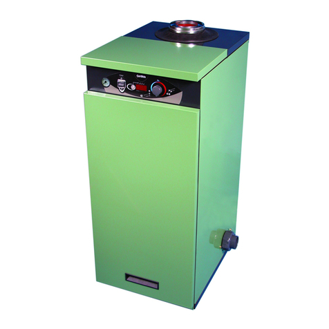
Certikin COH110 User guide

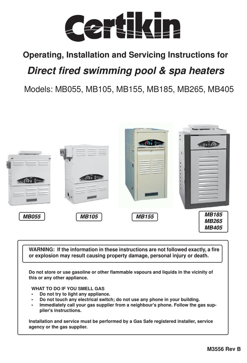
Operating, Installation and Servicing Instructions for
Indirect oil red pool & spa heaters
M3491G
Models: COH110, COH180, COH220, COH280

COH Oil Pool Heater 1 GB, IE
HEALTH AND SAFETY
Information for the installer, user & service engineer
Certikin International takes every reasonable care to ensure that these products are designed and
constructed to meet current safety requirements, when properly used and installed. To full this
requirement products are comprehensively tested and examined before despatch.
When working on the appliance it is the Users/Engineers responsibility to ensure that any neces-
sary personal protective clothing or equipment is worn appropriate to parts that could be consid-
ered as being hazardous to health and safety. This appliance may contain some of the materials
below.
INSULATION & SEALS
Glass Rope, Mineral Wool, Insulation Pads, Ceramic Fibre, Fibre Glass Insulation: may be harmful
if inhaled and/or may be irritating to the skin, eyes, nose or throat. When handling avoid inhalation
and contact with the skin or eyes. Use (disposable) gloves, face masks and eye protection. After
handling wash hands and other exposed parts. When disposing, reduce dust with water spray,
ensure parts are securely wrapped.
KEROSENE & GAS OIL FUELS (MINERAL OILS)
1. Avoid as far as possible any skin contact with mineral oil or clothing contaminated with mineral oil.
2. Skin rashes (oil Acne). Seek immediate medical attention for any rash, wart or sore developing
on any part of the body, particularly the scrotum.
3. Never breath any mineral oil vapours. Do not operate the burner in the open (i.e. out of the heater)
as a misre will cause unburnt oil vapours.
4. Barrier cream containing lanolin such as Rosalex Antisolv, is highly recommended together with
a strict routine of personal cleansing.
5. Under no circumstances should mineral oils be taken internally.
OFTEC Code of Practice OCP/1: For the Safe Installation, Commissioning, Maintenance and
Fault Rectication of Oil Firing Equipment should be consulted.
Due to a policy of continual development the manufacturer reserves the right to alter or amend the
design of its products without prior notice.
WARNING: If the information in these instructions are not followed exactly, a re or
explosion may result causing property damage, personal injury or death.
Do not store or use gasoline or other ammable vapors and liquids in the vicinity of this or
any other appliance.
THIS APPLIANCE MUST BE INSTALLED:-
• By a competent person.
• In accordance with the rules in force.
• in accordance with these operating, installation and servicing instructions.
• In open air or in a room which is separated from living rooms and provided with ap-
propriate ventilation directly to the outside.
READ THESE INSTRUCTIONS BEFORE INSTALLING AND OPERATING THIS APPLIANCE

COH Oil Pool Heater 2 GB, IE
SECTION 1 - USER INSTRUCTIONS
1:1 Safety Notes
1:2 Air Supply
1:3 Connections
1:4 Installation & Commissioning
1:5 Quick Start
1:6 Summary of Controls
1:7 Re-pressurising
1:8 Running the Pool Pump
1:9 Switching o, temporarily
1:10 Switching o for the winter
1:11 Oil delivery
1:12 Maintenance
1:13 Trouble shooting
1:14 Service
1:15 Water Quality
SECTION 2 - GENERAL INFORMATION
2:1 Introduction
2:2 Flue Options
2:3 Commissioning
2:4 Safety
SECTION 3 - TECHNICAL DATA
3:1 Liquid Fuels
3:2 Heater Technical Details
3:3 Burner Details
3:4 Electrics
3:5 Dimensions
3:6 Commissioning Data
SECTION 4 - INSTALLATION
4:1 Standards and Regulations
4:2 Heater Controls
4:3 Installation Wiring
4:4 If combined with heating
4:5 Siting & Positioning
4:6 The Hearth
4:7 Oil Storage
4:8 Oil Supply
4:9 Oil Burner
4:10 Sensor positions
4:11 Wiring Diagrams
SECTION 5 - FLUES
5:1 Conventional Flues
5:2 Air Supply
5:3 Balanced Flue Heaters
5:4 Balanced Flue Terminals
5:5 Terminal Guards
5:6 Positioning the Heater
SECTION 6 - BALANCED FLUE INSTAL-
LATION
6:1 Horizontal Balanced Flues
6:2 Vertical Balanced Flues
6:3 Outdoor Flue Kits
SECTION 7 - COMMISSIONING
7:1 General Information
7:2 Filling the Heater
7:3 Setting up the Controls
7:4 Pressure Switch
7:5 Responsibility
7:6 Reporting
7:7 Commissioning Check List
7:8 Commissioning Tests
SECTION 8 - MAINTENANCE
8:1 Maintenance
8:2 Air Shutter Adjustment
8:3 Bae Arrangement
SECTION 9 - SPARES & ACCESSORIES
9:1 Spare Parts
9:2 Accessories
9:3 Burner Parts
SECTION 10 - FAULT FINDING
10:1 General
10:2 Control Fault Diagnosis
10:3 Fault Finding Chart
CONTENTS

COH Oil Pool Heater 3 GB, IE
1: USER INSTRUCTIONS
1:1 Important Safety Notes
To obtain the best possible performance and trouble
free operation from your heater, it is important that
you read these instructions carefully. Your pool heater
has built-in safety features, which are detailed in the
relevant section of this manual.
Please note: It is essential in the interest of the heater
efficiency and reliable performance that once the
heater has been installed it is rst commissioned by an
OFTEC.* registered engineer. It is the responsibility of
the installer to ensure that the heater is commissioned.
If it is known or suspected that a fault exists on the
Heater, it MUST NOT be used until the fault has been
corrected by a competent engineer (see Section 1:13,
Trouble Shooting - Failure to Start)
It is essential that these instructions are strictly
followed for safe and economic operation. Failure to
observe these instructions may invalidate your right
to free breakdown cover during the guarantee period.
As this an oil burner appliance some parts will become
very hot and so care must be taken.
We recommend that you keep these instructions in a
place near your Heater for easy reference.
1:2 Air Supply to Heater - Conventional
Flue
Where your Heater is used on an open conventional
ue system, a permanent air supply is required for
combustion. Clearances provided for air entry at the
rear of the appliance and into the building in which it is
installed, must be kept free of obstruction. For further
explanation please refer to section 5:1 and 5:2.
1:3 Connections
Your Heater should be connected to an electrical sup-
ply complying with the Electrical Wiring Regulations
(BS7671): as well as an oil supply complying with
BS541; and an appropriate ue system.
ALWAYS SWITCH OFF THE ELECTRICAL SUP-
PLY before removing any of the covers for cleaning.
If any part of the Heater or its ue has been modied
without the manufacturers approval, the guarantee
will be invalidated.
1:4 Installation & Commissioning
After your Heater has been installed it MUST be
commissioned preferably by an OFTEC*. Registered
installer, or by one of our recommended service
engineers. Commissioning involves testing the Heater
to ensure that it is working correctly, and also set-
ting the Burner correctly to ensure the most ecient
operation and use of fuel. If the Heater has not been
commissioned, it may not be operating at the maxi-
mum eciency possible, and may also invalidate the
guarantee.
*The Oil Firing Technical Association Ltd 01473 626298
1:5 Quick Start
Check the Electricity and Oil supplies to the Heater
are on. If the Pool Pump is not controlled by the
Heater, turn it on. Turn on the Heater by turning the
Pool Temperature Control Knob clockwise to show
the required Pool temperature, the Heater will re.
If the Heater fails to light see Section 1:13, Trouble
Shooting - Failure to Start)
1:6 Summary of Controls (left to right)
Heater Pressure Gauge
Normal - The needle should be in the area indicated
as * * NORMAL * * , if low, re-pressurise, see Section
1:7
Pool Demand LED - GREEN
O - There is no Pool Heating Demand , pool heating
is o.
On -There is a Pool Heating Demand the pool is not
yet up to temperature.
Flashing - The Pool Heating Demand is Met , the
pool is up to temperature.

COH Oil Pool Heater 4 GB, IE
Pool / Spa Temperature Control Knob
16°C to 41°C (60°F to 106°F)
O - There is no Pool Heating Demand , pool heating
is o.
Pump - Runs Pool Pump only, if connected via
heater. ‘P’ is indicated on Pool Temperature Display.
- Pool + - Setting for pool temperatures. Requested
temperature is displayed when setting, actual Pool
Temperature is displayed after 3 seconds.
- Spa + - Setting for Spa Temperatures. Required
temperature is displayed when setting, actual Spa
Temperature displayed after 3 seconds.
(NOTE: The Heater is delivered set to display in
Fahrenheit. For a Centigrade display, see 7:3 Com-
missioning Section of Installation Instructions)
Pool Temperature Mechanical Stop
Stop – This can be used to obtain a repeatable set-
ting and to limit maximum pool temperature. To set,
loosen the screw, adjust as required and then re-
tighten.
Pool Temperature Display
Display - Normally shows the actual Pool Tempera-
ture, but also displays the Setting Temperature and
a Setting Dot lit whilst being adjusted. The display is
also used for commissioning and diagnostic pur-
poses.
Heating Demand LED - GREEN
(Only in use when heating system connected)
O - There is no Heating Demand , heating is
switched o.
On - There is a Heating Demand, heating is on but
not yet up to temperature.
Flashing - The Heating Demand is met , heating is
up to temperature.
Heating Temperature Control Knob (60 - 80oC)
(Only used when heating system connected)
O - There is no Heating Demand, heating is
switched o.
Normal - Normal setting for heating, it can be ad-
justed lower if required.
(NOTE: Supplied set for Pool Priority. It will satisfy
the Pool Temperature before supplying full Heating.
To change the priority, see 7:3 Commissioning Sec-
tion of the Installation Instructions)
Filter LED - YELLOW
On - Pool lter blocked - Insucient pressure, pos-
sibly due to a blocked pool lter. The heater will not
run.
Flashing - Clean pool lter - The lter may require
back washing. The heater will run. Can be reset by
turning the pool temperature knob o and back on
again.
Lockout - Oil? LED - RED
On - Lockout - Oil? - This indicates that the burner
cannot re, the probable cause is lack of fuel oil.
Check the oil tank. After 3 minutes press the But-
ton on the front of the burner to reset. If the problem
persists consult your service engineer.
Heater Overheat LED - RED
On - Heater Overheat - This indicates that the
Heater has overheated and shut down. See Press to
Reset Button instructions below.
Press to Reset Button
Press Reset Button when heater has cooled down. If
the problem persists consult a service engineer.
Automatic Frost Protection
Will operate in any control mode (except completely
powered o). Activated if the heater temperature
falls below 3oC (37oF). The burner and internal pump
are turned on (pool pump is turned o) until the
heater temperature rises above 10oC, when normal
operation will resume.
1:7 Re-Pressurising
Connect a Mains Water supply then connect the free
end of the braided exible hose (the Filling Loop)
(see Fig.2:1b) to the incoming mains connector.
Open the Valve to the supply, then, slowly open the
Valve on the Side Panel until the Pressure Gauge
shows 1 Bar.
Close both valves then disconnect the Filling Loop.
1:8 Running the Pool Pump
If this option has been installed the Heater can run
the Pool Pump on its own. Turn the Pool Tempera-
ture Control Knob to ‘Pump’, just next to O.

COH Oil Pool Heater 5 GB, IE
Fig 2:1b
Oil Filter
& line
Cold water
Mains inlet
Safety Outlet
From Pool
COH180 & COH220
Burner Lockout
Reset
Stop cock
1:9 Switching the Heater Off -
temporarily
The heater may be stopped by turning the Pool
Temperature Control Knob and/or the Heating Tem-
perature Control Knob to OFF on Control Panel.
Alternatively, the Heater may be stopped by turning
o the mains switch controlling the Heater.
1:10 Switching off for the Winter
Turn both temperature control knobs to o. If the
built in frost protection is required, do not isolate the
heater from its electrical or oil supply.
If the heater is to be shut o for the Winter, it is
advisable to have it thoroughly serviced when rst
shut down. Thorough cleaning will minimise corro-
sion during the idle period. Remember, when the
heater is required, to ensure that the oil supply is
open before switching on.
1:11 Oil Delivery
Always ensure the tank is topped up at regular in-
tervals rather than wait till it is nearly empty. This
will avoid tank deposits and water being sucked in
to the burner.
Where possible, it is advisable to temporarily switch
the heater o, and to keep it o for one hour after the
delivery. This is to allow any sediment to settle and
not be drawn into the heater. Failure to do this could
result in a blockage of the oil burner nozzle.
Please ask your supplier, or the driver to notify you
before the oil is discharged.

COH Oil Pool Heater 6 GB, IE
1:14 Servicing
To ensure ecient and reliable operation of the
Heater it is essential that the oil burner is initially
commissioned by a qualied engineer, and that an
annual service is given thereafter by an OFTEC
trained and registered engineer.
1:15 Water Quality
Chemical imbalance can cause severe damage to
your Heater and associated equipment.
Maintain the water pH between 7.4 and 7.6 and
ensure that the free chlorine levels are within the
range recommended by the chemicals manufacturer
for your size of pool.
Check the lter regularly and keep the pool free of
debris such as leaves and grass cuttings.
1:12 Maintenance
For normal cleaning of the outside casing, simply wipe
with a dry cloth. To remove stubborn marks and stains,
wipe with a damp cloth and nish o with a dry cloth. DO
NOT use abrasive cleaning materials. A spray of WD40
or similar will also help to protect it.
The Heater must be serviced at regular intervals by a
qualied service engineer. Failure to have the Heater
serviced at the recommended intervals will invalidate
the guarantee.
If using Kerosine Class C2 fuel, the Heater should be
serviced at twelve monthly intervals.
If using Gas Oil Class D fuel, the Heater should be
serviced at six monthly intervals.
All air intakes must remain clear at all times and so it
is advisable to inspect and clean these areas regularly.
Please refer to 4:6 later in this Installation manual for
further explanation.
1:13 Trouble Shooting - Failure to Start
If the Burner fails to start, adopt the following procedure:-
1. Check that there is oil in the tank and that the supply
valve is open.
2. Check that the Pool pump is operating and that the
Filter lamp is not illuminated.
3. Check that the Heater Control Thermostat is set high
enough to be “ON” and that the Pool Demand lamp
is on.
4. Check whether the Heater overheat light on the
control fascia is glowing, if so it indicates an overheat
situation. Press the reset button once the tempera-
ture has dropped suciently.
5. Check whether the red Lockout indicator on the
Control Panel and Burner Control box are glowing.
This indicates that the Burner has attempted to start
but has not red successfully. Press the reset button
on the Control box, when released, the lights will go
out and the Burner will again attempt to start. If the
Burner does not run and again goes to lockout with
red indicators glowing:-
· Wait three minutes.
· Repeat the procedure by pressing the button.
· Failure to start on the second attempt indicates a fault
requiring attention.
· Switch o the mains supply and call your service
engineer.

COH Oil Pool Heater 7 GB, IE
2: GENERAL INFORMATION
2:1 INTRODUCTION
This Manual covers Operation, Installation, Commis-
sioning and Maintenance of the Oil Fired Pool Heat-
ers.
The Pool Heaters are :-
· Designed for heating pools and spas by utilising an
internal water to water heat exchanger.
· Incorporates its own sealed system
components; pressure vessel, lling loop, safety
valve, and pressure gauge.
· Can also be used for space heating.
· Supplied with a manual reset limit thermostat.
· Suitable for new installations and for replacing
existing Heaters.
· Include an internal thermostatic bypass to maxim-
ise the life of the heat exchanger.
All models are supplied as standard with a low level
horizontal ring Oil Burner suitable for connection to a
conventional ue.
Note: The nozzle on this appliance is only covered by
a 1 year guarantee.
2:2 FLUE OPTIONS
The Heaters are designed to operate with high e-
ciency compliant with Section L of the Building Regu-
lations, clean combustion, and low noise levels.
Choice of ue systems are as follows:
· For connection to a conventional ue.
· Low level balanced ue, left, right or rear.
· Outdoor.
· Vertical Balanced ue.
See Section 9:2 for parts/accessories detail.
The tested balanced ue terminal and connection
aords an adequate supply of air for combustion and
equalisation of pressure between exhaust and intake
as required for operation under unfavourable wind
conditions.
Balanced ues are supplied in a carton that includes
ALL parts for a balanced ue installation.
The horizontal terminals are designed to avoid the
possibility of staining outer walls through which they
pass.
2:3 COMMISSIONING
It is essential in the interest of Heater eciency and
reliable performance that once the Heater has been
installed it is rst commissioned by a qualied engi-
neer.
If an engineer is not known, The Manufacturer will be
pleased to provide details of an OFTEC*
approved commissioning and servicing engineer from
their list of approved engineers.
See Section 7 for Commissioning Procedure.
It is the responsibility of the Installer
to ensure that the Heater is
commissioned by an OFTEC*
Registered Commissioning Engineer.
*The Oil Firing Technical Association, Ipswich,
IP5 2QQ Tel: 01473 626 298.
2:4 SAFETY
Should you wish to remove or
dismantle any covers or parts of the
Heater for cleaning or maintenance
ALWAYS FIRST SWITCH OFF THE
ELECTRICITY SUPPLY.
1. On no account should any part of the Heater or its
Flue be modied.
2. The wiring of the control panel should be as the
wiring diagrams included in this Manual. Wiring
should not be tampered with, modied or changed
for any reason.
3. Only use The Manufacturer’s replacement parts.
Noncompliance with the above will invalidate the
Guarantee.

COH Oil Pool Heater 8 GB, IE
3: TECHNICAL DATA
3:1 LIQUID FUELS
The Pool Heaters will burn liquid fuels complying with
BS2869 Part 2 1988 Classes C2 and D as specied
in the Code of Practice for Oil Firing BS5410 Part 1.
Heating Oil (Kerosine), also known as 28 sec oil
This fuel is suitable for all models. Burners are sup-
plied with the appropriate nozzle and pump pressure
as standard for this fuel.
They are set for the stated output. Details of all nozzle
sizes and pump pressure for all Heaters are shown on
the following pages.
Gas Oil (Red Diesel), also known as 35 sec oil
All models, can be adapted to burn Gas Oil. The
adaptation requires the alterations as detailed in the
data table 3:6.2.
The use of Class D (Gas Oil) for low level discharge
of combustion gases is NOT permitted under any
circumstances.
(Ref: OFTEC Technical Book 1).
3:2 HEATER TECHNICAL DETAILS
Maximum Heater working pressure 3 Bar (Class 2)
30.6m Water Head
Maximum hearth temperature less than 85°C
Maximum side panel temperature above room. less than 35°C
Minimum Conventional ue draught at Heater ue outlet 0.035”w.g. (8.75N/m²).
Maximum Conventional ue draught at Heater ue outlet 0.15”w.g. (37.5N/m²).
Water Resistance with 11°C temperature rise across the Heater 0.3m (1ft) wg
Recommended Filling Pressure 1 bar
Expansion Vessel 4 litres,
pre-charge pressure 1 bar
Fuses Heater 5 Amp
Control 250mA Anti-surge glass LRC
Pool Pump Output, maximum 3 Amp, 230V
3:3 BURNER DETAILS
Burner - Riello 40, 443T58, 459T55, 464T55. and RDB3 489T50
Manually adjustable air regulator. For further details of the burners, refer to the data sheets supplied in the
literature pack.
3:4 ELECTRICS
Electrical Supply 230v., 1 Ph., 50Hz.
All wiring to the supply and all system components external to Heater must comply with the latest edition of IEE
Wiring Regulations. This appliance must be eectively earthed and connection to the supply must be through
a double pole isolating switch.
Note: Pool Heaters with Outdoor Flue Kits.
IMPORTANT: THE OIL POOL HEATER IS SUPPLIED WITH A 13 AMP PLUG, THIS SHOULD NOT BE
USED OUTDOORS. ENSURE POWER SUPPLY IS IN ACCORDANCE WITH I.E.T. REGULATIONS AND
ANY LOCAL REGULATIONS WHICH APPLY.

COH Oil Pool Heater 9 GB, IE
3:5 DIMENSIONS
Height Depth Widths Service Clearances
Model A B C D Flue F G H Internal Pool Water Weight
mm mm mm mm Dia. mm mm mm Pump Connection Content Empty kg
* Speed mm litres
110 860 700 470 127 100 750 500 500 1 38 30 130
180 1000 725 510 169 125 750 500 500 2 38 38 190
220 1000 725 510 169 125 750 500 500 3 38 38 190
280 1100 870 590 191 150 750 500 500 *3/**N/A 38 59 310
*WILO standard eciency (with speed adjuster) ** WILO High eciency (xed speed)
3:6 COMMISSIONING DATA
3:6.1 Class C2 Heating Oil (Kerosine), also known as 28 sec oil
Fig 3:5a
B
D
F
GCH
A
Flue
Centre Line
Model Output Burner Pump Air Firing CO² % Smoke Flue Gas
Nozzle Pressure Shutter Rate l/h +/- 0.5%
US-GPH (kg/h) Approx
kW Btu/h Type Head x Angle Bar psi
TempºC
x 1000 Setting
Gross
110 26.4 90 443T58 Fixed 0.85 (3.31)x60W 7.2 105 2.9 2.32 11.5 0 - 1 200
180 44.0 150 459T55 0 1.35 (5.17)x60W 8.3 120 2.6 4.04 11.5 0 - 1 220
220 51.0 175 468T55 2 1.75 (6.55)x60W 6.9 100 4.5 5.00 11.5 0 -1 240
280 70.0 239 490T51 2 2.25 (8.35)x60W 7.6 110 8.5 6.53 11.5 0 -1 250

COH Oil Pool Heater 10 GB, IE
3:6.2 Class D Gas Oil (Red Diesel), also known as 35 sec oil
NOTE: Low Level discharge is NOT allowed
Gas Oil Conversion Components
4: INSTALLATION
4:1 STANDARDS & REGULATIONS
The installation of the Heater must comply with
latest edition of :-
BS 5410-1: Code of practice for oil ring installations
up to 45kW output capacity.
BS 5410-2: Code of practice for oil ring installations
over 45kW output capacity.
BS 7671: Requirements for electrical installations.
IET Wiring Regulations.
BS EN 12828: Heating systems in buildings. Design
for water-based heating systems.
BS EN 12831: Heating systems in buildings: Method
for calculation for the design heat load.
BS EN 14336: Heating systems in buildings. Instal-
lation and commissioning of water based heating
systems.
BS EN 1859 Metal chimneys. Test methods.
BS 7593: Code of practice for treatment of water in
hot water central heating systems.
BUILDING REGULATIONS.
Part J & G England and Wales
Part F Section lll Scotland
Part L Northern Ireland
The Control of Pollution (Oil) Regulations
Oil Heaters should be installed in accordance with
good practice as recommended by the OFTEC tech-
nical books 1 -7.
4:2 HEATER CONTROL
This Heater uses a control specically designed for it
and it has the following features:
• Accurate digital pool thermostat, 16°C to 41°C
(60°F to 106°F)
• Digital heater thermostat. Fixed for Pool, 84°C,
variable for Heating 60 - 82°C.
• Automatic frost protection
• Return thermostat operating an internal mechan-
ical bypass for condensation reduction.
• Mechanical overheat protection devices.
• Burner control with lockout.
• Internal Pump control with over-run.
• Pool pump control with over-run and out-of-sea-
son exercise. (Requires external contactor)
• Engineer selectable temperature display
(°C or °F).
• LED indicators for pool, heating, lockout, over-
heat, and service.
• Engineer indicators of all switched outputs for
simple diagnosis.
• Priority selection of Pool or Heating. Engineer
selectable.
• Memory of: Filter, Overheat and Lockout occur-
rences.
• Sensor failure detection and indication.
• Control self checking with fault indication.
For more detail see the Commissioning (7:1) an
Fault Finding (10:1) sections.
Model Nozzle Pre-Heater Conversion Kit Bottom Bae
110 SPCOH2/009 SPCOH2/008 Not required As Supplied
180 SPCOH2 SPCOH001 Not required As Supplied
220 SPCOH26 Not required Not required As Supplied
280 Not Available
Model Output Burner Nozzle Pump Air Firing CO² % Smoke Flue Gas
US-GPH (kg/h) Pressure Shutter Rate l/h +/-0.5%
kW Btu/h Type Head x Angle Bar psi Approx
x 1000 Setting TempºC
110 26.4 90 443T58 Fixed 0.75 (2.94)x60W 7.2 105 3.0 2.88 11.5 0 - 1 200
180 44.0 150 459T55 4 1.10 (4.24)x60W 9.3 135 4.0 4.84 11.5 0 - 1 220
220 51.0 175 464T55 2 1.25 (4.71)x60W 10.3 150 3.5 5.82 11.5 0 - 1 240
280 Not Available

COH Oil Pool Heater 11 GB, IE
4:3 INSTALLATION WIRING
The designs below are in order of preference, the CCP02 being the easiest, quickest and most comprehensive
solution.
Certikin Mk2 Oil Pool Heater
T.S
T.S
T.S
DESIGN
#
NOTES
Takes full advantage of all the features of the Certikin
Oil Pool Heater.
Pool Pump control providing overrun and Frost Protection action.
Provides the fastest installation
Optional connections for Lights and Space Heating all provided.
1
2
3
4
Takes full advantage of all the features of the Certikin
Oil Pool Heater.
Considerable installation time.
Pool Pump control providing overrun and Frost Protection action.
Optional Space Heating only available with more wiring.
Limited application of Certikin Oil Pool Heater.
Moderate installation time.
No Pool Pump control, Overrun or Frost Protection action.
Non-preferred application of Certikin Oil Pool Heater.
Moderate installation time.
No Pool Pump control, overrun or Frost Protection action.
Optional Lighting only available with more wiring.
Optional Space Heating only available with more wiring.
Optional Lighting only available with more wiring.
Utilising the CCP02 "Quick Fit" Oil Pool Heater Control
Optional Space Heating only available with more wiring.
Optional Lighting only available with more wiring.
T.S = Time switch
T.S = Time switch
T.S = Time switch
HTR = Oil Heater
HTR = Oil Heater
HTR = Oil Heater
CCP02
IMPORTANT: Remove link, Live to Pool Demand, in Heater
OR, Certikin Condensing 100 Pool Heater
OR, Certikin Condensing 100 Plus, Pool Heater
Lights
Up to 6A
Up to 16A
Pool Pump
LNE
Trip
> HTR
Permanent Live
> HTR
Pool Demand
< HTR
Pool Pump
Pool Pump
RELAY
Rated to
suit pump
N
N
More than 3A
Up to 3A
Trip
> HTR
Permanent Live
> HTR
Pool Demand
N
Pool Pump
Trip
> HTR
Permanent Live
> HTR
Pool Demand
N
Pool Pump
L
L
L

COH Oil Pool Heater 12 GB, IE
4:5 SITING & POSITIONING
Consideration must be given to the following points.
1. Noise may be accentuated by the installation in
small rooms or recesses with hard or hollow stud
wall surfaces. Due consideration to the siting of
heaters should be given.
2. Caution should be taken when siting this heater
near a coastal region, as this heater is particular-
ly vulnerable to corrosion from salty air. Speak to
Certikin for advice before installing near a coast.
3. Some individuals may be particularly sensitive to
even low noise levels and this should be dis-
cussed before installation.
4. The type of chimney, position relative to the
heater and whether a draught stabiliser is to be
tted may aect sound level in the room.
5. All models are serviced from the front and top.
A space of 500mm (18”) in front and above the
heater should be available.
6. Any kitchen work top above the heater must be
removable for service access.
4:6 THE HEARTH
All models have a hearth temperature of less than
85°C. The heater requires a level hearth to stand on
which should comply with local building regulations.
If the heater is to stand on a oor made of combustible
material then protection between the heater and the
oor should be provided by means of non-combustible
material.
Consideration should be given to the weight of the
heater and building regulations regarding oor load-
ing. Advice should be sought from your local building
control oce if there is any doubts regarding the oor
supporting the Heater.
The lled Heater weight can be found in 3:5.
4:7 OIL STORAGE
4:7.1 Oil Tank
Consideration to the access by fuel delivery lorries
should be given when positioning the oil tank.
Tank positioning should be in accordance with BS
5410 Part 1 and OFTEC Technical Book 3.
In the interest of most economical deliveries the oil
tank should be of 3,000 litres (600 gallons) capacity.
Heater
Pump Pump
Zone Valve
Non return valve
Pump
Non return valve
Second water 2 water
heat exchanger
with Aquastat or similar
Pool Plus Heating and Hot Water
Pool Plus Heating
Pool Plus Spa
3 Way Valve
NB: Add extra Expansion vessel to suit new system volume.
Expansion vessel Expansion vessel
Heater Expansion
Vessel
4 litres
Heater
Heater Expansion
Vessel
4 litres
Heater
Heater Expansion
Vessel
4 litres
Fig 4:3a
4:4 IF COMBINED WITH A HEATING
SYSTEM
The controls provide a water temperature control
for use with a heating system, the heating demand
knob.
It requires an electrical supply for heating demand to
be connected as shown in the wiring diagram and a
pipe circuit to be connected to the two rear tappings
of the heater in place of the air vent and drain.
It is essential that an additional expansion vessel is
added for the additional system volume.
depending upon the priority set (See commissioning,
7.1) the pool or heating will be brought up to tem-
perature rst.
The heating system should be installed in accordance
with current good practice as advised by HVCA.
Typical circuits are as follows.

COH Oil Pool Heater 13 GB, IE
It should be completed with the following:
1. Sludge cock - on steel tanks.
2. Outlet valve.
3. Contents Indicator.
4. Hinged ll and vent cover or a separate ll
connection and vent. The ll and vent should
be suitably capped to prevent ingress of water
or tted with return bends
4:7.2 Steel Tanks
Tanks should be mounted on suitable supports, if these
are of brick or blocks, a damp proof membrane should
be inserted between the tank and its supports.
Tanks should slope 20 mm per metre of length down-
wards from the oil Outlet to the sludge cock situated
at the opposite end.
4:7.3 Plastic Oil Tanks.
Tanks made from plastic are now available. These
should be UV stabilized for protection against sunlight,
and coloured green. Plastic tanks do not need to stand
on piers, but should be supported across the entire
base area, ideally on 50 mm thick garden slabs or a
concrete base. As there is only one tapped outlet they
are more suited to single pipe feed as gravity supply
or with a 3K Oil Loop De aerator where suction lift is
required. (Part No. BS 03060)
4:8 OIL SUPPLY
The oil connection points on the heater casing are
shown in the diagram Fig 7:2c in Section 7 of this
manual.
All joints in the oil lines must be oil tight and the oil
line should be ushed clean before connecting to the
burner.
4:8.1 Oil Filter
An Oil Filter is provided with the heater. Connections
are ¼ BSP Female, see Fig. 4:8b, 4:8c, 4:8d, 4:8e,
4:8f, 4:8g.
It is essential for reliable operation that the oil lter is
tted in the oil pipe supplying oil from the tank to the
burner. It is a condition of the guarantee that the lter
is tted correctly.
Please note: A lter must not be tted inside the heater
and all joints in the oil line must be oil tight. Soldered
joints are not permissible. Before connecting to the
heater, always ush the complete oil supply line and
ensure that the liquid fuel supply is completely clean
and free of any dirt or foreign matter.
4:8.2 Fire Check Valve (Not Supplied)
A 90°C re valve must be tted in the suction line see
BS 5410: Part 1.
The valve must be tted external to the heater, prefer-
ably at point where the oil pipe enters the building. The
sensor should be located above the Burner in the clip
provided, see Figs. 4:8a, 4:8b, 4:8d & 4:8f.
The entry point for the Fire Valve Sensor is shown on
Fig. 4:8a & Fig 7:2c.
To ensure the casing seal is maintained, always pass
the Sensor through the blind grommet (supplied), it will
be necessary to cut across the diaphragm.
4:8.3 Single Pipe System Fig. 4:8b
If the bottom of the oil tank is above the burner, install
a 10mm copper supply pipe to the burner incorporating
the correct Filter, shut o valve and re check valve.
Ensure that the burner oil pump is correctly set for
‘Single Pipe’ operation. (See section 4:8.2)
4:8.4 Two Pipe System Fig. 4:8d
When the bottom of the oil tank is below the level of
the oil pump on the burner it is necessary to install an
additional 10 mm return pipe.
The oil lter, shut o valve, spring loaded non-return
valve and re check valve are always in the suction
line supplying oil from the tank to the burner.
The non-return valve must be tted to allow the ow
in the correct direction and prevent drain back to the
Tank, see Fig. 4:8e.
Ensure that valves are NOT tted in the return line.
The return line must be unobstructed at all times.
Ensure that the burner oil pump is correctly set for ‘Two
Pipe’ operation. (See section 4:8.1)
4:8.5 De aerator Oil Pipe System Fig. 4:8f
An alternative two pipe arrangement can be achieved
using a 3K oil loop de aerator which removes the air
from the oil feed on a single pipe lift. The burner pump
is piped to the de aerator, which should be positioned
close to the burner, but NOT inside the heater Case.
A Non-Return valve is not required in the return line.
The advantage of this system is gained where a two
pipe run from the oil supply tank is long or dicult to
achieve. 3K de aerators are available as an optional
extra from your merchant (Part No. BS 03060).

COH Oil Pool Heater 14 GB, IE
Fig 4:9b Riello bypass adjustment

COH Oil Pool Heater 15 GB, IE
4:7.6 Water Separator Oil Filter
A Water Separator For Gas Oil is recommended (part
No. BS03052).
4:7.7 Flexible Oil Pipes
A exible burner oil hose is supplied with the heater
which must be wholly contained within the appliance
case.
4:8 OIL BURNER
The Burner manufacturers’ Technical Leaet is sup-
plied with this manual and provides supplementary
information not included in this manual.
4:8.1 Burner Pump for Two Pipe System
For two pipe oil systems the Burner Oil Pump has to
be tted with the Bypass Screw supplied. Heaters
are despatched with the Bypass Screw in a labelled
envelope attached to the Burner. This socket screw
is inserted into the return port as shown in Fig. 4:9a.

COH Oil Pool Heater 16 GB, IE
ONLY USE SUPPLIED BYPASS SCREW FOR
ALLEN KEY (2.5mm). DO NOT USE SLOTTED
SCREW TYPE.
4:8.2 Burner Pump for Single Pipe System
The burners are supplied set for single pipe opera-
tion. On the Riello burner the return port is plugged
and the Bypass Screw is not tted. See Fig. 4:9a.
4:9 SENSOR POSITIONS
The Heater Control Temperature Sensor ts into the
right hand pocket on the top of the Heater Heat
Exchanger.
The Limit Stat 8mm Coiled Phial ts into the second
pocket on the left hand side on the top of the Heater
Heat Exchanger.
TABLE GIVING MAXIMUM PIPE LENGTH ‘L’ Meters
‘H’ meters
10mm OIL PIPE 0.5 1.0 1.5 2.0
100 100 90 70
Bypass screw
must be tted

COH Oil Pool Heater 17 GB, IE
TABLE GIVING MAXIMUM PIPE LENGTH L Meters
10mm PIPE ‘H’ meters 0.5 1.0 1.5 2.0 3.0
100 100 100 100 100
Bypass screw
must be tted

COH Oil Pool Heater 18 GB, IE
4:10 WIRING DIAGRAM
SCHEMATIC WIRING
Fig. 4:10a

COH Oil Pool Heater 19 GB, IE
5: FLUES
5:1 CONVENTIONAL FLUE (FLUE 4” 5”
OR 6”)
CONVENTIONAL FLUE INSTALLATION ONLY.
FOR BALANCED FLUE INSTALLATIONS REFER TO
SECTION 5:3
The Heater requires a minimum stable draught of 0.1
mbar.
If the chimney exceeds 6m (20 feet) in length, it may
produce a draught exceeding 0.37 mbar and a draught
stabiliser should be tted.
The chimney should comply with the latest edition of the
Building Regulations and BS5410: Part 1.
Factory built chimneys must comply with the Building
Regulations and BS 4543 Parts 1 and 3.
Compliance with the Building Regulations does not indi-
cate that the chimney is satisfactory in respect of draught
conditions, or is positioned so that ‘down draughts’ will
not occur.
Special pots and cowls which might restrict the ow of
gases must not be tted and should be removed.
A brick chimney must be tted with a suitable stainless
steel liner. Insulation between the liner and an exposed
chimney may be necessary to avoid condensation.
A exible liner should be the same diameter as the Flue
Otake size of the Heater - 4”(100 mm), 5” (125 mm)
or 6” (150mm).
The Flue pipe, connecting the Heater to the chimney
should be the same diameter as the Heater Flue Otake
and should not be more than 1.8m ( 6’-0”) long. Flue
Pipes when tted should satisfy or be deemed to satisfy
the Building Regulations.
Flue pipe bends - 90º bends should be avoided use 135°
bends. Bends with soot doors should be used where
necessary.
5:2 AIR SUPPLY
CONVENTIONAL FLUE INSTALLATION ONLY IM-
PORTANT
A permanent adequate supply of air is required for com-
bustion and correct operation of a draught stabiliser, if
tted.
This air enters the Heater at the rear. It must never be
blocked o. At least 25 mm clearance is required at the
rear for all models.
When the Heater is situated in a conned space or cham-
ber a permanent adequate supply of air is required for
ventilation to prevent over heating.
5:2.1 Opening Sizes
The clear opening required for combustion only should
be based on a requirement of 550 mm²/kW, (or 1in² per
4000 Btu/h).
When a draught stabilizer is tted to the ue pipe or
chimney in the room in which the Heater is situated the
clear air intake should be 1100 mm²/ kW, (or 2in² per
4000 Btu/h).
When the Heater is situated in a conned space with
Combustion or Ventilation air from outside Allow 550
mm²/kW, (or 1in² per 4000 Btu/h) at low level and in ad-
dition 550 mm²/kW. (or 1in² per 4000 Btu/h) at high level;
When Combustion and Ventilation air is taken from a
heated adjoining space the allowance should be 1100
mm²/kW, (or 2in² per 4000 Btu/h) at low level and in
addition 1100 mm²/kW, (or 2in² per 4000 Btu/h) at high
level. Ensure that the heated adjoining space itself has
an adequate supply of air.
When the Heater is installed in a basement or at low level
where air can enter only from high level, the incoming air
supply for Combustion and Ventilation should be ducted
to low level. A high level outlet should be provided for
ventilation.
If the Heater is installed in a room with an extractor fan
the combustion performance must not be aected when
the fan is running with all doors and windows closed.
5:3 BALANCED FLUE HEATERS
Balanced Rear Flue Kits are available as optional extras
for each model. All models can be ued, at low level, side
or rear, and vertically to 6 metres.
Balanced Flues permit considerable choice of siting of
the Heater. Heaters may be installed in situations where
no chimney exists, where the existing chimney is unsat-
isfactory or in outhouses.
Please note, because of pipe connections for the Pool
it may be necessary to choose a longer than Standard
ue length for Left Hand ues.
It is important that care is exercised in choosing a suitable
location for the Heater and Flues.
Other manuals for COH110
2
This manual suits for next models
3
Table of contents
Other Certikin Heater manuals
Popular Heater manuals by other brands

dreo
dreo DR-HSH011 user manual

Webasto
Webasto Thermo Top V Operation and maintenance instructions

L.B. White
L.B. White Premier 350DF 2.0 Owner's manual and instructions

Jaga
Jaga BRIZA 041 Mounting instructions

Supra
Supra Dalbeo WiControl 1022 Installation and operating instructions

Trotec
Trotec IDE 20 D operating manual