TABLE OF CONTENTS
1VETTER SMARTFORK® OVERVIEW 6
1.1 Range of application 6
1.2 Overview of applications 7
1.2.1 VETTER SmartFork® Camera, camera function 8
1.2.2 VETTER SmartFork® SideCam, camera function 8
1.2.3 VETTER SmartFork® PremiumCam, camera function 9
1.2.4 VETTER SmartFork® Laser, line laser target function 9
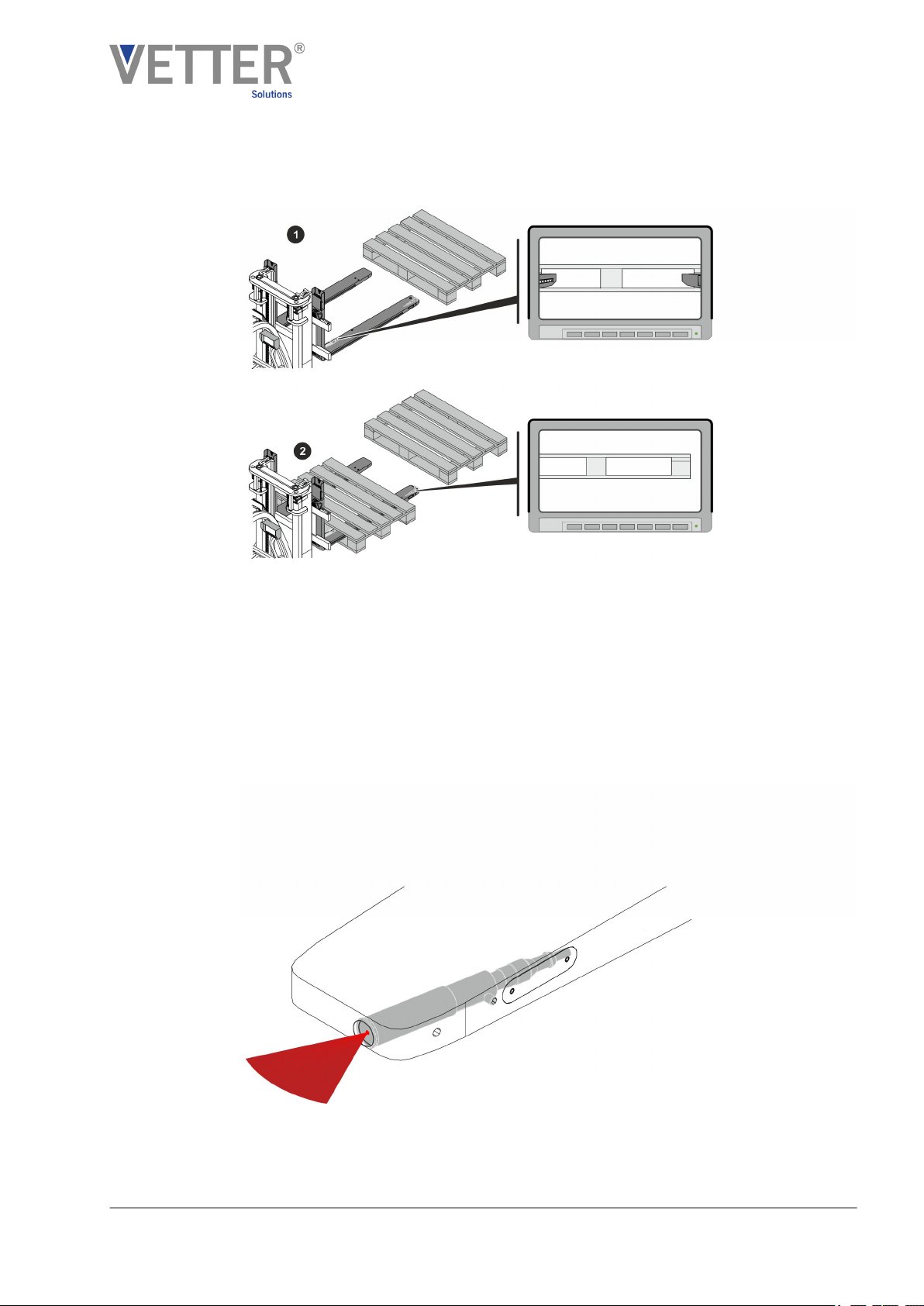
1.2.5 VETTER SmartFork® Secure, loading function 10
1.2.6 VETTER SmartFork® EasySecure, insertion depth function 11
1.2.7 VETTER SmartFork® Flash, warning function/insertion depth function 11
1.2.8 VETTER SmartFork® Level, tilt function 12
1.2.9 VETTER SmartFork® Distance, distance function 13
2 SAFETY 14
2.1 Symbols in this manual 14
2.2 Applicable documents 15
2.3 Intended use 16
2.4 Operator obligations 17
2.5 Dangers when handling the VETTER SmartFork®18
2.6 Safety markings 20
2.7 Personnel requirements 21
2.7.1 Qualifications 21
2.7.2 Unauthorised persons 23
2.7.3 Training 23
2.8 Personal protective gear 23
2.9 Protection of the environment and disposal 24
3STRUCTURE OF THE VETTER SMARTFORK®26
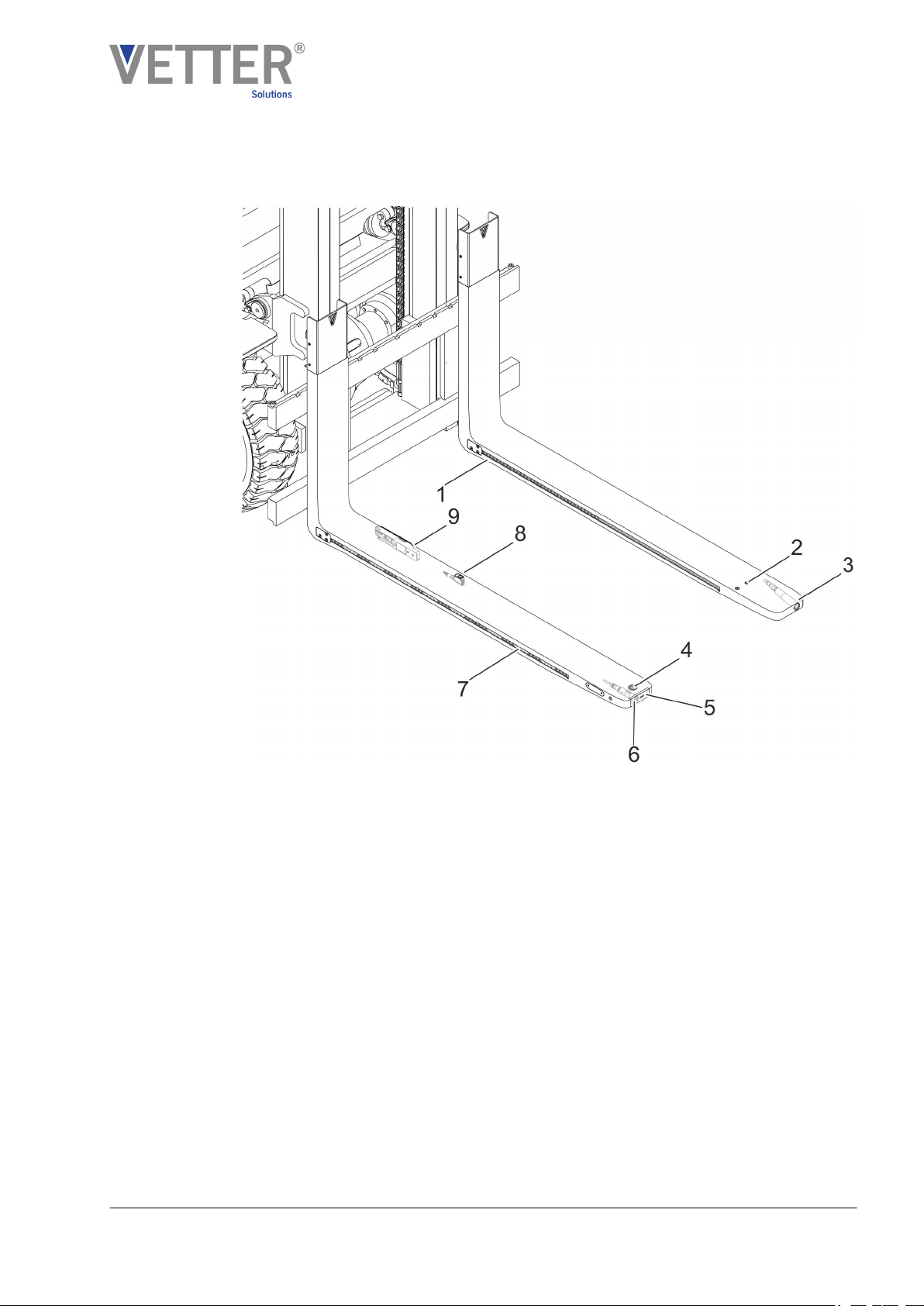
3.1 Structure of the basic fork 26
3.2 Suspension 27
3.3 Image and signal output devices 28
3.3.1 Camera monitor 28
3.3.2 VETTER EasySecure LED display 29
3.4 VETTER SmartFork® Flash control device 29
3.5 VETTER SmartFork® PremiumCam control device 29
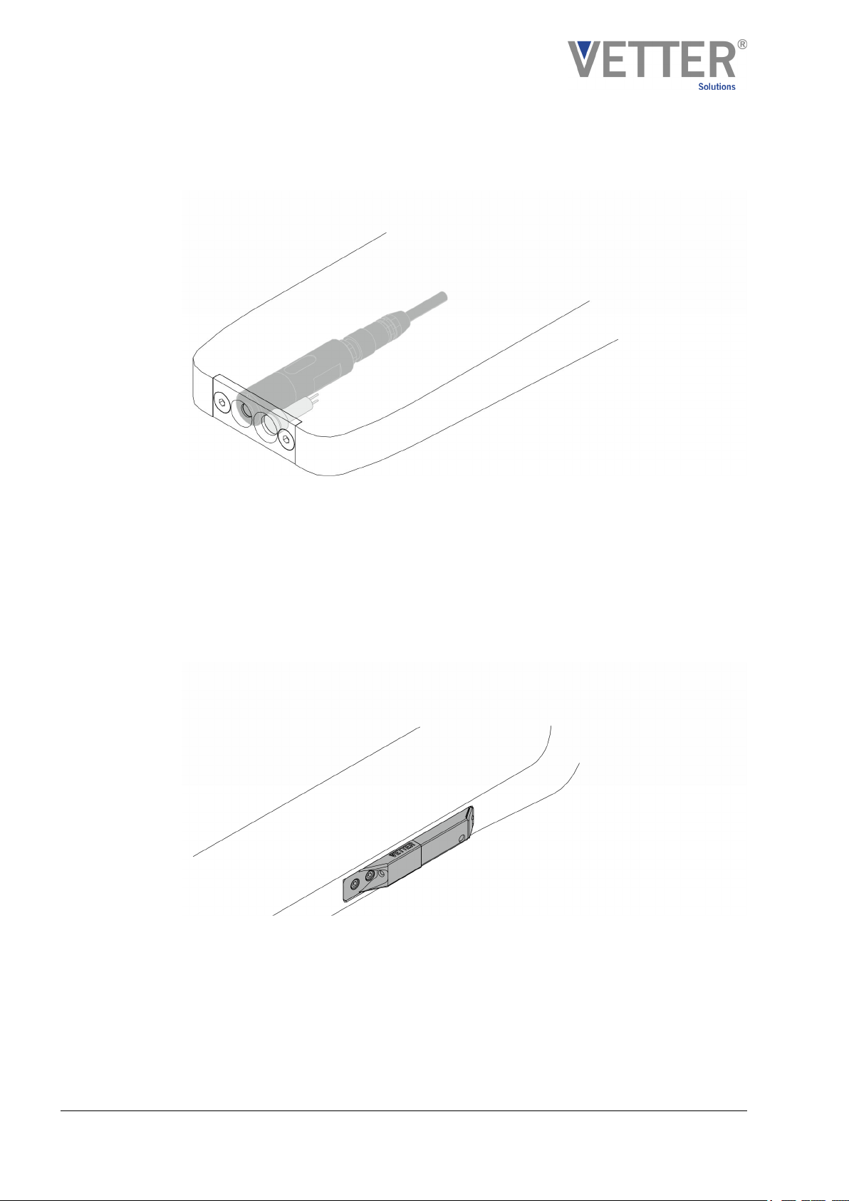
3.6 Cabling 30
3.7 Radio connection 31
4INITIAL ASSEMBLY OF THE VETTER SMARTFORK®32
4.1 Installing the VETTER SmartFork® on the fork carriage 32
4.2 Installing and connecting the monitor 33
4.3 Installing and connecting the EasySecure LED display 34
4.4 Establishing cable connections 35
4.5 Installing the radio transmitter 35
Table of contents
V1.08/2019SmartFork®- The intelligent SensorFork4