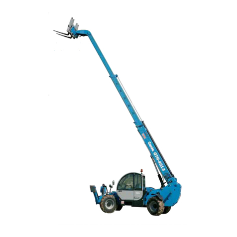
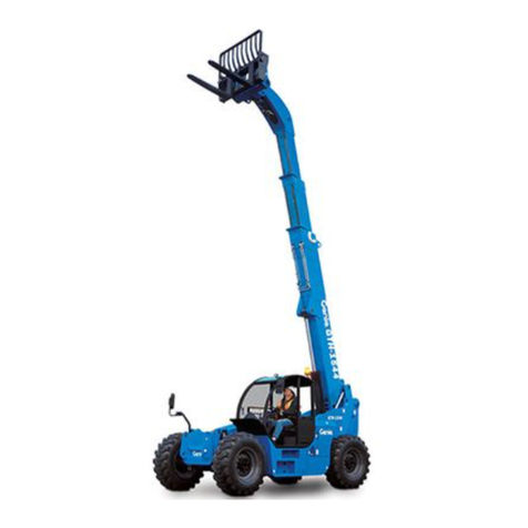
Terex GTH-1256 AF User manual

1.
Part No. 57.4400.9219
Rev C
September 2017
Serial Number Range
GTH-1256 AF From GTH12AFM-101
Service Manual

ii GTH-1256 AF Part No. 57.4400.9219
September 2017
Compliance
Machine Classification
Group B/Type 3 as defined by ISO 16368
Machine Design Life
Unrestricted with proper operation, inspection and
scheduled maintenance.
Important
Read, understand and obey the safety rules and
operating instructions in the Genie GTH 1256
AF Operator's Manual before attempting any
maintenance or repair procedure.
This manual provides detailed scheduled
maintenance information for the machine owner
and user. It also provides troubleshooting fault
codes and repair procedures for qualified service
professionals.
Basic mechanical, hydraulic and electrical
skills are required to perform most procedures.
However, several procedures require specialized
skills, tools, lifting equipment and a suitable
workshop. In these instances, we strongly
recommend that maintenance and repair be
performed at an authorized dealer service center.
Technical Publications
Genie has endeavored to deliver the highest
degree of accuracy possible. However, continuous
improvement of our products is a Genie policy.
Therefore, product specifications are subject to
change without notice.
Readers are encouraged to notify Genie of errors
and send in suggestions for improvement. All
communications will be carefully considered for
future printings of this and all other manuals.
Contact Us:
http://www.genielift.com
e-mail: [email protected]
Introduction
Copyright © 2017 by Terex Industries
57.4400.9219 Rev C September 2017
First Edition, First Printing
"Genie" and "GTH" are registered trademarks of
Terex South Dakota, Inc. in the USA and many other
countries.
Printed on recycled paper

September 2017
Part No. 57.4400.9219 GTH-1256 AF iii
Revision Date Section Procedure / Schematic Page /
Description
A 09/2016 Initial Release
B 11/2016 Section 6 Electrical Schematic updating
C 09/2017 Section 5,
6, 7 Addition of section 5, renumbering of section 6 and 7
REFERENCE EXAMPLES:
Perkins Engine_Section 2_Specifications.
A-5, B-8, C-1, D-5, E-2_Section 3_Maintenance
Procedure.
4-1, 4-2_Section 4_Repair Procedure.
Fault Codes_Section 6.
Section 7_Schematic Page #.
Electronic Version
Click on any procedure or page number
highlighted in blue to view the update.
Revision History

iv GTH-1256 AF Part No. 57.4400.9219
September 2017
REVISION HISTORY, CONTINUED
Revision Date Section Procedure / Schematic Page /
Description
REFERENCE EXAMPLES:
Perkins Engine_Section 2_Specifications.
A-5, B-8, C-1, D-5, E-2_Section 3_Maintenance
Procedure.
4-1, 4-2_Section 4_Repair Procedure.
Fault Codes_Section 6.
Section 7_Schematic Page #.
Electronic Version
Click on any procedure or page number
highlighted in blue to view the update.

September 2017
Part No. 57.4400.9219 GTH-1256 AF v
3930-01-647-7904
10,000 LBS
49,394 LBS
39,394 LBS
GSA-BPA-GS-07F-DA073
12 Mo
INTRODUCTION
Serial Number legend
GTH12AF
xxxxxM
5
1 Model
2 Facility code
3 Sequence number
4 Serial number (stamped on chassis)
5 Identification Plate

vi GTH-1256 AF Part No. 57.4400.9219
September 2017
This page intentionally left blank.

September 2017
Part No. 57.4400.9219 GTH-1256 AF vii
Section 1 • Safety Rules
Danger
Failure to obey the instructions and safety rules
in this manual and the appropriate Operator's
Manual on your machine will result in death or
serious injury.
Many of the hazards identified in the
Operator’s Manual are also safety hazards
when maintenance and repair procedures
are performed.
Do Not Perform Maintenance
Unless:
You are trained and qualified to perform
maintenance on this machine.
You read, understand and obey:
- manufacturer’s instructions and safety rules
- employer’s safety rules and worksite
regulations
- applicable governmental regulations
You have the appropriate tools, lifting
equipment and a suitable workshop.
Safety Rules

viii GTH-1256 AF Part No. 57.4400.9219
September 2017
Section 1 • Safety Rules
Personal Safety
Any person working on or around a machine must
be aware of all known safety hazards. Personal
safety and the continued safe operation of the
machine should be your top priority.
Read each procedure thoroughly. This
manual and the decals on the machine,
use signal words to identify the following:
Safety alert symbol—used to alert
personnel to potential personal
injury hazards. Obey all safety
messages that follow this symbol
to avoid possible injury or death.
Indicates an imminently
hazardous situation which, if not
avoided, will result in death or
serious injury.
Indicates a potentially hazardous
situation which, if not avoided,
could result in death or serious
injury.
Indicates a potentially hazardous
situation which, if not avoided,
may cause minor or moderate
injury.
Indicates a potentially hazardous
situation which, if not avoided,
may result in property damage.
Be sure to wear protective eye wear and
other protective clothing if the situation
warrants it.
Be aware of potential crushing hazards
such as moving parts, free swinging or
unsecured components when lifting or
placing loads. Always wear approved
steel-toed shoes.
DANGER
WARNING
CAUTION
NOTICE
Workplace Safety
Be sure to keep sparks, flames and
lighted tobacco away from flammable and
combustible materials like battery gases
and engine fuels. Always have an
approved fire extinguisher within easy
reach.
Be sure that all tools and working areas
are properly maintained and ready for
use. Keep work surfaces clean and free of
debris that could get into machine
components and cause damage.
Be sure any forklift, overhead crane or
other lifting or supporting device is fully
capable of supporting and stabilizing the
weight to be lifted. Use only chains or
straps that are in good condition and of
ample capacity.
Be sure that fasteners intended for one
time use (i.e., cotter pins and self-locking
nuts) are not reused. These components
may fail if they are used a second time.
Be sure to properly dispose of old oil or
other fluids. Use an approved container.
Please be environmentally safe.
Be sure that your workshop or work area
is properly ventilated and well lit.
SAFETY RULES
September 2017
Part No. 57.4400.9219 GTH-1256 AF ix
Introduction
Important Information .................................................................................. ii
Revision History...........................................................................................iii
Serial Number Legend................................................................................. v
Section 1 Safety Rules
General Safety Rules .................................................................................vii
Section 2 Specifications
Machine Specifications...........................................................................2 - 1
Performance Specifications....................................................................2 - 2
Hydraulic Specifications .........................................................................2 - 3
Hydraulic Components Specifications....................................................2 - 4
Function Manifold Specifications............................................................2 - 5
Air Conditioner Refrigerant Specifications..............................................2 - 5
Perkins 1104D-E44TA Engine ................................................................2 - 6
Dana Integral Gear Box..........................................................................2 - 7
Dana Axle ...............................................................................................2 - 7
Hydraulic Hose and Fitting Torque Specifications ..................................2 - 8
Torque Procedure ...................................................................................2 - 9
SAE and Metric Fasteners Torque Charts ............................................2 - 10
Section 3 Scheduled Maintenance Procedures
Introduction.............................................................................................3 - 1
Pre-delivery Preparation Report.............................................................3 - 3
Maintenance Inspection Report..............................................................3 - 4
Lubrication Chart ....................................................................................3 - 5
Table of Contents

x GTH-1256 AF Part No. 57.4400.9219
September 2017
TABLE OF CONTENTS
Section 3 Scheduled Maintenance Procedures, continued
Checklist A Procedures
A-1 Inspect the Manuals and Decals ..................................................3 - 6
A-2 Perform Pre-operation Inspection ................................................3 - 7
A-3 Perform Function Tests ................................................................3 - 7
A-4 Lubricate the Boom ......................................................................3 - 8
A-5 Perform Engine Maintenance.......................................................3 - 9
A-6 Safety Devices .............................................................................3 - 9
A-7 Inspect the Pre Filter ..................................................................3 - 10
A-8 Perform Axle Maintenance .........................................................3 - 10
A-9 Perform 30 Day Service ............................................................. 3 - 11
A-10 Perform Axle Maintenance ......................................................... 3 - 11
A-11 Perform Gear Box Maintenance.................................................3 - 12
A-12 Perform Axle Maintenance .........................................................3 - 12
A-13 Perform Engine Maintenance.....................................................3 - 13
A-14 Perform Engine Maintenance.....................................................3 - 13
Checklist B Procedures
B-1 Inspect the Electrical Wiring.......................................................3 - 14
B-2 Gear Box Oil Level ....................................................................3 - 15
B-3 Check the Exhaust System ........................................................3 - 15
B-4 Perform Axle Maintenance .........................................................3 - 16
B-5 Inspect the Tires, Wheels and Lug Nut Torque ..........................3 - 16
B-6 Perform Hydraulic Oil Analysis...................................................3 - 17
B-7 Check the Boom Wear Pads......................................................3 - 18
B-8 Perform Engine Maintenance.....................................................3 - 19

September 2017
Part No. 57.4400.9219 GTH-1256 AF xi
Section 3 Scheduled Maintenance Procedures, continued
Checklist C Procedures
C-1 Perform Engine Maintenance.....................................................3 - 20
C-2 Perform Engine Maintenance.....................................................3 - 20
C-3 Perform Engine Maintenance.....................................................3 - 21
C-4 Perform Axle Maintenance .........................................................3 - 21
C-5 Inspect and Lubricate the Sequencing Chains...........................3 - 22
Checklist D Procedures
D-1 Inspect the Forks........................................................................3 - 24
D-2 Tighten the Boom Chains...........................................................3 - 25
D-3 Replace the Hydraulic Tank Return Filter Element.....................3 - 26
D-4 Change Gear Box Oil ................................................................3 - 27
D-5 Perform Engine Maintenance.....................................................3 - 27
D-6 Perform Axle Maintenance .........................................................3 - 28
D-7 Replace Coolant Filter Element..................................................3 - 28
Checklist E Procedures
E-1 Test or Replace the Hydraulic Oil ...............................................3 - 29
E-2 Perform Engine Maintenance.....................................................3 - 30
E-3 Perform Engine Maintenance.....................................................3 - 30
E-4 Perform Engine Maintenance.....................................................3 - 31
E-5 Perform Engine Maintenance.....................................................3 - 31
TABLE OF CONTENTS

xii GTH-1256 AF Part No. 57.4400.9219
September 2017
Section 4 Repair Procedures
Introduction.............................................................................................4 - 1
Boom Components
1-1 Boom............................................................................................4 - 3
1-2 Boom Lift Cylinder...................................................................... 4 - 11
1-3 Boom Extend Cylinder................................................................4 - 12
1-4 Fork Level Slave Cylinder ..........................................................4 - 13
1-5 Fork Tilt Cylinder ........................................................................4 - 15
1-6 Boom Angle Proximity switch .....................................................4 - 16
Operator's compartment
2-1 Operator’s Compartment............................................................4 - 17
2-2 Machine Controls .......................................................................4 - 19
Fuel and Hydraulic Tanks
3-1 Fuel tank.....................................................................................4 - 22
3-2 Hydraulic tank.............................................................................4 - 23
Engines
4-1 Engine ........................................................................................4 - 24
4-2 Engine Fault Codes....................................................................4 - 24
Transmission
5-1 Gear Box ....................................................................................4 - 25
5-2 Axle ............................................................................................4 - 25
5-3 Rear Axle Lockout Cylinder........................................................4 - 26
Hydraulic pumps
6-1 Boom and Steering Function Pump ...........................................4 - 27
6-2 Auxiliary Gear Pump ..................................................................4 - 32
6-3 Hydrostatic Transmission Pump.................................................4 - 35
Manifold
7-1 Function Manifold.......................................................................4 - 39
7-2 Valve coils ..................................................................................4 - 42
TABLE OF CONTENTS

September 2017
Part No. 57.4400.9219 GTH-1256 AF xiii
Section 4 Repair Procedures, continued
Stabilizers
8-1 Stabilizers...................................................................................4 - 44
Forks
9-1 Forks ..........................................................................................4 - 45
Power Plant Heaters
10-1 Power Plant Heaters ..................................................................4 - 46
Webasto Heater
11-1 Webasto Heater .........................................................................4 - 50
AC Unit
12-1 AC Unit .......................................................................................4 - 51
Radiators
13-1 Radiators ....................................................................................4 - 52
Fuel System
14-1 Fuel System Prime .....................................................................4 - 54
Braking Circuit
15-1 Braking circuit.............................................................................4 - 55
Section 5 Long Term Storage Recommendation
Introduction.............................................................................................5 - 1
Section 6 Fault Codes
Introduction.............................................................................................6 - 1
Diagnostic Display..................................................................................6 - 2
Engine Fault Codes - Perkins 1104D-E44TA Engine .............................6 - 3
TABLE OF CONTENTS

xiv GTH-1256 AF Part No. 57.4400.9219
September 2017
Section 7 Schematics
Introduction.............................................................................................7 - 1
Electrical and Hydraulic Symbol Legends ..............................................7 - 2
Electrical Schematic ..............................................................................7 - 3
Hydraulic Schematic.............................................................................7 - 15

September 2017
Part No. 57.4400.9219 GTH-1256 AF 2-1
Section 2 • Specifications
Machine Specifications
Fluid capacities
Fuel tank 45 gallons
170 liters
Hydraulic tank 55 gallons
210 liters
Hydraulic system
(including tank)
82 gallons
310 liters
For operational specifications, refer to the
Operator's Manual.
Tires and wheels
Tire size 17.5 x 25
Tire ply rating 22
Weight, rough terrain tire
(air filled)
449.7 lbs
204 kg
Tire pressure
(models with air-filled tires)
94 psi
6.5 bar
Lug nut torque 546 ft-lbs
740 Nm
Lug pattern 10 x 13.189
Wheel diameter 53 in
135 cm
Wheel width 18 in
46.5 cm
Continuous improvement of our products
is a Genie policy. Product specifications are
subject to change without notice.
Specifications

2-2 GTH-1256 AF Part No. 57.4400.9219
September 2017
Section 2 • Specifications
Performance Specifications
Drive speed, maximum 15 mph
24 km/h
Draw bar pull 24000 lbs
10886 kg
Lift capacity, maximum 10000 lbs
4536 kg
Boom function speeds, maximum
Boom up 18 seconds
Boom down 21 seconds
Boom extend 25 seconds
Boom retract 33 seconds
Fork tilt up 6 seconds
Fork tilt down 5 seconds
Continuous improvement of our products
is a Genie policy. Product specifications are
subject to change without notice.
SPECIFICATIONS

September 2017
Part No. 57.4400.9219 GTH-1256 AF 2-3
Section 2 • Specifications
Hydraulic Specifications
Hydraulic Oil Specification
Hydraulic oil type
Viscosity grade
Viscosity index
Shell Tellus S4 VX 32
32
300
Cleanliness level,
minimum ISO 4406 21/19/16
Water content,
maximum 200 ppm
Optional fluids
Mineral based Shell Tellus S2 V 32
Shell Tellus S2 V 46
Chevron Aviation A
Eni Arnica 32
NOTICE
The hydraulic oil used in the
machine has been chosen
based on the temperature range
in which the machine will be
used. The optional oils indicated
herein can be used as well,
provided that temperatures do
not fall below the ones given in
the table below.
Optional fluid type Temperature range
Shell Tellus S2 V 32 -20°
Shell Tellus S2 V 46 -10°
Chevron Aviation A -20°
Eni Arnica 32 -20°
Continuous improvement of our products
is a Genie policy. Product specifications are
subject to change without notice.
SPECIFICATIONS

2-4 GTH-1256 AF Part No. 57.4400.9219
September 2017
Section 2 • Specifications
Hydraulic Components
Specifications
Boom and Steering Functions Pump
Type: variable displacement
piston pump
Displacement 0 to 3.7 cu in
0 to 60 cc
Flow rate @ 2200 rpm 35 gpm
132 l/min
Pump pressure, maximum
(measured at test port TP1)
4060 psi
280 bar
Pressure compensator
(measured at test port TP1)
4060 psi
280 bar
Stand-by pressure
(measured at test port TP5)
320 psi
22 bar
Auxiliary Gear Pump
Type: fixed displacement
gear pump
Displacement 1.53 cu in
25 cc
Flow rate @ 2200 rpm 15 gpm
56 l/min
Pump pressure, maximum
(measured at test port TP2)
2610 psi
180 bar
Relief valve pressure, maximum
(measured at test port TP2)
2610 psi
180 bar
Hydrostatic Transmission Pump
Type: variable displacement
piston pump
Displacement 0 to 5.5 cu in
0 to 90 cc
Flow rate @ 2200 rpm 52 gpm
198 L/min
Pump pressure, maximum
(measured at test port TP4)
6450 psi
445 bar
Relief valve pressure,
maximum
(measured at test port TP4)
6890 psi
475 bar
Pump charge relief valve
pressure, maximum
(measured at test port TP3)
406 psi
28 bar
Hydrostatic Transmission Motor
Type: variable displacement
piston motor
Displacement 0 to 7 cu in
0 to 115 cc
Flow rate @ 2200 rpm 52 gpm
198 l/min
Motor pressure, maximum
(measured at test port TP4)
6450 psi
445 bar
Relief valve pressure,
maximum
(measured at test port TP4)
6890 psi
475 bar
Continuous improvement of our products
is a Genie policy. Product specifications are
subject to change without notice.
SPECIFICATIONS

September 2017
Part No. 57.4400.9219 GTH-1256 AF 2-5
Section 2 • Specifications
Function Manifold
Specifications
Function Manifold
System relief valve pressure, maximum
(measured at test port TP1)
4060 psi
280 bar
Fork tilt relief valve pressure, maximum 4350 psi
300 bar
Steering Unit
Steer relief valve pressure, maximum 2610 psi
180 bar
Steer anti-shock valve pressure setting 3190 psi
220 bar
Air Conditioner Refrigerant
Specifications
System Full Charge
R134a 2 lbs 3 oz
Continuous improvement of our products
is a Genie policy. Product specifications are
subject to change without notice.
SPECIFICATIONS

2-6 GTH-1256 AF Part No. 57.4400.9219
September 2017
Section 2 • Specifications
Perkins 1104D-E44TA Engine
Displacement 268.5 cu in
4.4 liters
Number of cylinders 4
Bore and stroke 4.13 x 5 inches
105 x 127 mm
Horsepower 106 kW
142 hp
Peak Torque 558 Nm
Firing order 1 - 3 - 4 - 2
Compression ratio 16.2:1
Combustion Direct Injection
Governor Electronic
Low idle
Frequency
900 rpm
High idle
Frequency
2200 rpm
Lubrication system
Oil pressure (hot @ 2300 rpm)
Minimum pressure
300 kPa
43 psi
Oil capacity
(including filter)
7÷8,5 litres
7.4÷9 quarts
Oil viscosity requirements
Units ship with Shell Rimula R4 L 15W-40 API CJ4
low ash oil.
Extreme operating temperatures may require the use
of alternative engine oils. For oil requirements, refer
to the Engine Operation and Maintenance Manual on
your machine.
SPECIFICATIONS
Fuel requirements
For fuel requirements, refer to the engine Operation
Manual on your machine.
Engine coolant
Total Capacity 36 litres
Type VANGUARD ICE GUARD
–40 SPECIAL
45% water
55% antifreeze
(ASTM D3306,
ASTM D1384)
Alternator
Output 12 V, 120 Amp
Starter Motor
Relay max 68 A
Relay continuous 20 A
Glow Plugs
Initial load (0-4 sec) 82 A
Continuous load (>4 sec) 64 A
Battery
Type 12V DC
Group 4D
Quantity 1
Cold cranking ampere @
0°F
1110 A
Reserve capacity @ 25A
rate
200 minutes
Continuous improvement of our products
is a Genie policy. Product specifications are
subject to change without notic)e.
Table of contents
Other Terex Forklift manuals

Terex
Terex Genie GTH-1256 User manual

Terex
Terex GTH1516M-340 User manual

Terex
Terex Genie GTH-636 User manual

Terex
Terex Genie GTH10E-16000 User manual

Terex
Terex GTH1016E-11281 User manual

Terex
Terex GTH08E-13522 User manual

Terex
Terex Genie GTH1048 User manual

Terex
Terex Telelift 3713 SX User manual

Terex
Terex Genie GTH1513B-2 User manual

Terex
Terex GTH8E-11500 User manual