CESVA LF010 User manual

LF010
Sound level limiter
1/3 Octave band spectrum analyser and recorder
USER’S MANUAL
M_LF010_v0010_20230606_EN


1
founded in 1969 in Barcelona, has always engaged in the
manufacturing of sound equipment and instruments with in-house R&D&I and
patents.
We are members of national and international committees for the creation and
review of regulations and standards.
has a flexible and efficient distribution network in more than 40
countries all over the world.
We provide our customers with an after-sales service that guarantees our
instruments have a long service life, as well as verification and calibration
services.
Our website is where you can find all the information you need to know about our
products, request free quotes with no commitment to purchase, download
software, get in touch with us or simply remain abreast of all the training activities
and exhibitions that we regularly take part in.
Taking care of and listening to our customers brings us closer to them and allows
us to provide them with a measuring solution that is totally adapted to their
needs.

2 Contents
1. What is in this manual? 4
2. General description of the device 5
2.1 LF010 Sound level limiter and 1/3 octave band spectrum
analyser and recorder 5
2.2 Main Features of the LF010 5
2.3 Device parts 8
3. LF010 web server 10
3.1 Access to the web server 10
3.2 Display data 10
3.3 Video output 12
3.4 Support 13
3.5 Sign out 13
4. Touchscreen 14
4.1 Navigation bar 14
4.2 Main menu 14
4.3 Information Screens 15
4.3.1 Emission 15
4.3.2 Reception 15
4.3.3 Attenuation 16
4.3.4 1/3 octave emission 17
4.3.5 1/3 octave reception 17
4.3.6 Secondary sensors 18
4.3.7 Indicator legends 18
4.4 Direct mode 19
4.5 LF010 Status 20
5. Accessories 23
5.1 Standard accessories 23
5.2 Optional accessories 23
6. Technical specifications 24
6.1 GENERAL CHARACTERISTICS 24
6.2 INPUTS AND OUTPUTS 24
6.2.1 Audio inputs and outputs 24
Contents

Contents 3
6.2.2 Main and secondary sensor input 25
6.2.3 Cable for connecting the sensor to the limiter 25
6.2.4 Fire alarm input 25
6.2.5 Output for the connection of the DL010 external display 26
6.2.6 Full HD video output for HDMI displays 26
6.2.7 Ethernet Communication 26
6.2.8 Wireless LAN communication (WIFI) 26
6.3 FRONT SCREEN 26
6.4 ATTENUATOR 26
6.5 EQUALISER 27
6.6 SENSOR 27
6.7 1/3 OCTAVE BAND FILTERS 27
6.8 STANDARDS 27
7. Maintenance and precautions 28
7.1 Recommendations for use 28
7.2 Safety precautions and warnings 28

4 Chapter 1 What is in this manual?
This manual provides you with the following information about the LF010 limiter:
Chapter 2 describes the main features of the device and its physical parts.
Chapter 3 explains how the Web server works when accessed by the “user”
profile.
Chapter 4 focuses on explaining the device’s touchscreen.
Chapter 5 lists all the device’s accessories.
Chapter 6 contains the LF010’s Technical Specifications.
And finally, Chapter 7 contains information about maintenance and precautions
to bear in mind.
What is in this manual?
1. What is in this manual?
1

Chapter 2 General description of the device 5
This chapter provides an overview of the LF010 limiter. It describes all the
possibilities offered by the LF010 and its main characteristics, as well as
identifying its different parts.
2.1 LF010 Sound level limiter and 1/3 octave band spectrum
analyser and recorder
The LF010 limiter continues the philosophy of offering the ideal
balance between noise control and maximum music quality while also respecting
the dynamics of the music and offering clear, distortion-free and uncut music.
Thanks to its power, the LF010 measures the existing sound level in the music
venue (emission) at up to four points (one main control sensor and up to 3
optional secondary ones) and the sound level transmitted to a neighbouring
house, opposite façade or a point outside (reception) thanks to the frequency
information on 1/3 octave sound insulation between 50 Hz and 5 kHz. It also
records the time evolution of these levels and spectra in its memory, as well as
any incidents and tampering detected.
The LF010 uses the measured levels to control the overall music level
(unequalized) so that the programmed emission and reception limits are not
exceeded in the three day/evening/night time zones. The LF010 performs this
control using different Attack and Release modes to adapt its performance to live
concerts with great dynamics as well as to dance music club sessions.
2.2 Main Features of the LF010
The LF010 is a high-performance sound level limiter with the following main
characteristics:
ACCURACY AND POWER:
•It continuously MEASURES AND RECORDS the sound EMISSION level in
the venue and the level of IMMISSION in the RECEIVING environment
(adjacent house, point outside or opposite façade) thanks to the programmed
1/3 octave band sound insulation (50 Hz to 5 kHz).
•It MEASURES AND RECORDS a wide range of ACOUSTIC FUNCTIONS:
LAeq, LCeq, Moving LAeq, Expected music level, 1/3 octave band sound
spectrum (50 Hz to 5 kHz).
General description of the device
2. General description of the device
2

6 Chapter 2 General description of the device
•When the sensors cannot be deployed at the desired measuring point, the
LF010 allows you to apply different OFFSETS to each sensor.
•The XP010 MAIN sensor and the XS010 SECONDARY sensors have a
CLASS 1 measuring accuracy according to IEC 61672-1. The 50 Hz to 5 kHz
1/3 octave band filters comply with IEC 61260 and the CTE (National Building
Code).
•It detects TAMPERING of the limiter, sensors and sound system: Emission
and reception limit exceedance, parallel sources, tampering of the limiter and
the sound system chain, and tampering, disconnection or change of the main
and secondary sensors. The LF010, the XP010 main sensor and the XS010
secondary sensors are fully sealable.
•It records sound levels and incidents on a BY MINUTE basis and can commit
two years of information to memory every 10 minutes. It also records all
actions performed in the limiter, keeping track of what has been done, when
and by whom.
•The LF010 also has a front COLOUR TOUCHSCREEN to display the
measured information and communication status.
Full HD 1080p VIDEO OUTPUT:
•The video output is compatible with HDMI DISPLAYS and allows the sound
engineer/DJ to view clear and user-friendly information in real time to keep the
sound levels under optimal control and below the limit. This new approach
gives control to the DJ so that the limiter does not have to abruptly attenuate
the sound level.
•It allows the activity owner to afford greater exposure to the EVENTS,
PARTIES and ADVERTISEMENTS of sponsoring brands or to showcase their
own articles and promotions.
ADAPTABLE LIMITATION AND CONTROL:
•It enables you to program different emission and reception LIMITS for the
three DAY/EVENING/NIGHT time zones.
•It has different control modes for emission and reception and
ATTACK/RELEASE that can be configured with different speeds
(slow/medium/fast).
•It includes a MUSIC GAP detection system that maintains attenuation
between song tracks, making it ideal for playlists or CDs with gaps between
tracks.
•It features the ENOS (Extraneous Noise Override System) system that allows
uncut playback or kills audience shouting or clapping: Live concerts, sports
broadcasts, etc.
•The LF010 limiter can completely MUTE the music if the limiter is not
connected to the mains, it can switch off the main sensor, apply periods of
silence at the end of the session (schedule control) or activate a voice-
operated alarm for evacuation and emergency applications.
EASY TO INSTALL:
•It is very easy to install, as it has a built-in responsive design web server that
allows you to install, program and download data from a laptop, tablet or

Chapter 2 General description of the device 7
smartphone (Windows, iOS, Linux, Android) via an Ethernet (RJ45) or WIFI
connection.
•It has its own communication systems (Ethernet and WIFI) to connect to the
Internet and to the LIDACO or GALILEO activity inspection platforms. A
simple optional access point (modem) is all you need for non-Internet-
connected activities. The limiter can also be programmed remotely through
the LIDACO platform.
•It also has a 1/3 octave band GRAPHIC EQUALISER (10 Hz to 20 kHz) to
equalize the room and achieve the highest possible sound quality.
•It guarantees MINIMUM NOISE for any type of source: Mixer, MP3 player,
laptop with multimedia playback programs, subscription services such as
Spotify or professional mixing software.
•It automatically adjusts the SOUND SYSTEM’S CAPACITY to the
programmed limit (DEN and emission/reception). This allows the DJ/sound
technician to work with the same mixer levels regardless of limit.
•It has a BIANNUAL CALENDAR for programming closing times for public
holidays, holidays and special public holidays (New Year’s Eve).
•It also features the FINAL TEST option to perform a short 3-minute test to
verify that the limiter is properly installed and also to check, in a quick and
straightforward fashion, connection to the Internet and to the LIDACO
platform.
UP TO THREE SECONDARY SENSORS:
•It has 1 main control sensor that can be complemented by up to 3 additional
secondary sensors; all PRE-CALIBRATED with no need for any adjustment.
The number of additional secondary sensors recommended is: 1 for L-shaped
rooms, 2 for U-shaped rooms or 3 for large rooms.
•It can detect the tampering of all the sensors, including the secondary ones,
and it monitors the SERIAL NUMBER of all of them, thus preventing
fraudulent use of different sensors.

8 Chapter 2 General description of the device
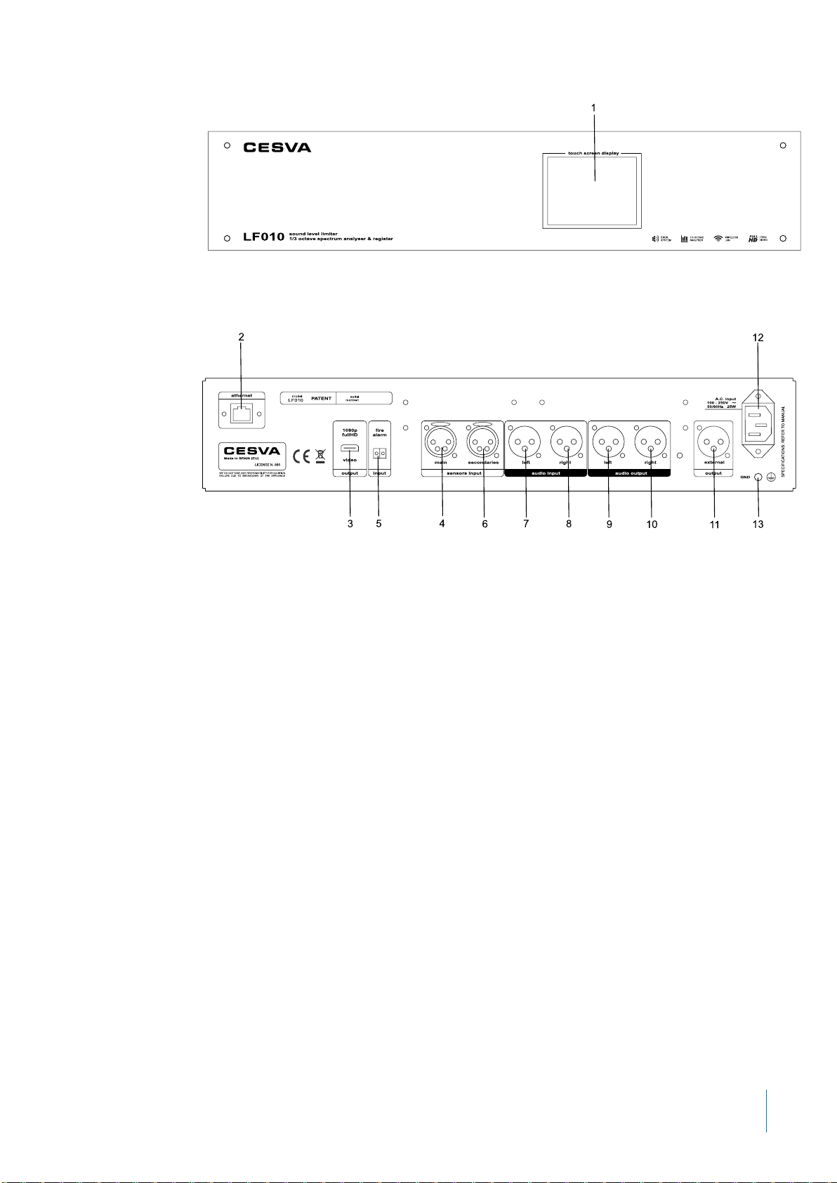
2.3 Device parts
The following figure describes the most important parts of the LF010:
1. Touchscreen·The LF010 has a front touch screen for viewing different
information about the limiter and for activating direct communication mode.
2. LAN connector for Ethernet connection ·
3. Full HD 1080p VIDEO OUTPUT ·This output is for displaying information from
the LF010 on displays with HDMI inputs.
4. Main sensor input ·
5. Fire alarm input ·Input for a control signal from a fire alarm.
6. Secondary sensor input ·More than one secondary sensor can be connected
using the XH010 hub.
7. Left channel balanced audio input (XLR) ·
8. Right channel balanced audio input (XLR) ·
9. Left channel balanced audio output (XLR) ·
10. Right channel balanced audio output (XLR) ·
11. External display output ·Output for connecting the DL010 external display
that indicates the sound pressure level in dBA in real time.
12. Power connector ·100-230V 50/60Hz.
13. Ground connection ·
Chapter 2 General description of the device 9
10 Chapter 3 LF010 Web server
Below, a description is given of the LF010’s web server when accessed by the
“user” profile.
Section 3.1 describes how to access the web server. When you access it, you
will see a main menu* with several detailed options between sections 3.2 and
3.5.
3.1 Access to the web server
You can access the web server with an external device that has a web browser:
a desktop computer or laptop, tablet, smartphone, etc.
Unless the installer of the limiter indicates otherwise, access to the web server
must be obtained by activating “Direct Mode” on the limiter’s touch screen, as
described in section 4.4.
On the web server homepage, choose the “user” option and enter the password
provided by the installer of the limiter. The default password is “admin”.
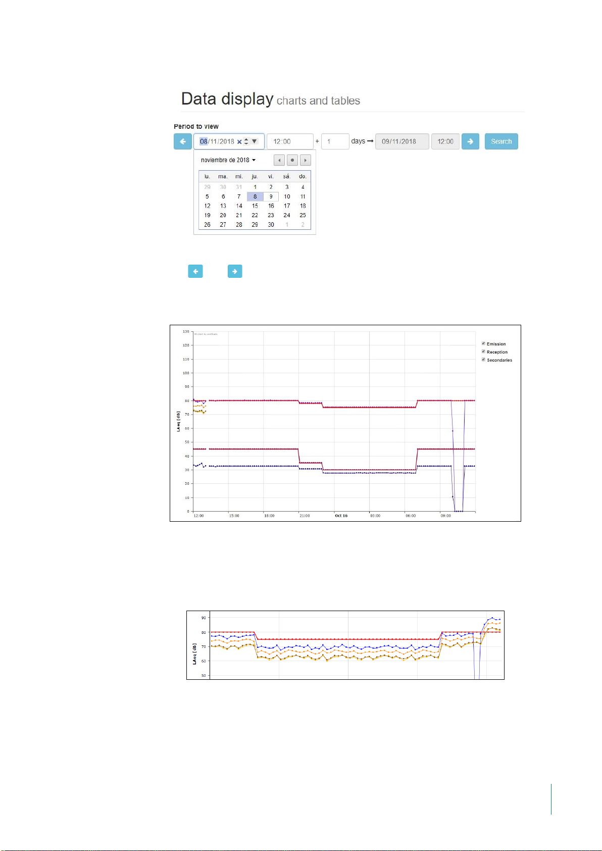
3.2 Display data
This option displays the limiter’s data as a chart and numerically for the day or
two days selected. The different levels measured by the limiter’s sensor or
sensors and the limits established are displayed.
At the top, you can select the period’s starting date and its duration (one or two
days) using the white boxes (shaded-in boxes cannot be modified). The data are
displayed from the time selected on the first day until the same time on the last
day of the period selected.
Pressing opens up a calendar where you can select the specific start date for
the period.
LF010 web server
3. LF010 web server
3
NOTE*: You will need to press the button on some devices and on smart
phones to view the main menu.
Chapter 3 LF010 Web server 11
Use the and arrows to go forward or back one period.
Pressing the “search” button displays the data for the selected period on a chart:
•The values measured by the main sensor, by the secondary sensors (if
there are any) and the existing emission limit are displayed in a chart in
the middle:
•The reception values and the existing reception limit are displayed at the
bottom:
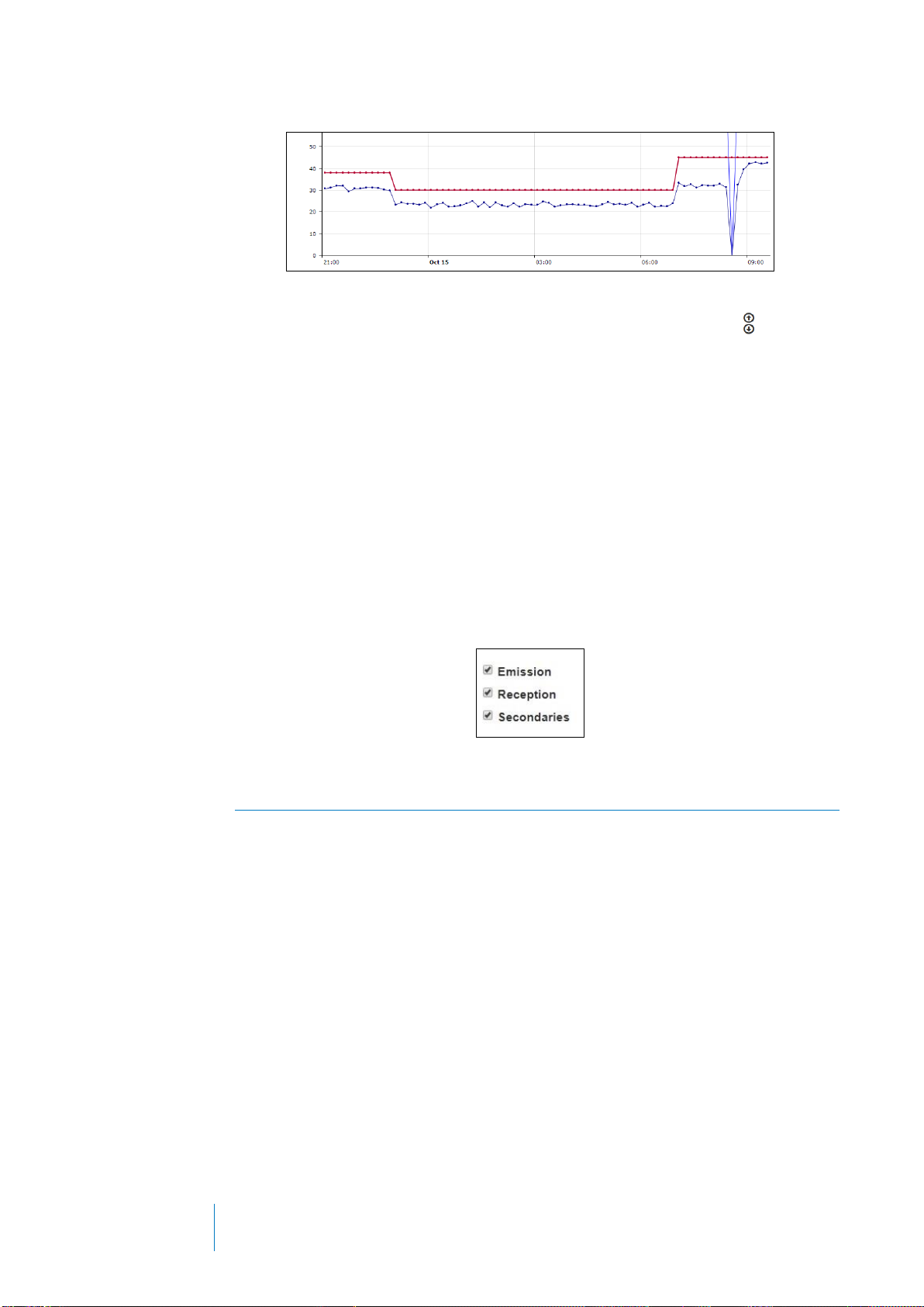
12 Chapter 3 LF010 Web server
The data are displayed in numerical format below the chart. Use the arrows for
fast access to the chart and the numerical part.
The numerical display of the limiter’s data is also separated into colours to
facilitate a visual analysis of the data. The period’s starting and end date, its
duration and whether or not we are within session time are displayed on the left
side of the table in grey. The emission data are represented in sky blue and
reception data in blue. If there are secondary sensors, the relevant information is
displayed in orange for the first secondary sensor, yellow for the second and
brown for the third.
Activate or deactivate the following boxes (located on the top right hand side of
the display) to select the date you wish to display:
3.3 Video output
This option configures the information to be displayed on an external HDMI
display connected to the 1080p full HD output [3]:
The LF010 allows you to choose from different options that are available in the
“Display type” section. The “Example” section shows a graphic example of the
selected option. The “Functions setting” section shows the different functions that
are available for display depending on the type of display selected.
There are options (DJ) designed to allow the sound engineer/DJ to view clear
and user-friendly information in real time to keep the sound levels under optimal
control and below the limit. This new approach gives control to the DJ so that the
limiter does not have to abruptly attenuate the sound level. There are also
options (Public) that allow the activity owner to load a banner to afford greater
exposure to events, parties, advertisements of sponsoring brands or to showcase
their own articles and promotions.
If you select a “display type” with banner, upload the .gif file to the “Banner”
section. For the banner to be displayed correctly, it must have the specified
dimensions (1920x300 for small banners, 1920x980 for large banners and

Chapter 3 LF010 Web server 13
1920x1080 for full ones). A .gif file containing different images may be uploaded,
in which case each image will be displayed for one minute as a slide-show.
Press “Save” to send all settings to the LF010 limiter.
3.4 Support
Select the “Support” option on the main menu to download this document in .pdf
format.
3.5 Sign out
Select the “Sign out” option to close the current session.
14 Chapter 4 Touchscreen
This chapter deals with the touchscreen located on the front of the LF010 which
displays the limiter’s different parameters and where direct communication mode
can be activated.
4.1 Navigation bar
A navigation bar with the following options is displayed at the bottom of the
LF010’s touchscreen:
→Arrows for navigating through the different information screens.
→Icon for accessing the main menu.
→The LF010 limiter’s time
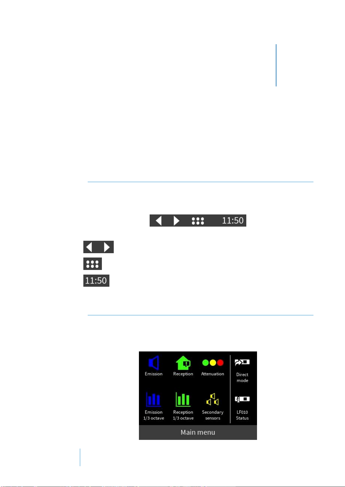
4.2 Main menu
The left side of the main screen contains 6 icons which when pressed provide
access to different information screens. On the right side there are another two
icons to activate direct communication mode and to consult the LF010 limiter’s
status.
Touchscreen
4. Touchscreen
4
Chapter 4 Touchscreen 15
4.3 Information Screens
The main menu contains the following 6 icons which, when pressed, display their
respective information screen:
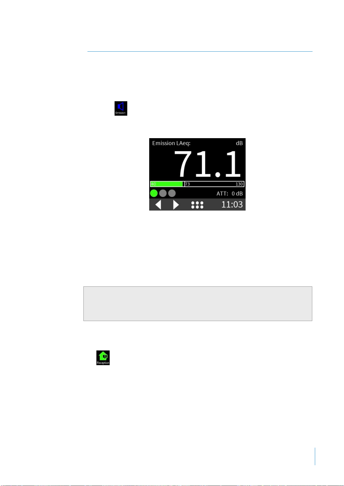
4.3.1 Emission
Press the icon to display the LAeq Emission(1) sound level in real time
measured by the main sensor.
The lower bar (which goes from 40 dBA to 130 dBA) represents the LAeq
Emission(1) level graphically. It is displayed in green if the emission limit value
(indicated on the bar) is not exceeded and in red if the emission limit is
exceeded.
There will be different indicators below the bar depending on the information to
be displayed. Section 4.3.7 provides further information about these indicators.
4.3.2 Reception
The icon is enabled if reception limits are configured in the LF010 limiter.
Otherwise this icon will be disabled.
If it is enabled, when pressed it displays the LAeq Reception(1) value in real time
calculated from the spectral measurement of the main sensor and taking the
frequency insulation entered into the LF010 limiter into account.
NOTE(1):LAeq Emission/Reception is the equivalent continuous sound level
with moving integration time of 5 seconds with frequency weighting A.

16 Chapter 4 Touchscreen
The lower bar (which goes from 0 dBA to 80 dBA) represents the LAeq
Reception(1) level. It is displayed in green if the reception limit value (indicated on
the bar) is not exceeded and in red if the reception limit is exceeded.
There will be different indicators below the bar depending on the information to
be displayed. Section 4.3.7 provides further information about these indicators.
4.3.3 Attenuation
Press the icon to access the following screen:
There will be different indicators at the top depending on the information to be
displayed. Section 4.3.7 provides further information about these indicators.
If playback is not muted (MUTE) on the limiter, information about the session is
displayed in the top right corner:
- The word “Session” means that there is an ongoing session and the time
remaining until it ends is displayed (in HH:mm format).
- The words “Session out” mean that there is no ongoing session.
- The word “Silence” means that we are in a silence period (the limiter will
not play a music signal back), and the time remaining until the end of this
period is displayed (in HH:mm format).
The graphic bar corresponding to the LAeq Emission(1) level is displayed in the
centre of the screen.
And the graphic bar corresponding to the LAeq Reception(1) level is displayed at
the bottom of the screen.
Chapter 4 Touchscreen 17
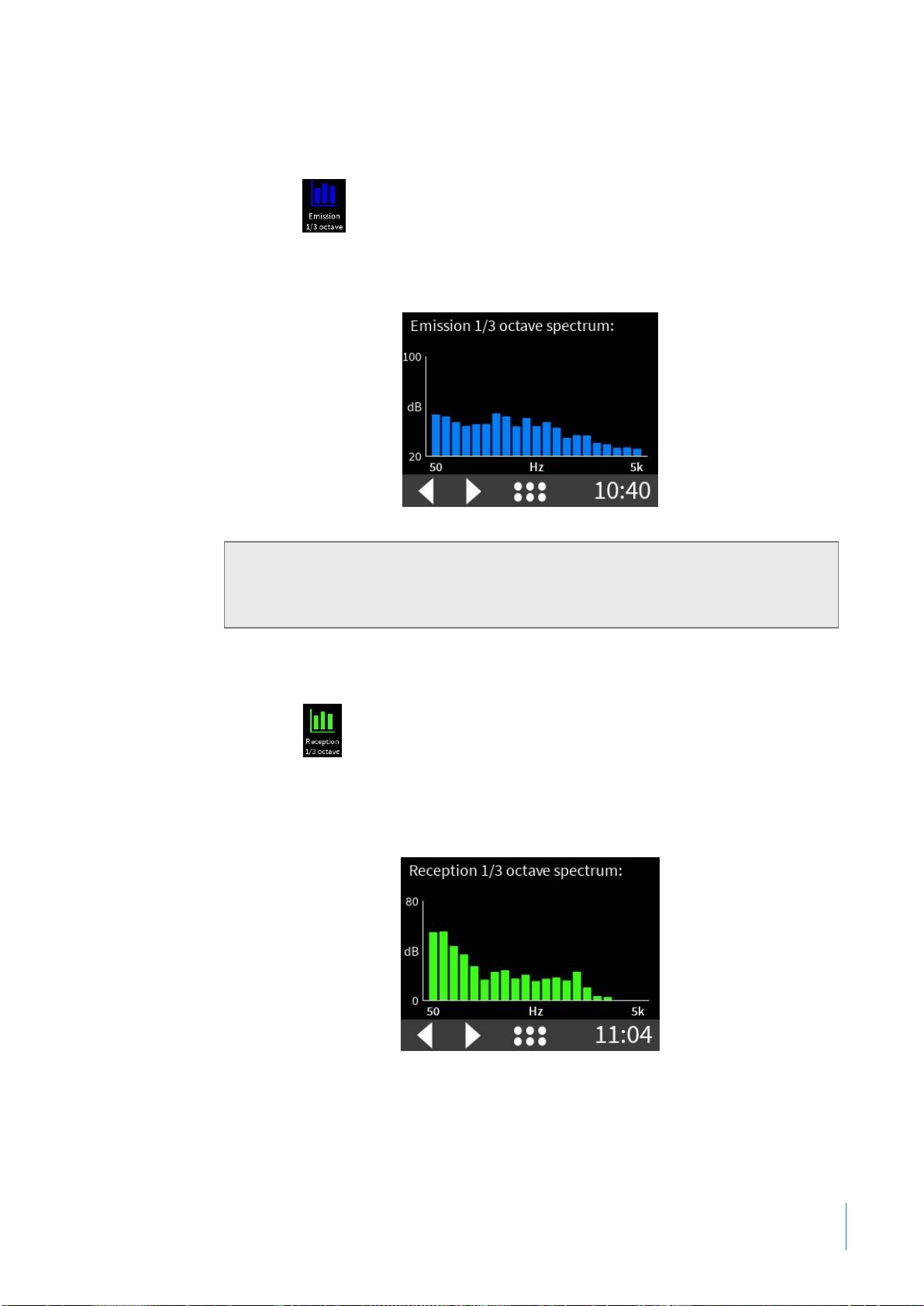
4.3.4 1/3 octave emission
Press the icon to display the real-time chart with the 1/3 octave spectrum
Emission levels (2) measured by the LF010 limiter’s main sensor in each 1/3
octave band between 50 Hz and 5 kHz.
4.3.5 1/3 octave reception
Press the icon to display the real-time chart with the 1/3 octave spectrum
Reception levels (2) calculated from the values measured by the main sensor and
taking into account the insulation entered into the LF010 limiter’s settings for
each 1/3 octave band between 50 Hz and 5k Hz.
NOTE(2):1/3 octave spectrum emission/reception corresponds to the
equivalent continuous sound level with moving integration time of 5 seconds
without frequency weighting.
18 Chapter 4 Touchscreen
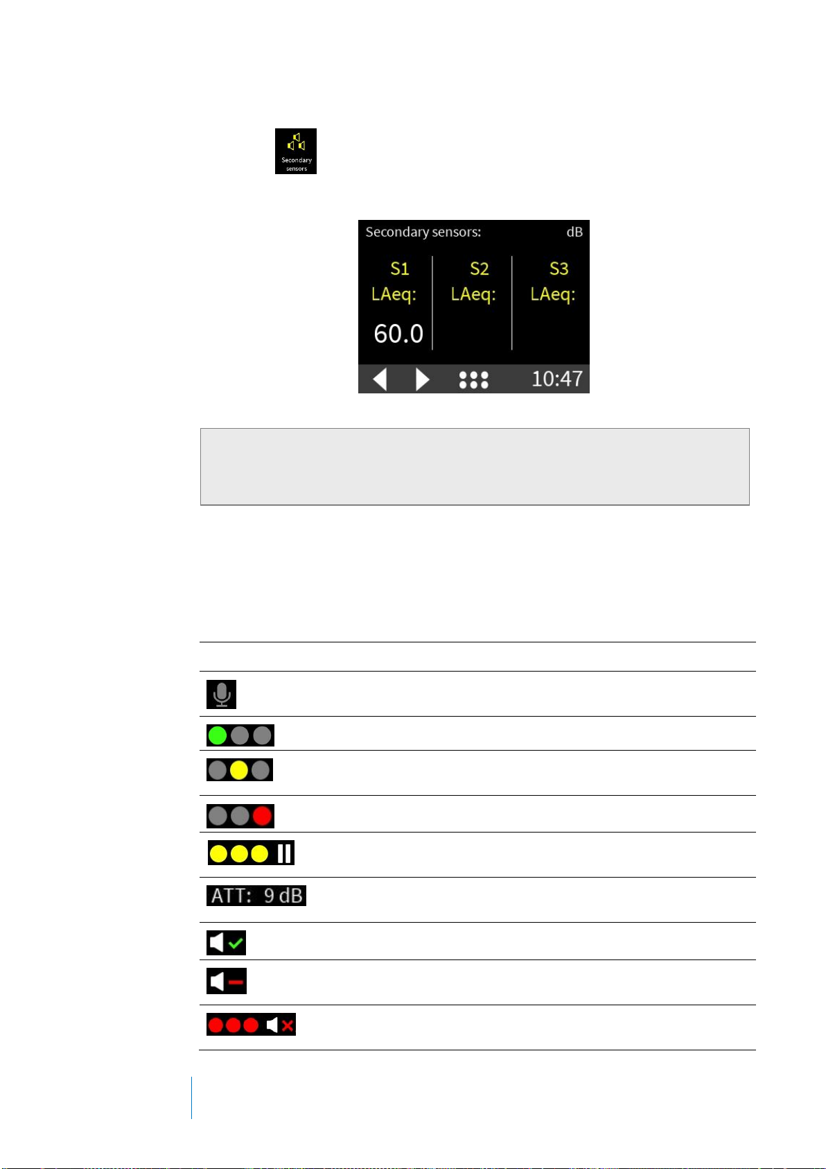
4.3.6 Secondary sensors
Press the icon to display, in real time, the LAeq secondary sensors(3)
measured by the different secondary sensors connected to the LF010 limiter (up
to a maximum of 3 sensors).
4.3.7 Indicator legends
The different information screens described in section 4.3 may feature the
following indicators depending on the status of the LF010 limiter.
INDICATOR
STATUS
Active Singer mode. Singer mode prevents major attenuations caused by
uncompensated microphone signals present in the musical signal.
The LF010 applies no attenuation to the sound signal level
The LF010 applies a deviation of between 1 and 7 dB to the sound signal
level
The LF010 applies an attenuation of above 7 dB to the sound signal level
Attenuation paused. The limiter detects no input audio signal and maintains
the current attenuation in order to apply it when the audio signal returns.
Indicator of the attenuation level in dB applied by the LF010 limiter to the
audio signal.
The limiter is working at optimal configuration.
Decrease the volume! The limiter is not working at optimal configuration.
The input signal level is too high and should be reduced.
MUTE: The limiter does not play the music signal entered into the AUDIO
INPUT [7 and 8]. The limiter enters this status if:
NOTE(3):The LAeq Secondary sensors correspond to the equivalent
continuous sound level with consecutive integration time of 4 seconds with
frequency weighting A.
Table of contents
Other CESVA Recording Equipment manuals


