CETAC Aridus II User manual

CETAC Aridus II™ Desolvating Nebulizer
System
Manual Part Number 480144 rev2
Operator’s Manual

COPYRIGHT
© 2009, 2011 CETAC Technologies
480144 rev2 , August, 2011
CETAC Technologies authorizes its customers
to reproduce, transmit, or store this document
in its entirety, including this page, for the
express purpose of installing, operating, or
maintaining the product described herein.
CETAC Technologies
Customer Service & Support
14306 Industrial Road
Omaha, Nebraska 68144, USA
Phone (800) 369-2822 (USA only)
Phone (402) 733-2829
Fax (402) 733-1932
E-mail [email protected]
REVISIONS
CETAC Technologies strives to provide the
scientific community with an unparalleled
combination of effective technology and
continuing value. Modular upgrades for
existing instruments will continue to be a
prime consideration as designs progress.
CETAC Technologies reserves the right to
revise this document and/or improve
products described herein at any time without
notice or obligation. Warranty registration
entitles the named owner exclusively to
manual change pages/new editions as they
are published.
TRADEMARK ACKNOWLEDGEMENTS
DuPont™, Kapton®, Teflon®, Tefzel® and
Viton® are trademarks or registered
trademarks of E.I. du Pont de Nemours and
Company.
All other marks are the property of their
respective owners.

3
Contents
1Introduction ........................................................................................................... 5
About This Book..................................................................................................................... 6
Aridus II™System Overview..............................................................................................6
Aridus II™ Specifications.................................................................................................... 7
Where to Go for More Information................................................................................ 8
2Preparing for Installation..................................................................................9
Choosing a Location..............................................................................................................9
Space Requirements......................................................................................................... 9
Power Requirements........................................................................................................ 9
ICP-MS Requirements........................................................................................................10
Gas Requirements ...............................................................................................................10
Unpacking the Aridus II™.................................................................................................11
Aridus II™Packaging...........................................................................................................11
3Installing the Aridus II™ .................................................................................. 13
Establishing External Connections ..............................................................................13
Connecting the Aridus II™to the Power Source .................................................13
Connecting the Aridus II™to the ICP-MS...............................................................13
Connecting the Aridus II™Drain Tubing....................................................................17
Connecting the ASX-112FR Autosampler to the Power Source......................17
Connecting the ASX-112FR Autosampler to the Host Computer ...................18
Connecting the Nebulizer to the Aridus II™..............................................................18
QuickWash Fast Washout Accessory..........................................................................21
4Verifying Installation ....................................................................................... 23
Initial Operating Procedure ............................................................................................23
ICP-MS Operation ................................................................................................................24
System Optimization..........................................................................................................24
Aridus II™Optimization Procedure..............................................................................24
5Using the Aridus II™ Desolvating Nebulizer System............................... 27
Establishing Optimal Operating Conditions ............................................................27
Establishing the Lab Environment ..........................................................................27
Replacing Aridus II™Components................................................................................28
Sample Transfer Line: Teflon®-Lined PVC Tubing ..........................................28
Peristaltic Pump Tubing: 3-Stop Gray/Gray 1.3mm I.D. ..............................28
Startup Procedure...............................................................................................................28
Shutdown Procedure .........................................................................................................29
Temperature Controller Operation .............................................................................29
Switching from Organic Samples to Aqueous Samples and Aqueous
Samples to Organic Samples..................................................................................30
6Maintaining the Aridus II™ ............................................................................. 31
Cleaning the Aridus II™......................................................................................................31
Daily External Cleaning................................................................................................31
Daily Internal Cleaning.................................................................................................32

ASX-520 Autosampler Operator’s Manual
Contents
4
Maintaining the Nebulizer and Spray Chamber.....................................................32
Using the C-Flow PFA Nebulizer Flush Kit ...........................................................33
Main Fuse Replacement....................................................................................................33
Spray Chamber and Desolvator Fuse Replacement.............................................34
Rinse Procedure for the Membrane Desolvator....................................................34
Removal of the Membrane Desolvator Modular Assembly ..............................35
Cleaning the Membrane Desolvator............................................................................39
7Troubleshooting the Aridus II™ .................................................................... 43
Temperature Controller Problems..............................................................................43
Temperature controllers and gas flow controllers do not illuminate. ....43
Display of temperature controller reads “Er 4.”................................................43
Temperature controller reads room temperature...........................................44
Temperature controller stops illuminating.........................................................44
Gas Flow Controller Problems.......................................................................................44
Sweep gas controller does not read zero..............................................................44
Argon sweep gas controller will not provide a reading of 3.0 or reading
is unstable..................................................................................................................44
Nitrogen gas controller will not provide 20 mL/min of nitrogen flow or
flow is unstable........................................................................................................44
Nebulizer / Plasma Problems ........................................................................................44
Poor and/or unstable aerosol generation ...........................................................44
Sample flow rate problems .........................................................................................45
Poor precision...................................................................................................................45
High elemental oxide levels ........................................................................................46
Excessive nitrogen-containing polyatomic ion interferences......................46
Nebulizer self-aspiration stops..................................................................................46
Plasma Problems.................................................................................................................46
Plasma flickers excessively or is unstable.............................................................46
Returning the Product to CETAC for Service ..........................................................47
Shipping the Product .....................................................................................................47
Product Warranty Statement....................................................................................47
Returned Product Procedures ...................................................................................48
Returned Product Warranty Determination ......................................................48
8Safety and Regulatory Information.............................................................. 51
Characteristics......................................................................................................................51
Environmental Characteristics .................................................................................51
Electrical Characteristics.............................................................................................52
Safety Notices........................................................................................................................53
Power Cord Set Requirements and Maintenance .............................................53
Mains Disconnect.............................................................................................................53
Cleaning Instructions.....................................................................................................54
Operating Environment................................................................................................54
Explanation of Caution and Warning Notices....................................................55
Avertissements en Français............................................................................................56
Electromagnetic Interference........................................................................................58
Explanation of Regulatory Marks.................................................................................58
9Glossary ................................................................................................................ 59

5
1Introduction
The Aridus II™ Desolvating Nebulizer System is designed primarily for ICP
mass spectrometry. The Aridus II™ incorporates a C-Flow PFA microconcentric
nebulizer, which provides low sample flow rates (approx. 50, 100, or 200
microliters/min.). The nebulizer is constructed entirely of inert materials and
is suited for use with acidic and alkaline solutions. Solutions may contain nitric
acid (HNO3), hydrochloric acid (HCl), hydrofluoric acid (HF), or ammonium
hydroxide (NH4OH).
Sensitivity is improved with the Aridus II™ system by enhancing analyte
transport efficiency and reducing solvent loading to the plasma. With
conventional pneumatic nebulization, injected water vapor causes oxide and
hydride polyatomic ion interferences in ICP-MS; organic solvent vapor loading
causes carbide polyatomic ion interferences as well as plasma instability and
carbon deposition on ICP-MS sampling cones. Using the Aridus II™ system for
sample introduction greatly reduces these problems. It is strongly noted that
the degree of sensitivity enhancement is dependent on the type of ICP-MS used
and the area of application.
Functionally, liquid sample is nebulized into a PFA spray chamber using a
C-Flow PFA microconcentric nebulizer operating at a sample uptake rate of
approximately 100 µL/min and an argon nebulizer gas flow rate of 0.7 to 1.1
L/min. The spray chamber is heated to help reduce the formation of solvent
droplets inside the spray chamber. The spray chamber is also drained by a
built-in peristaltic pump. The nebulizer gas flow then transports the aerosol
from the spray chamber to a heated inert fluoropolymer tubular membrane.
Solvent vapor passes through the membrane and is removed by an exterior
flow of Ar gas (sweep gas). Analyte continues through the middle of the
membrane tube to the ICP-MS instrument. An external view of the Aridus II™
Nebulizer System is shown in Figure 1-1.

Aridus II™ Operator’s Manual
6
About This Book
This document describes the procedures for installing, using, and maintaining
the nebulizer system.
This manual covers the following products:
CETAC Aridus II™ Desolvating Nebulizer System
CHEMICAL INJURY HAZARD
The Aridus II™ Desolvating Nebulizer System is intended for use only by
qualified operators who have been trained in safe laboratory practices.
Make sure you know the hazards associated with all of the chemicals you
are using, and take the appropriate precautions. Exposure to laboratory
chemicals may result in serious injury.
Aridus II™System Overview
Figure 1-1. Aridus II™Desolvating Nebulizer System.
WARNING

Aridus II™ Operator’s Manual
Chapter 1: Introduction
7
The following standard components/accessories are included with each
Aridus II™ system:
ICP-MS interface kit: All parts to interface to the operator’s ICP-MS,
including torch adapter, fittings, and tubing.
Rinse kit: Contains membrane rinse accessories and a tubing kit that
connects to the necessary ports.
Spare fuse kit: Contains replacement fuses for the Aridus II™.
Gas-line tubing kit: Contains all the necessary tubing to interface the
argon sweep gas and nitrogen addition gas to the Aridus II™.
C-Flow PFA Nebulizer: One low-flow microconcentric nebulizer. A 100
microliter/min nebulizer is standard. A 50 microliter/min or a 200
microliter/min nebulizer are also available.
Nebulizer Flush Kit: Flush kit for cleaning the C-Flow PFA nebulizer.
NOTE:
Contact CETAC Technologies if you need additional accessories or added
features to integrate the Aridus II™with your analytical system or if your
laboratory has unique requirements. Research and development of new
features and accessories for the Aridus II™, often inspired by customer
requests, is a continuing activity of CETAC Technologies.
Aridus II™ Specifications
Nebulizer: CETAC C-Flow PFA, 50, 100 or 200 µL/min
Inert Desolvating Membrane:
•Ar Sweep Gas: 0 to 8.0 L/min
•Nitrogen Gas: 0 to 50 mL/min
•Membrane Oven Temperature: 160°C
Spray Chamber: PFA with pumped drain
•Spray Chamber Temperature: 110°C
Voltage (Switch-Selectable):
•120 VAC +/- 10%, 50/60 Hz, 6A
•220 VAC +/- 10%, 50/60 Hz, 3A
Dimensions (Without Autosampler):
•33.6 cm W x 24.8 cm H x 55.9 cm D (13.2 in W x 9.8 in H x 22 in D)
•Weight: 10.5 kg (23.1 lbs)

Aridus II™ Operator’s Manual
8
Where to Go for More Information
In addition to this manual, you can refer to the following resources:
New versions of this manual may be available under “Service and Support”
on CETAC’s Web site:
www.cetac.com
CETAC Technologies Customer Service and Support:
Phone: 1 (800) 369-2822 (USA only)
1 (402) 733-2829
Fax: 1 (402) 733-1932
E-mail: custse[email protected]
The software and hardware manuals for the ICP-MS instrument you are
using.

9
2Preparing for
Installation
Before you install the Aridus II™nebulizer system, you should evaluate the
physical arrangement of the laboratory to choose a suitable location. Once you
choose a location, you must carefully unpack the system prior to beginning the
installation.
Choosing a Location
Choosing a location for the Aridus II™involves evaluating the laboratory
environment for the availability of space and power. For the Aridus II™to
function optimally, the location you select must meet specific requirements
associated with each of these items. The following sections discuss space and
power requirements.
Space Requirements
Most analytical applications benefit from the shortest sample flow path. A one
meter length of Teflon® lined PVC tubing is provided to connect the Aridus II™
to the ICP-MS torch. Place the Aridus II™sample out port less than one meter
from the ICP-MS torch. The system without the ASX-112FR autosampler is 34
cm x 25 cm x 56 cm (W x H x D). Adequate space should be allowed for proper
ventilation.
Power Requirements
Place the Aridus II™within 1.2 meters of the power outlet. The Aridus II™is
provided with a voltage selection switch on the bottom panel, right front. The
voltage may be selected as either 100-120 VAC +/- 10%, 50/60 Hz, 6A or 220-
240 VAC +/- 10%, 50/60 Hz, 3A. See Figure 2-1.

Aridus II™ Operator’s Manual
10
Figure 2-1. Voltage Selection Switch
SHOCK AND FIRE HAZARD
The system must be plugged into an outlet which has a protective ground
connection.
Ensure that you position the system so that the location where the power
supply cord plugs into it is easily accessible (is not blocked) and it can be
quickly disconnected if needed. In case of hazard, the system should be
disconnected from the power source.
Do not apply power until ready to operate the system.
ICP-MS Requirements
To achieve optimum performance with the Aridus II™, the ICP-MS system must
meet factory specifications from your vendor and be in good operating
condition. Check the ICP-MS performance using the standard sample
introduction system before Aridus II™installation. If the sensitivity, oxide ratios
and overall performance do not meet instrument specifications, consult the
ICP-MS Operator’s Manual. If ICP-MS performance specifications are met, then
begin installation of the Aridus II System.
In order for the C-Flow PFA nebulizer to properly self-aspirate, a minimum
argon gas pressure of 420 kPa (60 psi, 4.2 bar) is required in the nebulizer gas
line. Ensure that the Ar gas supply for the C-Flow PFA nebulizer is from a
known, good supply. The argon nebulizer gas supply from the host ICP-MS is
typically used for the C-Flow nebulizer.
Gas Requirements
The argon gas supply for the Aridus II™sweep gas may be teed in from the
main ICP-MS instrument argon gas supply. Nitrogen gas must be supplied from
an external source at a pressure of at least 350 kPa (50 psi, 3.5 bar). Nitrogen
with a minimum purity of 99.995% should be used.
WARNING

Aridus II™ Operator’s Manual
Chapter 2: Preparing for Installation
11
Unpacking the Aridus II™
Inspect external packaging upon receipt for signs of physical damage from
rough handling or abuse during shipment. Inspect all items during unpacking
and notify the carrier immediately of any visible or concealed damage. Remove
packing checklist from the shipping container, and check off items against it.
Leave accessories in the packing until you are ready to install them on the
Aridus II™.
Aridus II™Packaging
The Aridus II™ system is shipped in several containers:
Once container holds the Aridus II™ Desolvating Nebulizer System.
A second container holds the 15 L trap bottle, the ICP-MS interface kit, and
the Aridus II™completion kit. This container also holds the QuickWash fast
washout accessory, if ordered.
A third container holds the ASX-112FR autosampler, if ordered.
If the system is shipped or removed from storage during cold weather, allow
the packaged equipment to equilibrate to room temperature before opening
and exposing to warm, humid air. It is usually sufficient to provide four to eight
hours for this purpose.
EQUIPMENT DAMAGE FROM CONDENSATION
If condensation forms on or inside the Aridus II™, allow it to dry thoroughly before
connecting it to a power source and operating it. Failure to do so may cause
equipment damage.
NOTE
Keep the factory packaging for use in case the product ever needs to be
returned or shipped to another location.
CAUTION

Aridus II™ Operator’s Manual
12
This page is intentionally blank.

13
3Installing the
Aridus II™
To install the Aridus II™, you must complete the tasks described in this chapter.
Ensure that the AC power is off (0 showing at the bottom edge of the
power switch) on the back of the Aridus II™before proceeding with
installation.
Establishing External Connections
The first step in the installation process involves connecting the Aridus II™to
the power source and to the ICP-MS instrument. The following sections
explain how to establish these connections.
Connecting the Aridus II™to the Power Source
Voltage-specified power cords are supplied with each Aridus II™.
Use only these power cords or exact replacements.
To connect the Aridus II™to a power source, plug the cord into the power
module located on the back panel of the Aridus II™. Then plug the cord into an
appropriate AC outlet (110 or 220 VAC ±10%, 50/60 Hz depending on the
voltage selection).
Connecting the Aridus II™to the ICP-MS
Depending on the ICP-MS manufacturer and model, a torch adapter is supplied
for interfacing the Aridus II™to the ICP-MS. Adapters are available for all ICP-
MS instruments.
1A length of ¼"O.D. Teflon®-lined PVC tubing is connected to the torch adapter.
Place the other end of this tubing onto the SAMPLE OUT port located on the
back of the Aridus II™. This end will be equipped with a threaded nut for
WARNING
WARNING
Aridus II™ Operator’s Manual
14
attachment to the threaded SAMPLE OUT port. The threaded nut should only
be finger-tightened onto the SAMPLE OUT port.
Make certain that the Teflon® lining in the sample out tubing is not blocking the
aerosol path to the ICP-MS torch. This can result in instability and lack of analyte
signal from the ICP-MS instrument.
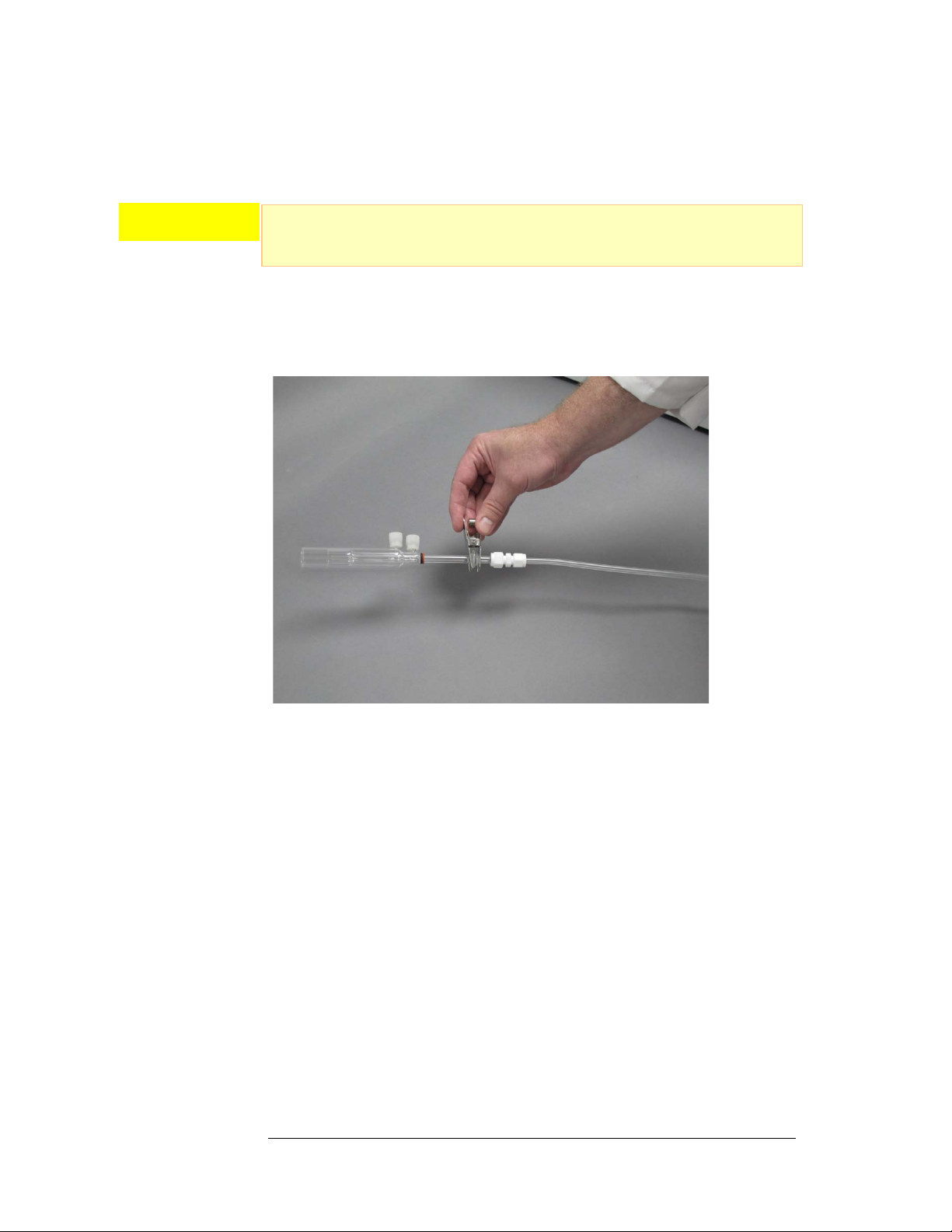
Attach the other end, containing the torch adapter, to the
ICP-MS torch/injector (Figure 3-1). Note that Figure 3-1 depicts the
attachment of the standard 12/5 glass joint. While this is a common type of
interface, the interface for the operator’s particular ICP-MS torch may be
different.
Figure 3-1. Connecting a torch adapter to the ICP-MS torch.
2The rinse port is shipped with a finger tight ¼-28 Tefzel®plug installed. The
rinse port should remain plugged except during cleaning/rinsing of the
membrane.
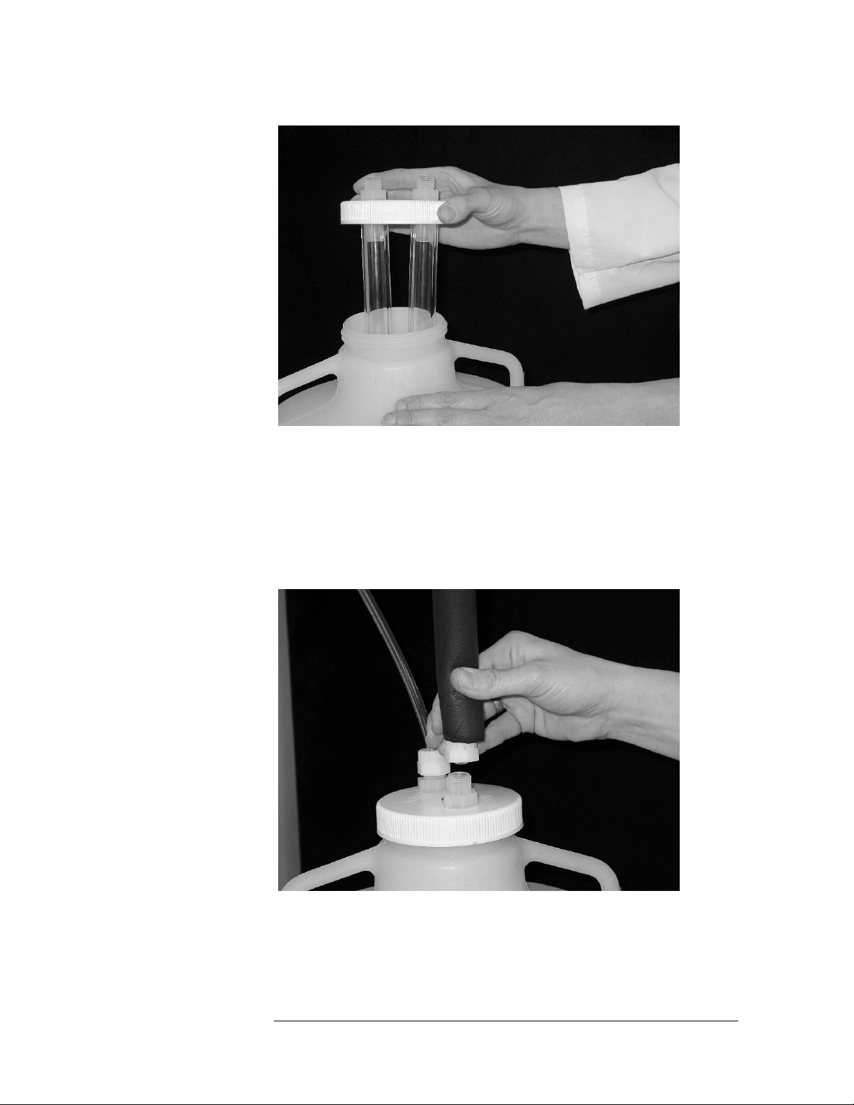
3Unscrew the lid of the 15 L trap bottle and carefully remove the packaging
around the two inner glass tubes. Replace the lid by screwing it down tight.
Then place the trap bottle on the floor or the bottom shelf of a laboratory cart.
See Figure 3-2.
CAUTION
Aridus II™ Operator’s Manual
Chapter 3: Installing the Aridus II™
15
Figure 3-2. Inner Glass Tubes – Trap Bottle.
4Screw the ½"adaptor end of the insulated Teflon® line to the corresponding
½"threaded PFA fitting for the SWEEP GAS OUT port. Attach the ½" adaptor of
the other end of this line to the corresponding ½"threaded fitting on the lid of
the 15 L trap bottle. Then connect the trap bottle exhaust line to the remaining
port on the trap bottle lid. This line will carry solvent vapors to the vent.
Exhaust should be appropriately vented at atmospheric pressure. See Figures
3-3a and 3-3b.
Figure 3-3a. Attachment of Insulated Sweep Gas Out Line to Trap Bottle.

Aridus II™ Operator’s Manual
16
Figure 3-3b. Attachment of Sweep Gas Out Exhaust Line to Trap Bottle.
5A minimum argon and nitrogen supply of 350 kPa (50 psi, 3.5 bar) is required
to operate the Aridus II™.The argon may be teed in from the ICP-MS
instrument argon supply using the ¼"union tee. Connect the ¼"O.D. tubing,
labeled ARGON and NITROGEN, to the respective supply ports on the back of
the Aridus II™. The ¼"O.D. tubing for each is simply inserted into the
corresponding press fit connectors. Simply push the tubing into its respective
connector until it is fully secure. Valves are supplied to turn off these gas
supplies when the Aridus II™is not in use (See Figure 3-4).
Figure 3-4. Attachment of Argon and Nitrogen Supply Lines.

Aridus II™ Operator’s Manual
Chapter 3: Installing the Aridus II™
17
Connecting the Aridus II™Drain Tubing
There is one liquid drain line to install on the back of the Aridus II™unit. To set
up this drain line:
1Obtain the peri-pump tubing kit from the Aridus II™completion kit.
2One bag inside the peri-pump tubing kit contains pre-cut tubing attached to
gray-gray color-coded peristaltic tubing. Remove this tubing from the bag.
3One of the tubing assemblies contains a tan-colored PEEK nut. Install the
PEEK nut into the threaded port labeled DRAIN on the back of the Aridus II™
unit. Tighten the PEEK nut so it is finger-tight.
4Install the gray-gray color-coded peristaltic tubing (already attached to the
PEEK nut via a length of Teflon®tubing) to the peristaltic pump mounted on
the back of the Aridus II™unit. Note that liquid from the drain port should flow
to the bottom of the peristaltic pump and out the top to waste. This is shown
by the arrows next to the pump.
5The outlet of the drain line may be placed in a suitable waste receptacle (such
as a beaker).
6Close the shoe of the peristaltic pump and adjust the tension against the pump
rotor head with the spring-loaded screw.
Connecting the ASX-112FR Autosampler to the
Power Source
To connect the ASX-112FR autosampler to a power source:
A voltage-specific external desktop power supply is supplied with each ASX-
112FR autosampler.
To connect the autosampler to a power source, plug the external desktop
power supply cord into the power connector located on the back panel of the
autosampler. Then, plug the power supply’s power cord into the power supply
and into a 100–240-VAC ±10%, 50/60-Hz utility power outlet.
It is important to use the appropriate power cord for your country. Contact
CETAC Technologies if you need a different power cord.
FIRE AND SHOCK HAZARD
Use only the provided desktop power supply. The power supply must be
plugged into an outlet which has a protective ground connection.
WARNING
Aridus II™ Operator’s Manual
18
Connecting the ASX-112FR Autosampler to the Host
Computer
You cannot operate the ASX-112FR autosampler until you establish a
communications interface between the autosampler and the host computer. It
is through this interface that the host computer directs the operation of the
ASX-112FR autosampler. Before connecting the ICP-MS, ensure the correct dip
switches are set for the ICP-MS interface, as described in the ASX-112
Autosampler Operators’ Manual. The ASX-112FR autosampler supports the
following three communications protocols:
The serial (RS-232C) protocol is the standard configuration. There is an
RS-232C serial port on the ASX-112FR, and a serial interface kit is shipped
with the autosampler.
The USB protocol is an optional configuration.
The parallel (IEEE-488) protocol is less common than the serial
configuration or USB. An IEEE-488 interface kit is available as an optional
accessory to the ASX-112FR. (Refer to the ASX-112FR Autosampler
Operator’s Manual for further instructions.)
Connecting the Nebulizer to the Aridus II™
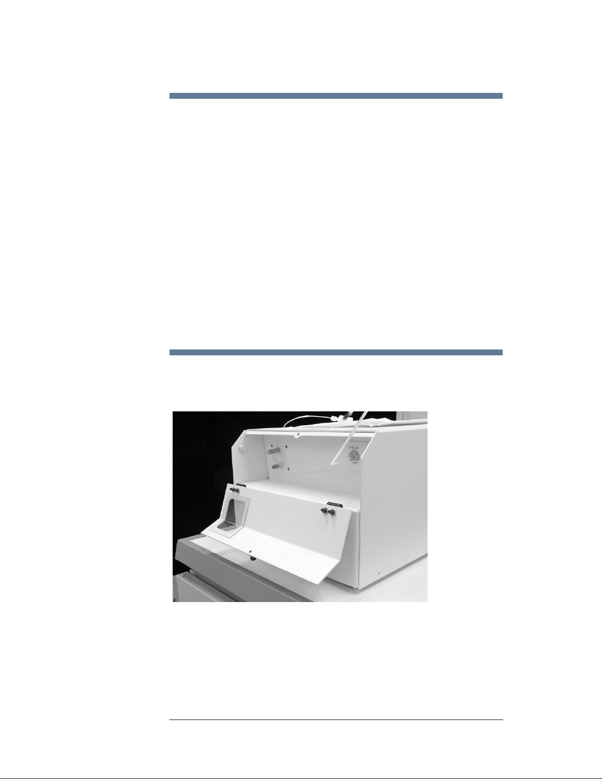
1Loosen the top thumb screw on the front of the Aridus II™and open the front
door by pulling downward. See Figure 3-5.
Figure 3-5. Front Door of Aridus II – Open.
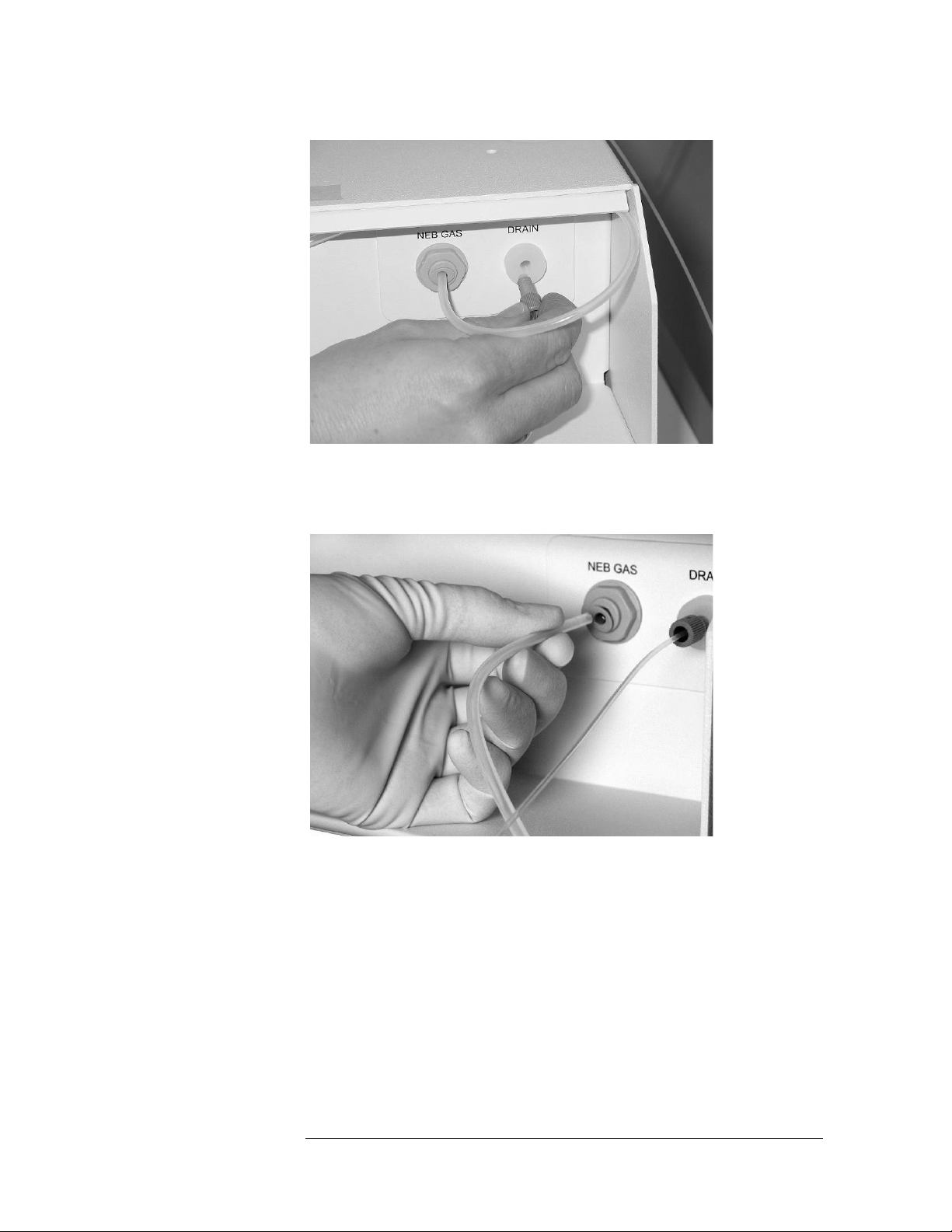
2Attach one end of the spray chamber drain line to the bottom of the spray
chamber. Attach the other end to the port labelled DRAIN. See Figure 3-6.
Aridus II™ Operator’s Manual
Chapter 3: Installing the Aridus II™
19
Figure 3-6. Attachment of Spray Chamber Tubing to Drain Port.
3Insert the nebulizer gas line (4mm O.D. tubing ) into the press-lock fitting
labelled NEB-GAS. See Figure 3-7.
Figure 3-7. Attachment of 4mm O.D. Tubing to NEB GAS Port.

Aridus II™ Operator’s Manual
20
4Connect the other end of the nebulizer gas line to the side gas port of the
C-Flow PFA nebulizer. Insert the 4 mm tubing into the PFA nut and finger-
tighten the nut. See Figure 3-8.
Figure 3-8. Attachment of Nebulizer Gas Line to Gas Port of C-Flow PFA
Nebulizer.
5Insert the C-Flow PFA nebulizer into the spray chamber port. See Figure 3-9.
Ensure that the nebulizer is fully inserted through both o-rings.
Figure 3-9. Insertion of C-Flow PFA Nebulizer into Spray Chamber.
6Carefully set the C-Flow uptake line through the sample inlet notch in the
upper left front of the Aridus II™door. See Figure 3-10. Attach the sample probe
assembly to the ASX-112FR probe holder. (Refer to the ASX-112FR Operator’s
Manual for further instructions.)
Table of contents


