CETEC Sparta 625A User manual


www.SteamPoweredRadio.Com
I
,,...
-----------------....."'II
I
I
I
I
I
I
I
I
I
I
I
I
I
I
I
I
I
I
TECHNICAL
MANUAL
Model
625A
FM
Transmitter
PROPRIETARY
NOTICE
Sparta Electronic
Corporation
proprietary
data
is
contained
herein.
Neither
this
document
nor
the
information
contained herein shall be disclosed
to
others
for
manufacturing
or
any
other
purpose except
as
authorized in
writing
by
Sparta Electronic Corporation.
C1974
098-7042 25.00
!5B!51
FLORIN·P
AKIN
ROAD
ACRAM
NTC,
CALIFORNIA
A OIVI
IO
N Of
CO
M
..
U
T[R
(
QUl,.M(NT
CORl'ORATION
aa
www.SteamPoweredRadio.Com
I
I
I
I
I
I
I
I
I
I
I
I
I
I
I
I
I
I
I
WARNING
THIS UNIT CONTAINS HIGH
VOLTAGE,
HIGH CURRENT
POWER
SUPPLIES.
Potentials up to 8000 volts* at lethal
current
levels are present and exposed to mainte-
nance personnel working with power
on
and
interlocks defeated.
When maintenance requires
working
with
power on and
unit
open, exercise extreme
caution. Stand on insulated surface. Work
with only one hand inside unit. Use only high
voltage insulated tools. Have second person
standing by at all times.
*
Depending upon
transmitter
being used.
~(p~Lf~
ELECTRONIC CORPORATION
www.SteamPoweredRadio.Com
I
·I
I
I
I
I
I
I
I
I
I
I
I
I
I
I
I
I
I
Model
625A
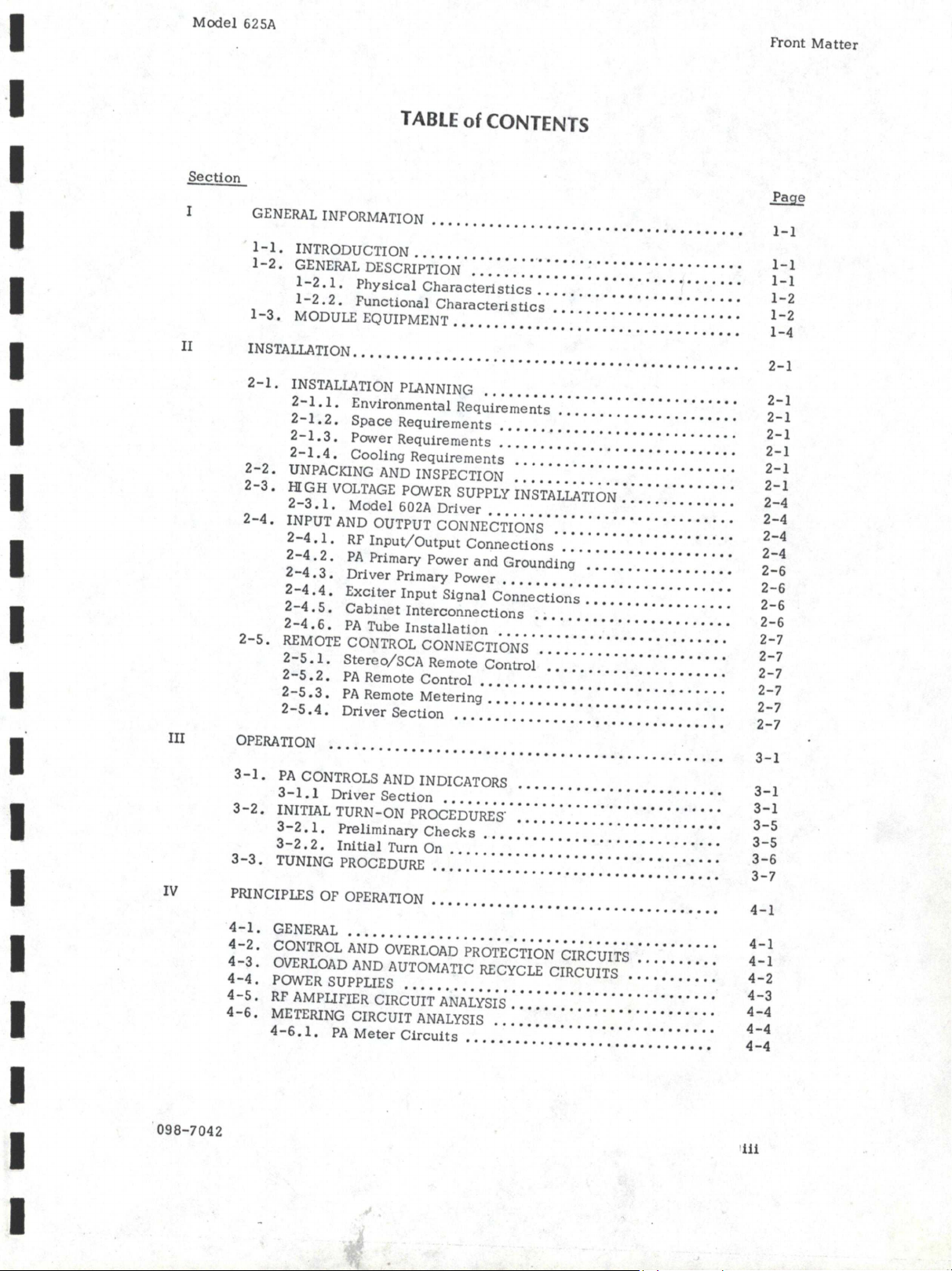
TABLE
of
CONTENTS
Section
I
GENERAL
INFORMATION
.•....•.•..•••••••••••••••••••••••••••
l-1.
INTRODUCTION
....••.•••••.••••••..••.•••••••••••.••••
l-2.
GENERAL
DESCRIPTION
•••••••••••••••••••••••••••••.•••
l-2
.1.
Physical
Characteristics
•••••••.•.••..••••.••••••
1-2.2.
Functional
Characteristics
••••••••.••••••.••.••••
l-3.
MODULE EQUIPMENT
•••.••.•••••••••.••••••••••••••••••
II
INSTALLATION
..••••••••••••••.•••••••••.•••••.•••••••.••••••
III
IV
098-7042
2-1.
INSTALLATION PLANNING
••••..•••••••.••••••.••••••••••
2-1.
l.
Environmental
Requirements
..•...•.•••••.••••••••
2-1.
2.
Space
Requirements
••.••••••••..•••••••.•••.••••
2-1.3.
Power
Requirements
•.••••••••••..•••••••••••••••
2-1.
4.
Cooling
Requirements
..••••.•.••••••••••••••••••
2-2.
UNPACKING
AND
INSPECTION
•••.•..•••..•••••••.••..•••
2-3.
HIGH
VOLTAGE
POWER SUPPLY INSTALLATION
•••••••.•••••.
2-3.
l.
Model
602A
Driver
•....•••.•.••••••.••.••.••••••
2-4.
INPUT
AND
OUTPUT CONNECTIONS
..••••••••••••••••••••
2-4.
l.
RF
Input/Output
Connections
•••••••••••••••••••••
2-4.
2.
PA
Primary
Power
and
Grounding
•••••••••.••••••••
2-4
.3.
Driver
Primary
Power
••••••••••••.•••••••••••.•••
2-4
.4.
Exciter
Input
Signal
Connections
.••••••••••••••.••
2-4.
5.
Cabinet
Interconnections
••..••••••••••••••..••••
2-4.
6.
PA
Tube
Installation
...••••.•••••••••••••••...•.
2-5.
REMOTE
CONTROL CONNECTIONS
.•••..••.•••••••••.••••
2-5
.1.
Stereo/SCA
Remote
Control
••.•.•••••••••••••••••
2-5.
2.
PA
Remote
Control
•••.••••.•••••••••.••••••.•.•.
2-5.
3.
PA
Remote
Metering
.••••••••••••••••••••••••••••
2-5
.4.
Driver
Section
••••••.••••••••••••••••••••••••••
OPERATION
••.••••••••••.••.••••••.••••••.•••••••••••••••••
3-1.
PA
CONTROLS AND INDICATORS
•••••.•••••.•••••••••••••
3-1.1
Driver
Section
••.•.•••••••••••••••.•••••••••••••
3-2.
INITIAL TURN-ON PROCEDURES.
••.•••••••.•.••.•••.•••••
3
-2
•l ,
Preliminary
Che
ck
s
••••.••••••.••••••••••••••.••
3-2.
2.
Initial
Turn On
...•.••••.•••••.••••••••••••.•••.
3-3.
TUNING PROCEDURE
.••..••••••••••••••••••••••.•••••••
PRINCIPLES OF
OPERATION
•••••.•••••••••••••••••••••••••••••
4-1.
GENERAL
••..•••..•••••.••••.•••••.••••.••••••••••••.•
4-2,
CONTROL
AND
OVERLOAD
PROTECTION CIRCUITS ,
.•••.••••
4-3.
OVERLOAD
AND
AUTOMATIC
RECYCLE
CIRCUITS
••.•••.••••
4-4.
POWER SUPPLIES
••..••..•....•••••.••••••••••••••
,
••.•
4-5.
RF
AMPLIFIER CIRCUIT
ANALYSIS
..•••••••••.•••••••••••••
4-6.
METERING CIRCUIT
ANALYSIS
.•••••••••.•.••••••••••••••
4-6
.1.
PA
Meter
Circuits
••.•••••••••••••••••••••••••••
Front
Matter
l-1
l-1
l-1
1-2
l-2
l-4
2-l
2-1
2-l
2-l
2-1
2-1
2-1
2-4
2-4
2-4
2-4
2-6
2-6
2-6
2-6
2-7
2-7
2-7
2-7
2-7
2-7
3-l
3-l
3-l
3-5
3-5
3-6
3-7
4-l
4-l
4-1
4-2
4-3
4-4
4-4
4-4
www.SteamPoweredRadio.Com
Model
625A
Section
V
VI
Figure
2-1
2-2
2-3
3-1
3-2
3-3
3-4
3-5
3-6
3-7
3-8
3-9
3-10
3-11
5-1
5-2
5-3
5-4
098-7042
4-7.
4-6.2.
4-6.3.
Power
Output
and
VSWR
measurement.
•.•.•.•••••••
PA
Filament
and
Elapsed
Time
Meter
Circuit.
•••....
POWER CONTROL
•••••.•...••••.•.••••••••••.••••.••..•
MAINTENANCE
•••.....•••.•••••••••••••.•.•.•••••••••••••••
5-1.
PERIODIC INSPECTION AND MAINTENANCE
••.••.•.•••••••
5-1.1.
Air
Filters
•••.••.••.•••••••••.•••••••••••.••••
5-1.
2.
Anode
Coolers
•...•...•.•.•..••.•..••..••.••.••
5-2.
REMOVAL
AND REPIACEMENT
OF
AMPLIFIER
TUBES
•••••••.•
5-3.
OVERLOAD
REIAY
ADJUSTMENT
.•..••..•••.••••••...•••.•
5-3.
1.
Driver
Section
Overload
Relay
Adjustment
•..••••.•
5-3.
2.
PA
Grid
Overload
•..••..••.••••••••.•••.•••••••
5-3
.3.
PA
Plate
Overload
............................
.
5-3
.4.
Automatic
Power
Control
Adjustment
•••.••••.•••••
5-3.
5.
VSWR
Adjustment
•.•••••.••••••.•••.•••.•••.•••
REPIACEABLE
PARTS
6-1.
ORDERING INFORMATION
•••••.•••••••.•.•••••••••••••••
6-2.
PARTS
LOCATION
•.••..•..•••••••••••••••••••••••••••••
6-3.
TABLES
OF
REPLACEMENT
PARTS
••••••••••.••••••••••••••
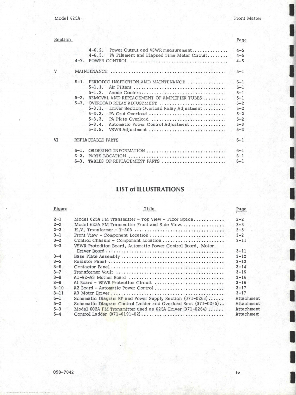
LIST
of
ILLUSTRATIONS
Title
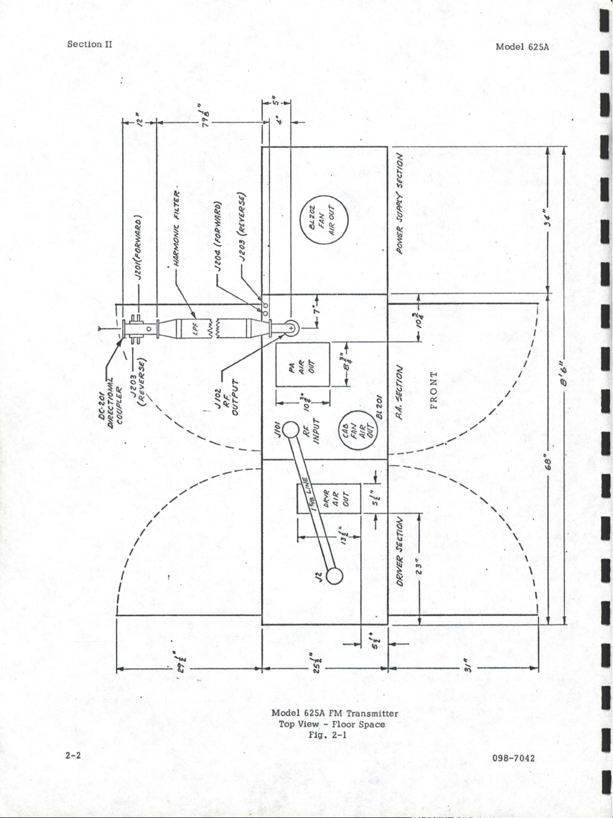
Model
625A
FM
Transmitter
-
Top
View -
Floor
Space
•••••••••••.
Model
625A
FM
Transmitter
Front
and
Side
View
.••••..•.•••..•••
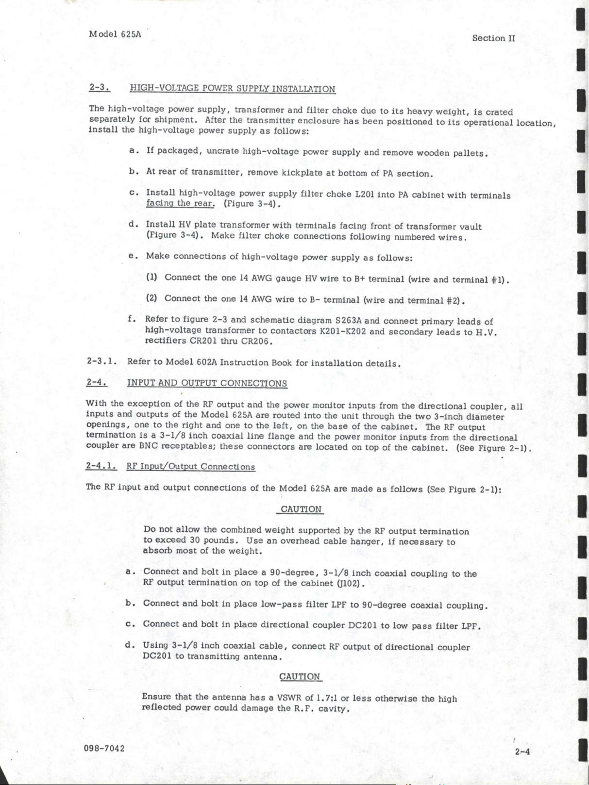
H.
V.
Transformer
-
T-203
••••••.••••••••.•••••••••••••.•.•••
Front
View -
Component
Location
.••.•.•••.•••••••••••••••••••
Control
Chassis
-
Component
Location
•••..•..••••••.••••••••.
VSWR
Protedtion
Board,
Automatic
Power
Control
Board,
Motor
Driver
Board
...••••••••.••..••••.•••••••••.••••••••.••.•••
Base
Plate
Assembly
•••..•.•••..•••.•••.••.•.•••••••••••.•••
Resistor
Panel
.•••••••••••••••.••••••••••••••••••••••••.•••
Contactor
Panel
.••.•••••••••••••••••••.••••••••••••••.•••••
Transformer
Va
ult
••••••.••••••.••••..••••••.••.•••••.•..•••
Al-A2-A3
Mother
Board
....•...•.•••..•••••••.••••••••.•••••
Al Board -
VSWR
Protection
Circuit
••......•.••••••••.••••••••
A2
Board -
Automatic
Power
Control
.••••••.•••.•.•.•••.•••••••
A3
Motor
Driver
.••.•....•.....•.••.••...•...••..•••..•.••••
Schematic
Diagram
RF
and
Power
Supply
Section
(071-0263)
••••••
Schematic
Diagram
Control
Ladder
and
Overload
Sect
(071-0265)
••
Model
602A FM
Transmitter
used
as
625A
Driver
(071-0264)
••••••
Control
Ladder
(O
71-0191-02)
••••••••.•••••••••••••••••••••••
Front
Matter
Page
4-5
4-5
4-5
5-1
5-1
5-1
5-1
5-1
5-2
5-2
5-2
5-2
5-3
5-3
6-1
6-1
6-1
6-1
2-2
2-3
2-5
3-2
3-11
3-11
3-12
3-13
3-14
3-15
3-16
3-16
3-17
3-17
Attachment
Attachment
Attachment
Attachmert
iv
I
I
I
I
I
I
I
I
I
I
I
I
I
I
I
I
I
I
I

www.SteamPoweredRadio.Com
I
I
I
I
I
I
I
I
I.
I
I
I
I
I
I
I
I
I
I
Mo
del
6
25
A
TA
BL
E
1-1
1-2
3-1
3- 2
3- 3
6- 1
6- 2
098-7042
{
LIST
of
TAB
L
ES
Titl
e
Phys
ica
l
Charac
t
eristics
.•..
.
•..••.•••••••.••••••••••.••••••••
Fu
nc
tio
n
al
Characteristics
•.•.••••.••••.••••.••••••••••••••••••
O
perating
Controls
and
lndicators
-
PA
Secti
on
•...•..••••••••••••
Typi
ca
l
Operating
Voltages
and
Currents
•••••••••••••••••••••••••
Effi
ciency
Curve
••••.••••.•••••••••••••.•••.•••••••••••••••••
List
of
Manufactures
••.••••..••••.••.••.••••.•••.•••••••••••.•
Re
pl
aceable
Parts
List
••.•
•
•••••••••••••••••••••••••••••••••••
'
Front
Mat
ter
1-2
1- 3
3- 3
3-9
3-10
6- 2
6-
3
V

www.SteamPoweredRadio.Com
I
I
I
I
I
I
I
I
I
I
I
I
I
I
I
I
I
I
I
Model
625A
1-1
. INTRODUCTION
SECTION I
G
ENERAL
INFORMATION
Section
I
This
manual
contains
information
required
to
install,
operate,
and
maintain
the
SPARTA
Model
625A
FM
Transmitter.
Section
I
describes
the
transmitter
and
lists
its
specifications,
Section
II
provides
installation
instructions,
Section
III
contains
operating
procedures
and
Section
IV
describes
the
principle
of
operation.
Maintenance
procedures
and
troubleshooting
diagrams
are
contained
in
Section
V,
and
replaceaole
parts
are
identified
and
listed
in
Section
VI
. A
complete
operating
and
servicing
manual
covering
the
Model
680
FM
Exciter
and
Model
602
FM
transmitter
is
provided
separately
.
1-2.
GENERAL
DESCRIPTION
The
Model
625A
FM
Transmitter
(Figure
2-2)
provides
an
output
of
25
kilowatts
in
the
frequency
range
from 88
to
108
MHz,
and
is
type-accepted
by
the
Federal
Communications
Commission
under
Part
73,
Broadcast
Services.
As
shown
in
figure
1-1,
the
transmitter
consists
basically
of
three
sections
. The
left-hand
section
contains
the
FM
exciter
and
driver,
together
with
associated
metering,
control
and
power
circuitry.
This
section
is
denominated
DRIVER
throughout
this
instruction
book
and
consists
of
a
complete
and
independent
one
2.5
K:N
transmitter,
model
602A .
The
second
section
contains
the
power
amplifier
(PA)
and
its
associated
metering,
control,
and
high
voltage
filtering
components
. The
right-hand
section
is
the
transformer
vault
and
it
contains
the
plate
transformer,
H .
V.
rectifiers
and
contactors
plate.
The
PA
cavity
is
cooled
by
a
high-speed
blowers
and
each
of
the
two
cabinet
sections
are
scavenged
of
incidental
warm
air
by
ventilating
fans
. The
circuit
design
of
the
blower
furnishing
air
to
the
PA
cavity
is
such
that
it
will
continue
to
run
for a
preset
interval
after
the
transmitter
is
shut
down
to
remove
residual
heat.
The
Model
625A
design
includes
such
features
as
automatic
power
control
and
automatic
overload
recycling.
Once
the
transmitter
has
been
tuned
to
its
authorized
rated
power
output,
the
automatic
power
control
circuit
maintains
this
RF
output
level
regardless
of
mains
power
fluctuations.
The
overload
recycle
circuit
automatically
restores
the
transmitter
to
normal
operation
following
a
momentary
current
overload
in
the
monitored
circuits
.
Consecutive
recycling
is
limited
to
three
times
within
30
seconds
following
the
operation
of
any
overload
relay.
If
the
overload
exists
after
a maximum
of
3
recycles,
the
transmitter
high-voltage
circuits
will
remain
off
until
the
overload
is
reset
manually.
Tally
lights
mounted
on
the
driver
and
PA
control
panels
are
triggered
by
their
associated
overload
relay
.
These
lamps
will
remain
lighted
after
a
momentary
overload
to
identify
the
circuit
where
the
overload
occurred.
Only
three
transmitti
ng
tubes
are
used
in
the
high-level
stages:
a
4X150A
tetrode
(driver),
a 5CX1500A
pentode
(driver) ,
an
d a 3CX15000A7
triode
(PA).
RF
excitation
is
provided
by
the
Model
680
FM
Exciter,
which
is
an
all-solid-state
unit
that
provides
monaural,
stereophonic
and
Subsidiary
Communications
A
uthorization
(SCA)
modes
of
operation
in
accordance
with
FCC
and
international
standards.
The M
odulation
m
ethod
is
"direct
FM"
with
no
mixers
or
multipliers
after
the
modulated
oscillator
.
Connections
are
provided
to
allow
remote
transmitter
mas
ter
start,
plate
power
on-off,
and
power
trim.
Provisions
are
also
included
for
remote
metering
of
PA
pla
te
voltage,
plate
current
and
power
output.
098-7042
1
-1
www.SteamPoweredRadio.Com
Mcx:lel 625A
Section
I
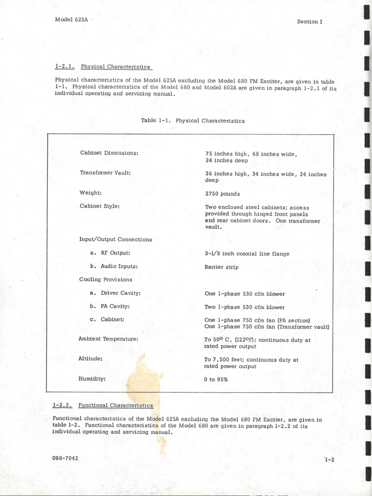
1-2
.1.
Physical
Characteristics
Physical
characteristics
of
the
Mcx:lel 625A
excluding
the
Model
680
FM
Exciter,
are
given
in
table
1-1.
Physical
characteristics
of
the
Mcx:lel
680
and
Mcx:lel 602A
are
given
in
paragraph
1-2
.1
of
its
individual
operating
and
servicing
manual.
Table
1-1.
Physical
Characteristics
Cabinet
Dimensions:
Transformer
Vault:
Weight:
Cabinet
Style:
Input/Output
Connections
a.
RF
Output:
b.
Audio
Inputs:
Cooling
Provisions
a.
Driver
Cavity:
b.
PA
Cavity:
c.
Cabinet:
Ambient
Temperature:
Altitude:
Humidity:
1-2.
2.
Functional
Characteristics
75
inches
high,
68
inches
wide,
24
inches
deep
36
inches
high,
34
inches
wide,
24
inches
deep
2750
pounds
Two
enclosed
steel
cabinets;
access
provided
through
hinged
front
panels
and
rear
cabinet
doors.
One
transformer
vault.
3-V8
inch
coaxial
line
flange
Barrier
strip
One
1-phase
530 cfm
blower
Two
1-phase
530
cfm
blower
One
1-phase
750 cfm
fan
(PA
section)
One
1-phase
750 cfm
fan
(Transformer
vault)
To
50°
C,
(122°F);
continuous
duty
at
rated
power
output
To
7,500
feet;
continuous
duty
at
rated
power
output
0
to
95%
Functional
characteristics
of
the
Model
625A
excluding
the
Model
680
FM
Exciter,
are
given
in
table
1-2.
Functional
characteristics
of
the
Model
680
are
given
in
paragraph
1-2.
2
of
its
individual
operating
and
servicing
manual.
098-7042
I
I
I
I
I
I
I
I
I
I
I
I
I
I
I
I
I
I
I
www.SteamPoweredRadio.Com
I
·I
I
I
I
I
I
I
I
I
I
I
I
I
I
I
I
I
I
Model
625A
Section
I
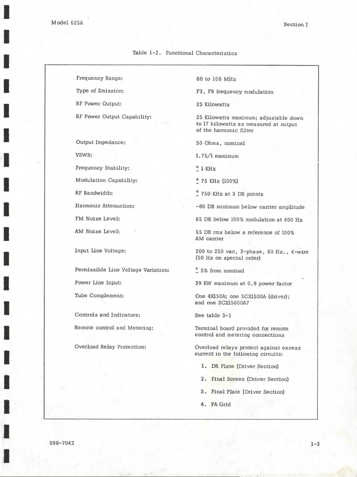
Table
1-2.
Functional
Characteristics
,
Frequency
Range:
Type
of
Emission:
RF
Power
Output:
RF
Power
Output
Capability:
Output
Impedance:
VSWR:
Frequency
Stability:
Modulation
Capability:
RF
Bandwidth:
Harmonic
Attenuation:
FM
Noise
Level:
AM
Noise
Level:
Input
Line
Voltage:
Permissible
Line Voltage
Variation:
Power
Line
Input:
Tube
Complement:
Controls
and
Indicators:
Remote
control
and
Metering:
Overload
Relay
Protection:
098-7042
88
to
108
MHz
F3,
F9
frequency
modulation
25
Kilowatts
25
Kilowatts
maximum;
adjustable
down
to
17
kilowatts
as
measured
at
output
of
the
harmonic
filter
50
Ohms,
nominal
I.
7
5/1
maximum
~
1
KHz
~
7
S
KHz
(100%)
~
750
KHz
at
3
DB
points
-80
DB
minimum
below
carrier
amplitude
65
DB
below
100%
modulation
at
400
Hz
55
DB
rms
below
a
reference
of
100%
AM
carrier
200
to
250
vac,
3-pha
se,
60
Hz.
,
4-wire
(SO
Hz
on
special
order)
~
5%
from
nominal
39
KY-I
ml;lximum
at
0.
9
power
factor
One
4Xl50A;
one
SCXlS00A
(driver);
and
one
3CX1S000A7
See
table
3-1
Terminal
board
provided
for
remote
control
and
metering
connections
Overload
relays
protect
against
excess
current
in
the
following
circuits:
1.
DR
Plate
(Driver
Section)
2.
Final
Screen
(Driver
Section)
3.
Final
Plate
(Driver
Section)
4.
PA
Grid
1-3

www.SteamPoweredRadio.Com
Model
625A
Section
I
Table
1-2.
Functional
Characteristics
(Continued)
Overload
Indicators:
5.
PA
Plate
6.
VSWR
One
overload
indicator
and
six
overload
tally
lights.
(See
table
3-1)
Other
Protective
Devices:
Eight
Panel-mounted
fuses
and
two
internal
circuit
breakers.
Two
additional
fuses
mounted
on
rear
panel
of
exciter.
1-3.
MODULE EQUIPMENT
The
Model
680
FM
Exciter
is
standard
equipment
and
provides
the
capability
of
monaural
FM
operation.
The
following
units,
which
are
available
from
SPARTA
ELECTRONIC CORPORATION
provide
the
Model
625A
with
the
capability
of
stereophonic
and
SCA
operation:
a.
Stereo
Generator
-
Model
682
b.
SCA
Generator
-
Model
683 (41
or
67
KHz)
When
operating
in
the
monaural
mode,
the
41
KHz
and
67
KHz
SCA
units
may
be
used
individually
or
simultaneously.
When
operating
in
the
stereophonic
mode,
the
41
KHz
generator
must
be
muted.
However,
the
67
KHz
generator
can
be
used
in
combination
with
the
stereo
generator
in
any
mode
of
operation
without
program
interruption
if
an
optional
5 KHz
filter
kit
is
installed.
The 5 KHz
filter
kit
(091-5971-01)
may
be
specified
for
initial
installation
by
SPARTA
ELECTRONIC
CORPORATION
or
it
can
be
added
to
the
SCA
module
at
a
later
date.
The
kit
consists
of
a
low-pass
filter
which
limits
the
SCA
input
band-width
to
5 KHz.
In
addition
to
the
input
filter,
the
sub-carrier
deviation
should
be
limited
to
6%
to
avoid
interference
with
the
stereo
channel.
098-7042
1-4
I
I
I
I
I
I
I
I
I
I
I
I
I
I
I
I
I
I
I
www.SteamPoweredRadio.Com
I
I
I
I
I
I
I
I
I
I
I
I
I
I
I
I
I
I
Model
625A
SECTION
II
INSTALLATION
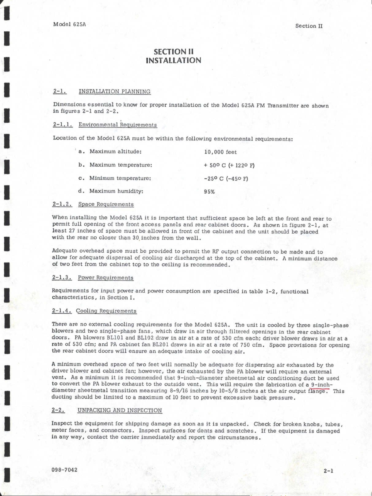
2-1.
INSTALI.ATION PI.ANNING
Section
II
Dimensions
essential
to
know
for
proper
installation
of
the
Model
625A FM
Transmitter
are
shown
in
figures
2-1
and
2-2.
2-1.1.
Environmental
Requirements
Location
of
the
Model
625A
must
be
within
the
following
environmental
requirements:
'
a.
Maximum
altitude:
10,000
feet
b.
Maximum
temperature:
+
500
C (+
1220
F)
c.
Minimum
temperature:
-250
C
(-450
F)
d.
Maximum
humidity:
95%
2-1.
2.
SEace
Requirements
When
installing
the
Model
625A
it
is
important
that
sufficient
space
be
left
at
the
front
and
rear
to
permit
full
opening
of
the
front
access
panels
and
rear
cabinet
doors.
As
shown
in
figure
2-1,
at
least
27
inches
of
space
must
be
allowed
in
front
of
the
cabinet
and
the
unit
should
be
placed
with
the
rear
no
closer
than
30,
inches
from
the
wall.
Adequate
overhead
space
must
be
pro
v
ided
to
permit
the
RF
output
connection
to
be
made
and
to
allow
for
adequate
dispersal
of
cooling
air
discharg
ed
at
the
top
of
the
cabinet.
A minimum
distance
of
two
feet
from
the
cabinet
top
to
the
ceiling
is
recommended.
2-1.
3.
Power
Requir
e
ments
Requirements
for
input
power
and
power
consumption
are
specified
in
table
1-2,
functional
characteristics,
in
Section
I.
2-1.4.
Cooling
Requirements
There
are
no
external
cooling
requirements
for
the
Model
625A. The
unit
is
cooled
by
three
single-phase
blowers
and
two
single-phase
fans,
which
draw
in
air
through
filt
e
red
openings
in
the
rear
cabinet
doors.
PA
blowers
BLl0l
and
B1102
draw
in
air
at
a
rate
of
530 cfm
each;
driver
blower
draws
in
air
at
a
rate
of
530 cfm;
and
PA
cabinet
fan
B1201
draws
in
air
at
a
rate
of
750
cfm.
Space
provisions
for
opening
the
rear
cabinet
doors
will
ensure
an
adequate
intake
of
cooling
air.
A
minimum
overhead
space
of
two
feet
will
normally
be
adequate
for
dispersing
air
exhausted
by
the
driver
blower
and
cabinet
fan;
however,
the
air
exhausted
by
the
PA
blower
will
require
an
external
vent.
As a minimum
it
is
recommended
that
9-inch-diameter
sheetmetal
air
conditioning
duct
be
used
to
convert
the
PA
blower
exhaust
to
the
outside
vent.
This
will
require
the
fabrication
of
a
9-inch-
diameter
sheetmetal
transition
measuring
8-9/16
inches
by
10-5/8
inches
at
the
air
output
flange.
This
ducting
should
be
limited
to
a maximum
of
10
feet
to
prevent
excessive
back
pressure.
UNPACKING
AND
INSPECTION
Inspect
the
equipment
for
shipping
damage
as
soon
as
it
is
unpacked.
Check
for
broken
knobs,
tubes,
meter
faces,
and
connectors.
Inspect
surfaces
for
dents
and
scratches.
If
the
equipment
is
damaged
in
any
way,
contact
the
carrier
immediately
and
report
the
circumstances.
098-7042
2-1
www.SteamPoweredRadio.Com
N
I
N
0
U)
(X)
I
'3
0
,::,.
N
~
>-3o
0 a.
'C
ro
c::::-
-
a,
-.:I
ro
N
....
~
(/1
IQ
>
• I -.:I
~;:'.!~
.,_ 0
>-3
0
.,
.,
QI
Cl)
::,
'C
(I)
QI 3
(')
-
ro
,..
m
.,
.
I;
----
.....
',
',
''
zsf'
\ \\\
\
\
I
I
I
I
l
I
I
IX·UJI
C/IUCTION4L
CO(JPL£R
I /
-
✓
Z03--
(REV£RS£)
/
/
J
/OZ.
RF.
OCliPUT
✓
IOI
,LT;:7
Ll:J
I r
l---e4
l='-t-
.JZOl(t=ORW,MI))
L1·
IIMMONIC
FIL
TE~
·
JZ04
(FORWI/RI>)
./203
(R£V£RSG)
12"
I''
7'1a
--
..
:--,-
4"
S"
Cl)
ro
(')
...
-
0
::,
.....
.....
sr
I.
--1
sf"
1--
. I
IJRIVl:R
J'GCTIOAI I I
~
l?.4, -SEt.r/011/ L I I
POWE~
.J'dPl'tY
SEcr101v
I \
z3"
-----
I 1 ,oJ
/ \
FRONT
I \
I \
31" I I / \
I \
/
,,
I _J
'="
/ '
;:,,.
/ ' &
/ '
ro
/ '
.,_
, '
- - .
a,
- - -
68"
- - - - · • • J -1"
~
816
11
--
--
---
1
--
-- -
--
I- ---- - -

www.SteamPoweredRadio.Com
Model
625A
Section
II
HIGH-VOLTAGE
POWER
SUPPLY
INSTALLATION
The
high-voltage
power
supply,
transformer
and
filter
choke
due
to
its
heavy
weight,
is
crated
separately
for
shipment.
After
the
transmitter
enclosure
has
been
positioned
to
its
operational
location,
install
the
high-voltage
power
supply
as
follows:
a.
If
packaged,
uncrate
high-voltage
power
supply
and
remove
wooden
pallets.
b.
At
rear
of
transmitter,
remove
kick
plate
at
bottom
of
PA
section.
c.
Install
high-voltage
power
supply
filter
choke
1201
into
PA
cabinet
with
terminals
facing
the
rear.
(Figure
3-4)
.
d.
Install
HV
plate
transformer
with
terminals
facing
front
of
transformer
vault
(Figure
3-4).
Make
filter
choke
connections
following
numbered
wires.
e.
Make
connections
of
high-voltage
power
supply
as
follows:
(1)
Connect
the
one
14
AWG
gauge
HV
wire
to
B+
terminal
(wire
and
terminal
#1).
(2)
Connect
the
one
14
AWG
wire
to
B-
terminal
(wire
and
terminal
#2).
f.
Refer
to
figure
2-3
and
schematic
diagram
S263A
and
connect
primary
leads
of
high-voltage
transformer
to
contactors
K20
l-K202
and
secondary
leads
to
H.
V.
rectifiers
CR20l
thru
CR206.
2-3.
l.
Refer
to
Model
602A
Instruction
Book
for
installation
details.
INPUT
AND
OUTPUT CONNECTIONS
With
the
exception
of
the
RF
output
and
the
power
monitor
inputs
from
the
directional
coupler,
all
inputs
and
outputs
of
the
Model
625A
are
routed
into
the
unit
through
the
two
3-inch
diameter
openings,
one
to
the
right
and
one
to
the
left,
on
the
base
of
the
cabinet.
The
RF
output
termination
is
a
3-1/8
inch
coaxial
line
flange
and
the
power
monitor
inputs
from
the
directional
coupler
are
BNC
receptables;
these
connectors
are
located
on
top
of
the
cabinet.
(See
Figure
2-1).
2-4
.1.
RF
Input/Output
Connections
The
RF
input
and
output
connections
of
the
Model
625A
are
made
as
follows
(See
Figure
2-1):
098-7042
CAUTION
Do
not
allow
the
combined
weight
supported
by
the
RF
output
termination
to
exceed
30
pounds.
Use
an
overhead
cable
hanger,
if
necessary
to
absorb
most
of
the
weight.
a.
Connect
and
bolt
in
place
a
90-degree,
3-1/8
inch
coaxial
coupling
to
the
RF
output
termination
on
top
of
the
cabinet
(Jl02).
b.
Connect
and
bolt
in
place
low-pass
filter
LPF
to
90-degree
coaxial
coupling.
c.
Connect
and
bolt
in
place
directional
coupler
DC20l
to
low
pass
filter
LPF.
d.
Using
3-1/8
inch
coaxial
cable,
connect
RF
output
of
directional
coupler
DC201
to
transmitting
antenna.
CAUTION
Ensure
that
the
antenna
has
a
VSWR
of
l.
7:1
or
less
otherwise
the
high
reflected
power
could
damage
the
R.
F.
cavity.
I
2-4
I
I
I
I
I
I
I
I
I
I
I
I
I
I
I
I
I
I
I

www.SteamPoweredRadio.Com
I
Model
625A
I
I
N
0
-
I I
I
I. \
~
+JO
0
-10
0 0 0
I
I
I
I
I
I
I
I
I
I
I
I
098-7042
I
.3300V
.33
O<JV
0 0
,
S£COND,4RY
'
208
230
:
00
0
-JO
208
0 0 I 0 0 0 0
I
I
230
208
-10
0
+10
Z3o
'208
-10
0 .
.,.,o
230
208
-10
0
+IO
N
H.
V.
Transformer
-
T-203
Figure
2-3
Section
II
3300V
0
-\
I
J
230
I
+I0
0
-10
208
Z30
-
0 I 0 0 0 0 0
I
I
3300V
l·N
3:JOOV'l-N
3300Yl·N
2-5
www.SteamPoweredRadio.Com
Model
625A
Section
II
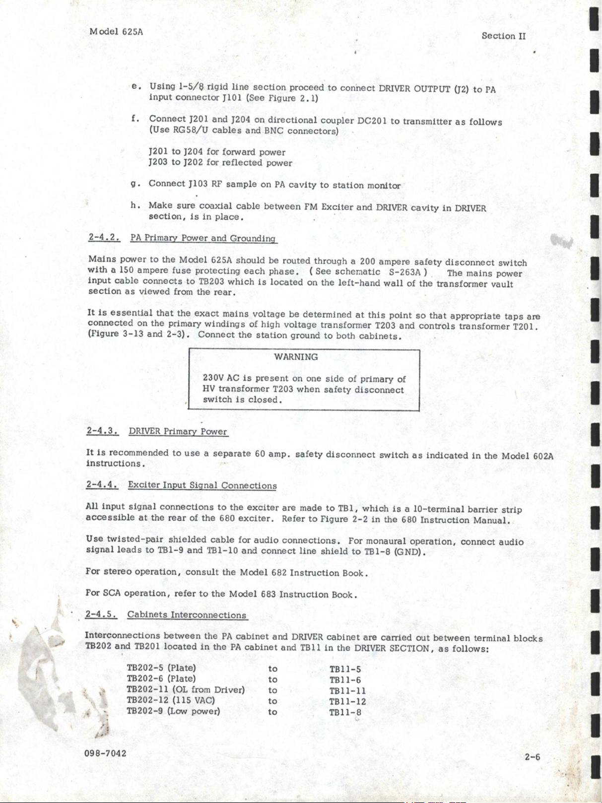
e.
Using
1-5/e
rigid
line
section
proceed
to
connect
DRIVER
OUTPUT (J2)
to
PA
input
connector
Jl0l
(See
Figure
2
.1)
f.
Connect
J201
and
J204 on
directional
coupler
DC201
to
transmitter
as
follows
(Use
RG58/U
cables
and
BNC
connectors)
J201
to
J204 for
!orward
power
J203
to
J202
for
reflected
power
g.
Connect
Jl03
RF
sample
on
PA
cavity
to
station
monitor
h.
Make
sure
coaxial
cable
between
FM
Exciter
and
DRIVER
cavity
in
DRIVER
section,
is
in
place.
2-4.
2.
PA
Primary
Power
and
Grounding
Mains
power
to
the
Model
625A
should
be routed
through
a 200
ampere
safety
disconnect
switch
with
a 150
ampere
fuse
protecting
each
phase.
(
See
scher:iatic
S-263A ) . The
mains
power
input
cable
connects
to
TB203
which
is
located
on
the
left-hand
wall
of
the
transformer
vault
section
as
viewed
from
the
rear.
It
is
essential
that
the
exact
mains
voltage
be
determined
at
this
point
so
that
appropriate
taps
are
connected
on
the
primary
windings
of
high
voltage
transformer
T203
and
controls
transformer
T201.
(Figure
3-13
and
2-3).
Connect
the
station
ground
to
both
cabinets.
WARNING
230V
AC
is
present
on
one
side
of
primary
of
HV
transformer
T203
when
safety
disconnect
switch
is
closed.
2-4.
3.
DRIVER
Primary
Power
It
is
recommended
to
use
a
separate
60
amp.
safety
disconnect
switch
as
indicated
in
the
Model
602A
instructions.
2-4.
4.
Exciter
Input
Signal
Connections
All
input
signal
connections
to
the
exciter
are
made
to
TBl,
which
is
a
IO-terminal
barrier
strip
accessible
at
the
rear
of
the
680
exciter.
Refer
to
Figure
2-2
in
the
680
Instruction
Manual.
Use
twisted-pair
shielded
cable
for
audio
connections.
For
monaural
operation,
connect
audio
signal
leads
to
TBl-9
and
TBl-10
and
connect
line
shield
to
TBl-8
(GND).
For
stereo
operation,
consult
the
Model
682
Instruction
Book.
For
SCA
operation,
refer
to
the
Model
683
Instruction
Book.
2-4.
5.
Cabinets
Interconnections
Interconnections
between
the
PA
cabinet
and
DRIVER
cabinet
are
carried
out
between
terminal
blocks
TB202
and
TB201
located
in
the
PA
cabinet
and
TBll
in
the
DRIVER
SECTION,
as
follows:
098-7042
TB202-5 (Plate)
TB202-6 (Plate)
TB202-ll
(OL from Driver)
TB202-12 (115
VAC)
TB202-9 (Low power)
to
to
to
to
to
TBll-5
TBll-6
TBll-11
TBll-12
TBll-8
2-6
I
I
I
I
I
I
I
I
I
I
I
I
I
I
I
I
I
www.SteamPoweredRadio.Com
I
I
I
I
I
I.
I
I
I
I
I
I
I
I
I
I
I
I
I
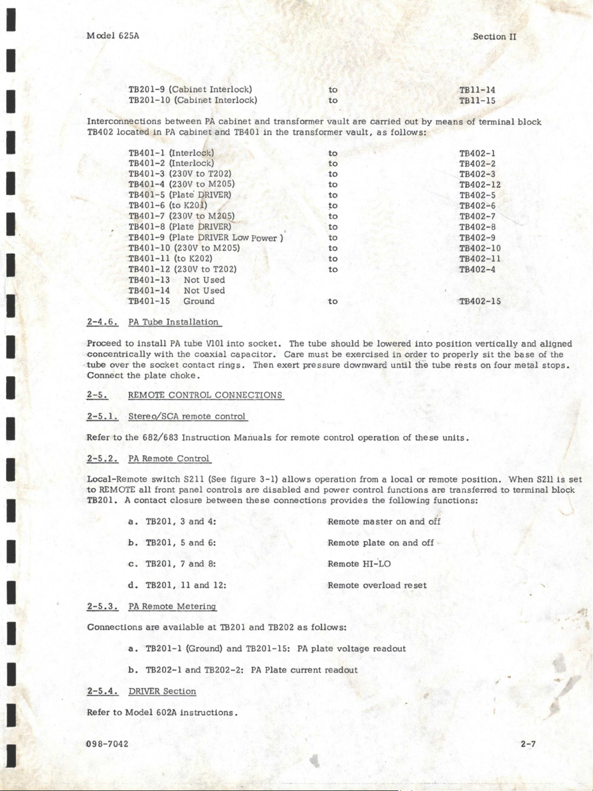
Model
625A
TB201-9
(
Cabin
et
Interlock)
TB201-10
(Cabinet
Interlock)
to
to
_
section
II
TBll-14
TBll-15
Interconnections
between
PA
cabinet
and
transformer
vault
are
carried
out
by
means
of
terminal
block
TB402
located
in
PA
cabinet
and
TB401
in
the
transformer
vault,
as
follows:
TB401-l
(Interlock)
to
TB402-l
TB401-2
(Interlock)
to
TB402-2
TB401-3
(230V
to
T202)
to
TB402-3
TB401-4
(230V
to
M205)
to
TB402-12
TB401-5
(Plate
DRIVER)
to
TB402-5
TB401-6
(to K201)
~o
TB402-6
TB401-7 (230V
to
M205)
to
TB402-7
TB401-8
(Plate
DRIVER)
·
to
TB402-8
TB401-9
(Plate
DRIVER
Low
Power)
to
TB402-9
TB401-10
(230V
to
M205)
to
TB402-10
'TB401-ll
(to K202)
to
TB402-ll
TB401-12
(230V
to
T202)
to
TB402-4
TB401-13
Not
Used
'
TB401-14
Not
Used
_TB401-15
Ground
to
·
TB402-15
2-4.6.
PA
Tube
Installation
Proceed
to
install
PA
tube
VlOl
into
socket.
The
tube
should
be
lowered
into
position
vertically
and
aligned
concentrically
with
the
coaxial
capacitor.
Care
must
be
exercised
in
order
to
properly
sit
the
base
of
the
tube
over
the
socket
contact
rings.
Then
exert
pre
s
sure
downward
until
the
tube
rests
on
four
metal
stops.
Connect
the
plate
choke.
2-5.
REMOTE CONTROL CONNECTIONS
2-5
.1.
Stereo/SCA
remote
control
Refer
to
the
682/683
Instruction
Manuals
for
remote
control
operation
of
these
units.
-2-5.
2.
PA
Remote
Control
Local-Remote
switch
S211 (See
figure
3-1)
allows
operation
from a
local
or
remote
position.
When
S211
is
set
to
REMOTE
all
front
panel
controls
are
disabled
and
power
control
functions
are
transferred
to
terminal
block
TB201. A
contact
closure
between
these
connections
provides
the
following
functions:
a.
TB201, 3
and
4:
Remote
master
on
and
off
b.
TB201, 5
and
6:
Remote
plate
on
and
off
c.
TB201, 7
and
8:
Remote
HI-
LO
d.
TB201,
11
and
12:
Remote
overload
reset
2-5.3.
PA
Remote
Metering
Connections
are
available
at
TB201
and
TB202
as
follows:
2-5.4.
a.
TB201-l
(Ground)
and
TB201-15:
PA
plate
voltage
readout
b.
TB202-l
and
TB202-2:
PA
Plate
current
readout
DRIVER
Section
Refer
to
Model
602A
instructions.
098-7042
2-7
www.SteamPoweredRadio.Com
I
I
I
I
I
I.
I
I
I
I
I
I
I
I
I
I
I
I
I
Model
625A .
SECTION
Ill
OPERATION
3-1.
PA
CONTROLS
AND
INDICATORS
Section
III
As
shown
in
figures
3-1
and
3-2,
all
operational
controls
and
indicators
are
located
at
the
front
of
the
unit.
Table
3-1
lists
these
operating
controls
and
indicators
and
gives
their
reference
designation
and
a
brief
functional
description
of
each.
3-1.1.
DRIVER
Section
For
controls
and
indicators
located
in
the
DRIVER
section,
refer
to
Model
625A
Instruction
Book.
098-7042

www.SteamPoweredRadio.Com
Section
III
ICJ
0
~26
3-2
CJ
CJ
CJj
000
0
FINAL
0
TUI/IN(,
Dl!VR
TUNING
0 0 0
0
0
0 0
S3 SB
la
. .
0 0 0
o.
SI
SIO
ss
Sf
MODEL
680
FM
EXCITER
MODEL
682.
STE~Eo
GEN.
~EL
683
~CA
C:,EIJ
,
.
0 0 0 0
□
C8/
DRIVER
SECTION
SEE
MODEL
60
2 A
1WSTRVCTION
800K
-DSZCG
~-
OSZ0
3
-oszos
I
!MZMI
!mo2j
-
(,(
0
!1112031
!M
20
6I
I
LIDS
",
I
......
L/04
~
I
OUTPc/T
q
lOADJNC,
OVTPfJT
TUNING
I C/02.
"IJJPr/T
TUNIN(r
()
·i
~
-
~~~
N
l'\J
N
._.
''""
-~r3rj--~~~
µjzos!
o o o !
11M.?•1!
o o o !
Mzo,
!
s?H(~,~
(~.j
$1.,
<:)~
......
~
~
'
....
Q
0
"'"'
N
NN
N
").,
..,
..,
V)
II)
-
0 0 0
0
Ff
'2
F3
Ff.
D
CBI
POWER
t4MPI.IFIEJ€ Sl:CTIOI/
Front
View -
Component
Location
Figure
3-1
Model
625A
R22/
A.PJl/ST
MZ06
FOR.
100
"/,
CAL.
'
PLATE
!mf
CBZ.
#lbll
VOL
7A4E
.POWGR
.SUPPi.'/'
,5/ie.TION
·
098-7042
•
•
•
I
I
I
I
I
I
I
I
I
I
I
I
I
I
I
I
I
I
I

www.SteamPoweredRadio.Com
I
I
I
I
I
I
I
I
I
I
I
I
I
I
I
I
I
I
I
Mcxiel
625A
Ref.
Des.
DS202
DS203
DS205
M204
M203
M202
M206
Ll04
Ll05
Cl02
M205
HM201
M201
T201
-
098-7042
Section
III
:fable
3-1.
Operating
Controls
and
Indicators
PA
Section
Panel
Nomenclature
Function
PA
METER
PANEL
(Fi
gure
3-1)
FIL
INTERLOCKS
PLATE
PA
GRID CURRENT
PA
PLATE
CURRENT
PA
PLATE
VOLTAGE
PA
POWER
OUT
I
Indicates
power
applied
to
filament
contactor
K204
and
consequently
to
PA
Filament
when
lit.
Indicates
time
delay
complete
·
and
PA
cabinet
interlock
switches
closed
when
lit.
Indicates
Plate
Voltage
applied
to
Vl0l
when
lit.
Provides
continuous
readout
of
PA
grid
current.
Provides
continuous
readout
of
PA
plate
current.
Provides
continuous
readout
of
PA
plate
voltage.
As
selected
by
PA
POWER OUT
switch
S213
provides
readouts
of
PA
forward
and
reflected
RF
power
output.
(VSWR).
(See
section
4-6.2.)
PA
CAVITY
FRONT
PANEL
(FIGURE
3-1)
'
.,
1
OUTPUT
TUI'JIING
• i
I
OUTPUT LOADING
INPUT TUNING
Tunes
Vl0l
plate
to
resonance.
Adjust
Vl0
1
plate
loading.
Tunes
the
input
circuit
of
Vl0l
to
resonance.
PA
CONTROL
PANEL
(FIGURE
l-1)
AC
LINE
VO
LTAGE
HOURS
PA
FILAMENT
VOLTAGE
PA
FILAMENT ADJUSTMENT
As
selected
by
AC
Line
Voltage
switch
S214,
provides
readouts
of
phase
to
phase
AC
line
voltage.
Provides
cumulative
transmitter
operating
time.
Provides
continuous
readout
of
PA
filament
voltage.
Adjust
PA
filament
voltage
as
monitored
by
M201.
Popular Transmitter manuals by other brands


Greystone Energy Systems
Greystone Energy Systems HATDFL Series installation instructions

NEUTRIK
NEUTRIK xirium pro user manual

Nautel
Nautel VS300 quick start guide

Allstar
Allstar CKT-240 installation instructions

Magnetrol
Magnetrol PULSAR RADAR R86 Functional safety manual

Micron
Micron POCKET TRANSMITTER TX716A Quick user guide