D2657-01-01
4.2~ELECTRICAL (continued)
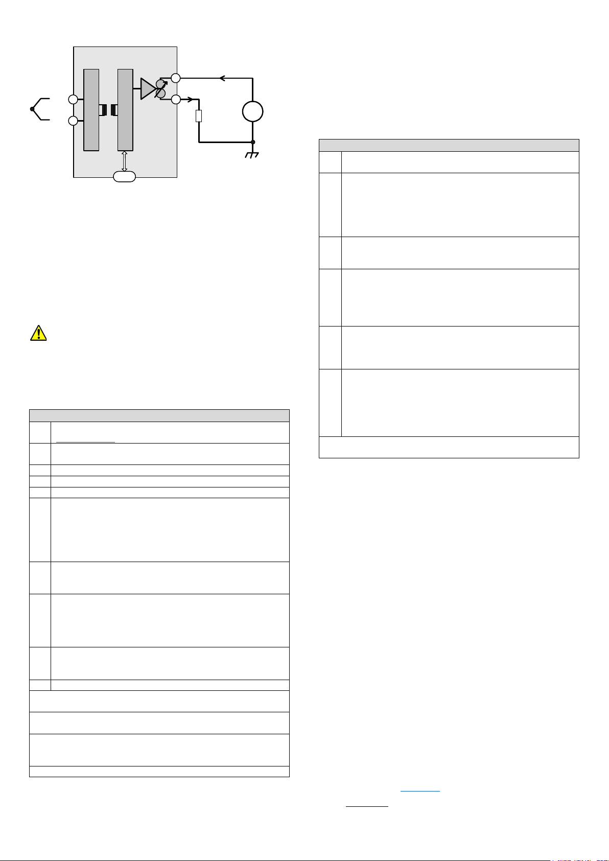
SEM1605TC Basic block diagram.
-
2 Wire (4 to 20) mA
Output
+
-
Vs
Loop
Load
+
-
+
U SB
It is good practice to ensure that the (4 to 20) mA loop is grounded at
a single point in the loop.
Before installation, care must be taken to ensure enough voltage is
available in the loop to drive the total loop load.
4.3~S LED (STATE)
The State LED is off under normal run conditions indicating an in-
range input signal. If the input signal is out of range or is lost, the
State LED will light (RED)
The State LED also has some programming functions. See 5.2
5~USER CONFIGURATION.
The SEM1605TC can be configured whilst connected and
powered, but a portable battery powered computer or USB isolator
must be used to avoid the effects of ground loops.
Observe any warning information given in the software.
5.1~PC CONFIGURATION USBSpeedLink Software
Download and install the USBSpeedLink software from
www.status.co.uk
Run the software and open to the correct screen for the
SEM1605TC
Connect to the PC using an A to Mini B USB lead.*1
Read the current configuration into the software.
Configure the device to the required settings for operation.
Standard configuration options.
TC Sensor type
Offset
Low and High range
Error signal value
Active configuration options.
4 mA or 20 mA: On click of the button the signal on the input will be
entered for Low (4 mA) or High (20 mA) range value.
*2
Diagnostic configuration options.
Pre-set Temperature: This will fix the input value to the device at the
entered value.*4
Pre-set Loop Current: This will fix the mA output value from the
device to the entered value.
*4
Read data: Live data can be displayed showing input and output
values. This can only be done if the device is powered as well as
connected to the software via the USB lead.
*3
Write/Save the configuration to the device. *2
*1 Once only, on the first time connecting to the SEM1605TC, drivers will
install to the PC, allow time for this before proceeding.
*2 The configuration is not saved onto the device unless the configuration
screen is sent.
*3 The SEM1605TC can be configured whilst connected and powered, but
a portable battery powered computer or USB isolator must be used to
avoid the effects of ground loops.
*4This will only clear when removed using the software.
5.2~BUTTON CONFIGURATION
Range configuration is available, sensor type must be set using the
configuration software.
A thermocouple simulator and connecting cable of the correct type of
sensor selected in the software will be required.
Alternatively, a thermocouple sensor can be connected if means of
controlling its temperature at the required temperature values is
available, for example a hot block.
Buttons: Active Range Configuration steps
User-range function allows manual adjustment of the 4 mA and 20
mA output range in relation to the input value.
Connect a resistor decade box or an input sensor to the
SEM160TC using the two connection terminals. Connect the
SEM1605TC to a (10 to 30) VDC power supply. A digital ammeter
connected in series with the SEM1605TC will be useful to monitor
the (4 to 20) mA current but is not essential.
Turn on the supply and allow 1-minute warm up period.
Set the thermocouple simulator to the required low range
temperature or apply required low range temperature to the sensor.
Allow 10 seconds for the SEM1605TC to settle.
Press and hold the Low range button until the S LED starts to
flash, then release the button.
Press and release the Low range button again, the S LED will
flash quickly for a short time and the new low range will be stored.
The output current will go to 4.00 mA.
Set the thermocouple simulator to the equivalent required high
range temperature or apply required high range temperature to the
sensor.
Allow 10 seconds for the SEM1605TC to settle.
Press and hold the High range button until the S LED starts to
flash, then release the button.
Press and release the High range button again, the S LED will
flash quickly for a short time and the new high range will be stored.
The output current will go to 20.00 mA.
The ranging of the SEM1605TC is now complete.
Note:- The Low and High user-adjust can be set individually and in any
order, as required.
5.3~ANDROID MONITORING USBViewLink Software
Using a suitable OTG USB lead to connect the SEM1605TC to an
Android device, live data reading can be taken.
The USBViewLink app. can display input temperature, output mA and
the Tag information.
This guide is also available online at www.status.co.uk
Status Instruments Ltd, Status Business Park, Gannaway Lane, Tewkesbury, Gloucestershire, UK, GL20 8FD,
Web Page: www.status.co.uk,
Technical Support: support@status.co.uk
Tel: +44 (0) 1684 296818, Fax: +44 (0) 1684 293746


