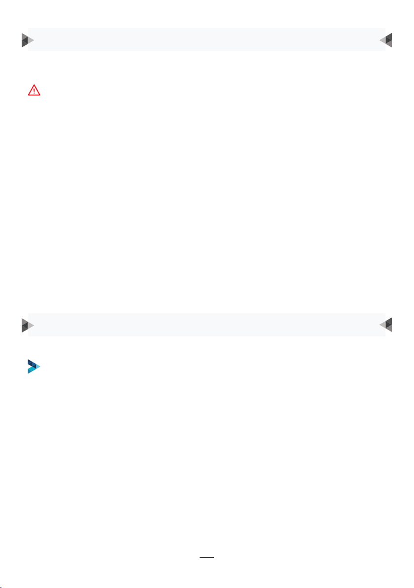
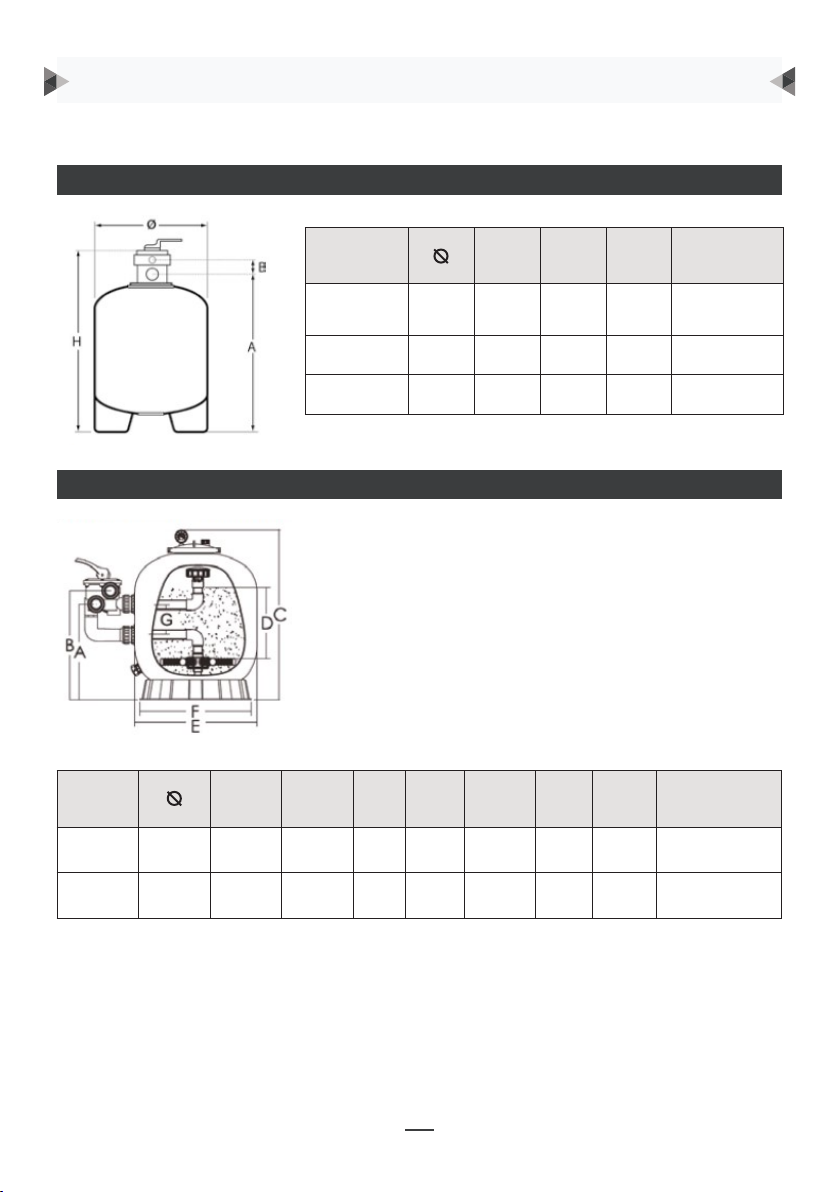
CF GROUP VITALIA XEOT05 User manual

EN DE ES IT
FR NL PT SE
INSTALLATION/SERVICING/MAINTENANCE/SAFETY INSTRUCTIONS - INSTALLATION / ENTRETIEN / MAINTENANCE / CONSEILS DE SÉCURITÉ - INSTALLATION / WARTUNG
/ INSTANDHALTUNG / SICHERHEITSHINWEISE - INSTALLATIE / VERZORGING / ONDERHOUD / VEILIGHEIDSADVIES - INSTALACIÓN / CONSERVACIÓN / MANTENIMIENTO
/ RECOMENDACIONES DE SEGURIDAD - INSTALAÇÃO / CUIDADOS A TER / MANUTENÇÃO / CONSELHOS DE SEGURANÇA - INSTALLAZIONE / CURA / MANUTENZIONE /
CONSIGLI DI SICUREZZA - INSTALLATION / SKÖTSEL / UNDERHÅLL / SÄKERHETSANVISNINGAR - INSTALACE / PÉČE / ÚDRŽBA / BEZPEČNOSTNÍ DOPORUČENÍ
INSTALLATION INSTRUCTIONS / NOTICE D’INSTALLATION /
INSTALLATIONSANLEITUNG / INSTALLATIE INSTRUCTIES / MANUAL
DE INSTALACIÓN / MANUAL DE INSTALAÇÃO / ISTRUZIONI PER
L’INSTALLAZIONE / INSTALLATIONSINSTRUKTIONER /
INSTALAČNÍ POKYNY
CS
FILTRATION / FILTRATION / FILTRATION / FILTRATIE / FILTRACIÓN / FILTRAÇÃO
/ FILTRAZIONE / FILTRERING / FILTRACE
VITALIA TOP/SIDE SAND FILTER - FILTRE À SABLE VITALIA TOP / SIDE
- SANDFILTER VITALIA TOP / SIDE - ZANDFILTER VITALIA TOP / SIDE -
FILTRO DE ARENA VITALIA TOP / SIDE - FILTRO A SAL VITALIA TOP / SIDE -
FILTRO A SABBIA VITALIA TOP / SIDE - VITALIA TOP / SIDE SANDFILTER -
PÍSKOVÝ FILTR VITALIA TOP / SIDE

EN...............................................................................................................................................2
FR .............................................................................................................................................10
DE.............................................................................................................................................18
NL .............................................................................................................................................26
ES ............................................................................................................................................ 34
PT ............................................................................................................................................ 42
IT ............................................................................................................................................. 50
SE ............................................................................................................................................ 58
CS.............................................................................................................................................66

2
PLEASE READ THESE INSTRUCTIONS CAREFULLY AND KEEP THEM FOR FUTURE REFERENCE
The aim of this CF GROUP sand filter instruction manual is to provide you with all the
information you need for optimal installation, use and maintenance. It is essential to read
this document carefully and to keep it in a safe place for future reference.
Wear proper safety equipment (safety shoes, goggles, mask, gloves, appropriate clothing)
when installing the equipment!
Consult the instructions provided by the manufacturer(s) for power tools and products
used.
CONTENTS
SAFETY ADVICE ....................................................................................................................... 3
LIST OF EQUIPMENT DELIVERED ............................................................................................ 3
INSTALLATION.......................................................................................................................... 4
Vitalia top sand filter.......................................................................................................... 4
Vitalia side sand filter ........................................................................................................ 4
Location............................................................................................................................... 5
Installation .......................................................................................................................... 5
Start-up............................................................................................................................... 7
Functions of valve positions .............................................................................................. 8
WARRANTY .............................................................................................................................. 9

3
SAFETY ADVICE
LIST OF EQUIPMENT DELIVERED
• A Vitalia TOP or SIDE sand filter
• A full Side valve kit 1”1/2
• Installation and use instructions
THE PACKAGE MUST INCLUDE:
• This filter operates under high pressure. When a component in the filter cicuit (pump,
filter, valve, etc.) is disassembled for maintenance purposes, air may enter the filter and
can be pressurised. The pressurised air may blow out the filter cover and cause serious
injury or even death, or material damage.
• Switch the pump o prior to opening the filter.
• In order to avoid the pump sustaining damage and to ensure that the system operates
correctly, clean the prefilter and the skimmers regularly.
• When the temperature is low, we strongly recommend using the winter setting and
emptying all of the water contained in the filter out of the drain at the bottom.
• This equipment is not intended for use by people (particularly children) whose physical,
sensorial or intellectual capacities are in any way reduced or by people who lack
experience or knowledge, unless they are under the supervision of or have received
instructions regarding use of the appliance from a person who is responsible for their
safety.
• Ensure that children cannot play with the equipment.
THE FILTER OPERATES UNDER PRESSURE, DO NOT UNSCREW THE FACEPLATE OF THE
COVER WHILE FILTRATION IS UNDERWAY.

4
INSTALLATION
VITALIA TOP SAND FILTER
VITALIA SIDE SAND FILTER
Model A B H Valve
connection
XEOT05 365 597 60 714,5 1”1/2
XEOT10 515 757 60 874,5 1”1/2
XEOT14 615 875 60 974,5 1”1/2
Model A B C D E F G Valve
connection
XEOS11 500 390 450 770 235 527 500 125 1”1/2
XEOS15 650 430 490 850 300 627 500 125 1”1/2

5
INSTALLATION
LOCATION
INSTALLATION
Install the filter on a flat and clean surface, making sure that there is easy access for
moving the valve, as well as for maintenance procedures.
PVC glue for the plastic pipe adaptors is required for installation of the filter.
The pump must be located below the water level of the pool. If this is not the case, ask
for advice from your installer.
Ensure that the 8 strainers are correctly clipped into their slots on the collector.
• Temporarily block the top part of the distributor tube in order to avoid filling it with
sand.
• Putting in the sand:
-Fill the tank 1/3 full of water in order to protect the strainers when the sand is put in.
-Make sure that the centre pipe is correctly centred in relation to the top hole.
-Pour in the sand slowly to avoid knocking the centre tube o centre.
-Check that the centre tube is in the right position.
-Pour in the remaining sand (See Technical information).
N.B: If you are using sand with dierent grain textures, make sure that the sand with
the largest grains is placed at the bottom of the tank.
-Unblock the centre pipe.
• Installing the valve:
-Using a Teflon, place the pressure gauge on the valve in place of the plastic screw.
-Place the O-ring on the Top joint.
-Clean the top face plate of the filter.
-Position the valve, checking that the “PUMP” channel is directed towards the pump.
-Place the two semi-flanges on either side of the valve, making sure that you place
the “screw imprints” on the opposite side. Make sure that you insert the face plates of
the valve into the flange correctly.
-Insert the screws and nuts as per the diagram and tighten the flange using a cross-
headed screwdriver. Screw the two screws in bit by bit alternately to ensure that they
are tightened evenly.
-Your valve is now solidly installed with the tank and is sure to be watertight.
• Connect the valve to the filter pump, to the drain and to the pool discharge.
TOP VERSION

6
INSTALLATION
Ensure that the 8 strainers are correctly clipped into their slots on the collector.
• Setting up the Side valve:
-Using a Teflon, place the pressure gauge on the valve in place of the plastic screw.
-Insert the plastic screws into the connections.
-Using a Teflon, screw the connectors onto the valve.
-Straight connection to the “Top” inlet of the Valve.
-Elbow connection to the threading located below the Valve.
-Place the O-rings in the tumbler of the wall conduits.
-Attach the valve to the tank by screwing in the screws on the wall conduits.
• Putting in the sand:
- Fill the tank 1/3 full of water in order to protect the strainers when the sand is put in.
- Pour in the first bag of sand slowly.
- Pour in the rest of the sand (See Technical information)
Check that the centre tube is in the right position. N.B: If you are using sand with
dierent grain textures, make sure that the sand with the largest grains is placed at
the bottom of the tank.
• Remove the plug.
• Screw the “diuser” part onto the top conduit.
• Installing the dome.
-Place the O-ring on the dome.
-Clean the top face plate of the filter to avoid having any sand under the joint.
-Place the two semi-flanges on either side of the dome, making sure that you place the
“screw imprints” on the opposite side. Make sure that you insert the face plates of the
dome into the flange correctly.
-Insert the screws and nuts as per the diagram and tighten the flange using a cross-
headed screwdriver. Screw the two screws in bit by bit alternately to ensure that
tightening is even.
• Connect the valve to the filter pump, to the drain and to the pool discharge.
SIDE VERSION

7
INSTALLATION
START-UP
1 • Make sure that you have put the correct amount of filtering sand into the filter and
that all of the connectors are in place and attached.
2 • Press the handle of the 6-way valve and turn it to the BACKWASH position. (In order
to prevent the joint of the 6-way valve from being damaged, always press the
handle before turning it.)
3 • Prime and start up the pump by following the pump instructions (check that all of
the suction and return pipes are open), by letting the filter fill with water. Once water
starts to come out of the drainage pipe, let the pump operate for at least 1 minute.
We recommend carrying out an initial wash to eliminate impurities or fine particles of
sand.
4 • Switch the pump o and set the valve to the RINSE position. Start up the pump and
leave it to operate until the water in the indicator is clear for at least ½ to 1 minute.
Switch the pump o, set the valve to the FILTER position and start up the pump
again. The filter will now be operating in normal filtration mode, and it will filter out
fine particles of dirt from the pool.
5 • Set the suction and return valves of the pool in order to obtain the required flow rate.
Check that the system and the filter are not leaking and tighten the connectors, the
nuts and screws as shown.
6 • Take note of the initial value displayed on the pressure gauge when the filter is
clean. (It will vary from one pool to another depending on the pump and the general
pipework system). As the filter removes dirt and impurities, there will be a build-up
that leads to increased pressure and reduces the water flow. When the pressure on
the gauge reaches 1.5 bar above the initial value (when the filter was “clean”), this
means that it is time to clean the filter (see the BACKWASH section below).
Note: When the water from a pool is first cleaned, it may be necessary to wash the
filter more frequently due to the initial amount of dirt in the water.

8
INSTALLATION
FUNCTIONS OF VALVE POSITIONS
Filtration
Wash
DRAINAGE
DRAINAGE
DRAINAGE
DRAINAGE
DRAINAGE
DRAINAGE
INLET
FLOW
INLET
FLOW
INLET
FLOW
INLET
FLOW
INLET
FLOW
INLET
FLOW
OUTLET
FLOW
OUTLET
FLOW
OUTLET
FLOW
OUTLET
FLOW
OUTLET
FLOW
OUTLET
FLOW
Emptying
Rinse
Close
Circulation
POSITION FUNCTION
Filtration Normal filtration
Wash Cleans the filter by reversing the flow
Rinse Allows dirt in the valve to be removed after washing
Empty Bypass position for the filter to empty out impurities or to
reduce the water level
Circulation Bypass position for the filter to circulate water into the pool
without going through the filter
Close Shuts o all flows towards the filter or the pool – do not
activate the pump!
FFUUNNCCTTIIOONNSS OOFF VVAALLVVEE PPOOSSIITTIIOONNSS
SSEERRVVIICCIINNGG VVAALLVVEE
Disassembly:
1. Turn off the pump and close the suction and discharge valves.
2. Place the multi-way valve in the FILTER position.
3. Remove the screws from the cover.
4. Remove the handle, cover and plug assembly.
Assembly:
1. Place the valve handle in the FILTER position.
2. Put the O-ring on the cover.
3. Position the handle, cover and plug assembly on the valve body according to the coding.
4. Tighten every other screw evenly on the cover. Do not overtighten.
WWAARRNNIINNGG
THIS FILTER OPERATES UNDER PRESSURE. DO NOT UNSCREW THE LID COLLAR WHEN FIL-
TRATION IS IN SERVICE.
TURN OFF THE PUMP BEFORE CHANGING THE POSITION OF THE MULTI-CHANNEL VALVE.
REGULARLY CLEAN THE PRE-FILTER OF THE PUMP.
IN LOW TEMPERATURE CONDITIONS, IT IS HIGHLY RECOMMENDED TO PUT THE MULTI-WAY
VALVE IN THE WINTER POSITION AND TO DRAIN THE WATER CONTAINED IN THE FILTER BY
BOTTOM DRAINING.

9
WARRANTY
• CF GROUP sand filters are guaranteed against all material and/or manufacturing
defects for a period of 2 years starting from the date of delivery.
• No warranty shall be valid if the equipment has not been paid for in full.
• No operations undertaken as part of the warranty shall have the eect of extending the
latter.
• Presentation of the purchasing invoice shall be systematically required for any claims
arising under the warranty.
• As part of this warranty, the only obligation incumbent upon CF GROUP shall be, subject
to the choice of CF GROUP, replacement or repair of the defective element free of
charge by CF GROUP’s services. The purchaser shall be responsible for any other fees.
• In order to benefit from this warranty, all products must first be submitted to CF GROUP’s
aftersales service, whose consent is essential for any replacement or repair process to
be authorised.
• The warranty shall not apply in case of visible defects. Defects and deteriorations
caused by normal wear and tear, defects arising from non-compliant assembly and/or
use, and any alterations to the product carried out without prior written consent from CF
GROUP shall also not be covered by the warranty.
Statutory warranty: Upon the condition that the purchaser has proven that there is
a latent defect, the seller is legally obliged to compensate for all the consequences
thereof (article 1641 et seq. of the French Civil Code). If the purchaser undertakes legal
action, they must do so within a short period of discovering the latent defect (article
1648 of the French Civil Code).

10
NOTICE À LIRE ATTENTIVEMENT ET À CONSERVER POUR UNE CONSULTATION ULTÉRIEURE
Le manuel des filtres à sable CF GROUP a pour but de vous donner toutes les informations
nécessaires à une installation, une utilisation et un entretien optimal. Il est indispensable
de se familiariser avec ce document et de le conserver dans un lieu sûr et connu pour des
consultations ultérieures.
Porter les équipements de sécurité (chaussures de sécurité, lunettes, masque, gants,
vêtements adaptés) adéquats lors de l’installation !
Se référer aux notices des matériels électroportatifs et produits utilisés fournies par le(s)
fabricant(s).
SOMMAIRE
CONSIGNES DE SÉCURITÉ..................................................................................................... 11
LISTE DU MATÉRIEL LIVRÉ ...................................................................................................... 11
INSTALLATION......................................................................................................................... 12
Filtre à sable vitalia top.................................................................................................... 12
Filtre à sable vitalia side................................................................................................... 12
Emplacement..................................................................................................................... 13
Installation ......................................................................................................................... 13
Mise en service................................................................................................................... 15
Fonctions des positions de la vanne ............................................................................... 16
GARANTIE................................................................................................................................ 17

11
CONSIGNES DE SÉCURITÉ
LISTE DU MATÉRIEL LIVRÉ
• Un filtre à sable Vitalia TOP ou SIDE
• Un kit vanne Side complet 1”1/2
• Une notice d’installation et d’utilisation
LE COLIS DOIT COMPORTER :
• Ce filtre fonctionne sous haute pression. Lorsqu’un composant du circuit de filtration
(pompe, filtre, vannes, etc.) est démonté pour l’entretien, l’air peut pénétrer dans le filtre
et être mis sous pression. L’air sous pression peut souer le couvercle du filtre et entrainer
des blessures graves, voire mortelles, ou des dommages matériels.
• Mettez la pompe hors tension avant d’ouvrir le filtre.
• Pour éviter que la pompe soit endommagée et pour que le système fonctionne correctement,
nettoyez régulièrement le préfiltre de la pompe et les skimmers.
• Dans des conditions de basse température, il est fortement recommandé de mettre en
position d’hiver et de vider toute l’eau contenue dans le filte à travers le drain de fond.
• Cet appareil n’est pas destiné à être utilisé par des personnes (notamment des enfants)
dont les capacités physiques, sensorielles ou intellectuelles sont réduites ou par des
personnes manquant d’expérience ou de connaissances, à moins que celles-ci fassent
l’objet d’une surveillance ou qu’elles aient reçu des instructions quant à l’utilisation de
l’appareil par une personne responsable de leur sécurité.
• Veillez à ce que les enfants ne puissent pas jouer avec l’appareil.
LE FILTRE FONCТIONNE SOUS PRESSION. NE PAS DEVISSER LA COLERETTE DU
COUVERCLE LORSQUE LA FILTRATION EST EN SERVICE.

12
INSTALLATION
FILTRE À SABLE VITALIA TOP
FILTRE À SABLE VITALIA SIDE
Modèle A B H Raccord
Vanne
XEOT05 365 597 60 714,5 1»1/2
XEOT10 515 757 60 874,5 1»1/2
XEOT14 615 875 60 974,5 1»1/2
Modèle A B C D E F G Raccord
Vanne
XEOS11 500 390 450 770 235 527 500 125 1»1/2
XEOS15 650 430 490 850 300 627 500 125 1»1/2

13
INSTALLATION
EMPLACEMENT
INSTALLATION
Installez le filtre sur une surface plane et propre tout en vous assurant un accès aisé
pour les manipulations de la vanne, ainsi que pour les diérentes interventions de
maintenance.
La colle PVC des tuyaux pour les adaptateurs en plastique est requise pour l’installation
du filtre.
La pompe doit être en charge, c’est à dire en-dessous du niveau d’eau de la piscine .
Dans le cas contraire, demander conseil à votre installateur.
Assurez-vous que les 8 crépines sont sont correctement clipsées dans leur logement du
collecteur.
• Obturez temporairement la partie supérieure du tube répartiteur afin de ne pas le
remplir avec le sable.
• Mise en place du sable :
- Remplissez la cuve au 1/3 avec de l’eau afin de protéger les crépines lors de la chute
du sable.
- Assurez-vous que le tuyau central est bien dans l’axe par rapport à l’orifice supérieur.
- Versez délicatement le premier sac de sable afin de ne pas désaxer le tuyau central.
- Vérifiez la bonne position du tuyau central.
- Versez la quantité de sable restante ( Cf : Informations techniques).
N.B : Si vous utilisez du sable de granulométries diérentes, disposez le plus gros en
fond de cuve.
- Débouchez le tuyau central.
• Mise en place de la vanne :
- Disposez, à l’aide de téflon, le manomètre sur la vanne à la place de la vis plastique.
- Placez le joint torique sous la vanne Top.
- Nettoyez la collerette supérieure du filtre.
- Positionnez la vanne en contrôlant que la voie « PUMP » est dirigée vers la pompe.
- Disposez les deux demi-brides de part et d’autre de la vanne en prenant soin de
placer les « empreintes écrou » à l’opposé. Veillez à bien insérer les collerettes de la
vanne et du filtre dans la bride.
- Insérez vis et écrous selon le schéma et serrez la bride à l’aide d’un tournevis cruciforme.
Alternez le vissage sur les deux vis afin d’avoir un couple de serrage homogène.
- Votre vanne est maintenant solidaire de la cuve et l’étanchéité est assurée.
• Connectez la vanne à la pompe de filtration, à l’égout et au refoulement piscine.
VERSION TOP

14
INSTALLATION
Assurez-vous que les 8 crépines sont correctement clipsées dans leur logements du
collecteur.
• Mise en place de la vanne Side :
- Disposez, à l’aide de téflon, le manomètre à la place de la vis plastique.
- Insérez les écrous plastiques sur les raccords.
- Vissez les raccords sur la vanne à l’aide de Téflon.
- Raccord droit sur la l’entrée « Top » de la Vanne.
- Raccord coudé sur le taraudage situé sous la Vanne.
- Positionnez les joints toriques dans la gorge des traverses de paroi.
- Fixez la vanne sur la cuve en vissant les écrous sur les traverses de paroi.
• Mise en place du sable :
- Remplissez la cuve au 1/3 avec de l’eau afin de protéger les crépines lors de la chute
du sable.
- Verser délicatement le premier sac de sable.
- Verser la quantité de sable restante ( Cf : Informations techniques)
N.B : Si vous utilisez du sable de granulométries diérentes, disposer le plus gros en
fond de cuve.
• Enlever le bouchon obturateur.
• Vissez la partie « diuseur » sur la conduite supérieure.
• Mise en place du dôme.
- Placez le joint torique sous le dôme.
- Nettoyez la collerette supérieure du filtre afin d’éviter la présence de sable sous le joint.
- Disposez les deux demi-brides de part et d’autre du dôme en prenant soin de placer
les « empreintes écrou » à l’opposé. Veillez à bien insérer les collerettes du dôme et du
filtre dans la bride.
- Insérez vis et écrous selon le schéma et serrez la bride à l’aide d’un tournevis
cruciforme. Alternez le vissage sur les deux vis afin d’avoir un couple de serrage
homogène.
• Connectez la vanne à la pompe de filtration, à l’égout et au refoulement piscine.
VERSION SIDE

15
INSTALLATION
MISE EN SERVICE
1 • Assurez-vous que la quantité correcte de sable de filtration se trouve dans le filtre et
que tous les raccordsbsonr en place et fixes.
2 • Appuyez sur la poignée de la vanne de 6 voies et faites-la tourner sur la position
BACKWASH (LAVAGE). (Pour empêcher que le joint de la vanne de 6 voies soit
endommagé, appuyez toujours sur la poignée avant de la tourner.)
3 • Amorcez et démarrez la pompe en vous reportant aux instructions de la pompe
(veillez à ce que toutes les conduites d’aspiration et de retour soient ouverte), en
laissant le filtre se remplir d’eau. Une fois que l’eau sort de la conduite d’évacuation,
faites fonctionner la pompependant au moins 1 minute. Un lavage initial est
recommandé pour éliminer les impuretés ou les particules de sables fines du sable.
4 • Mettez la pompe hors tension et régler la vanne sur la position RINSE (RINÇAGE).
Démarrez la pompe et faites-la fonctionner jusqu’à ce que l’eau dans le temoin
transparentsoit claire, pendant environ 1/2 à 1 minute. Mettez la pompe hors tension
et réglez la vanne sur la position FILTER (FILTRATION) et redémarrez la pompe. Le filtre
fonctionne maintenant en mode filtrationnormale, et filtre les particules de saleté de
l’eau de la piscine.
5 • Réglez les vannes d’aspiration et de retour de la piscineafin d’obtenir le flux souhaite.
Vérifiez que le système et le filtre ne fuient pas et serrez les raccords, les boulons et
les vis, comme indiqué.
6 • Notez la valeur initiale achée sur le manomètre lorsque le filtre est propre. (Elle
varie d’une piscine à l’autre en fonction de la pompe et du système de canalisation
général). Comme le filtre élimine les saletés et les impuretés de l’eau de la piscine,
l’accumulation de saletés dans le filtre entraine une augmentation de la pression et
réduit le flux d’eau. Lorsque le manomètre indique 1,5 bar au-dessus de la pression
initiale (lorsque le filtre était «propre»), il est temps de laver le filtre (reportez-vous à la
section BACKWASH (LAVAGE) ci-après).
Remarque : Lors du nettoyage initial de l’eau de la piscine, un lavage fréquent peut
être nécessaire en raison de la quantité initiale de saletés accumulées dans l’eau.

16
INSTALLATION
FONCTIONS DES POSITIONS DE LA VANNE
Filtration
Lavage
EVACUATION
EVACUATION
EVACUATION
EVACUATION
EVACUATION
EVACUATION
FLUX
D’ENTRÉE
FLUX
D’ENTRÉE
FLUX
D’ENTRÉE
FLUX
D’ENTRÉE
FLUX
D’ENTRÉE
FLUX
D’ENTRÉE
FLUX DE
SORTIE
FLUX DE
SORTIE
FLUX DE
SORTIE
FLUX DE
SORTIE
FLUX DE
SORTIE
FLUX DE
SORTIE
Vidange
Rinçage
Ferme
Circulation
POSITION FONCTION
Filtration Filtration normale
Lavage Nettoyage du filtre en inversant le flux
Rinçage Permet d’évacuer les saletés de la vanne après le lavage
Vidage Position Bypass du filtre pour vidange des impuretés ou
réduire le niveau d’eau
Circulation Position Bypass du filtre pour faire circuler l’eau vers la pis-
cine sans passer par le filtre
Ferme Ferme tous les flux vers le filtre ou la piscine - ne pas ac-
tionner la pompe !
FFUUNNCCTTIIOONNSS OOFF VVAALLVVEE PPOOSSIITTIIOONNSS
SSEERRVVIICCIINNGG VVAALLVVEE
Disassembly:
1. Turn off the pump and close the suction and discharge valves.
2. Place the multi-way valve in the FILTER position.
3. Remove the screws from the cover.
4. Remove the handle, cover and plug assembly.
Assembly:
1. Place the valve handle in the FILTER position.
2. Put the O-ring on the cover.
3. Position the handle, cover and plug assembly on the valve body according to the coding.
4. Tighten every other screw evenly on the cover. Do not overtighten.
WWAARRNNIINNGG
THIS FILTER OPERATES UNDER PRESSURE. DO NOT UNSCREW THE LID COLLAR WHEN FIL-
TRATION IS IN SERVICE.
TURN OFF THE PUMP BEFORE CHANGING THE POSITION OF THE MULTI-CHANNEL VALVE.
REGULARLY CLEAN THE PRE-FILTER OF THE PUMP.
IN LOW TEMPERATURE CONDITIONS, IT IS HIGHLY RECOMMENDED TO PUT THE MULTI-WAY
VALVE IN THE WINTER POSITION AND TO DRAIN THE WATER CONTAINED IN THE FILTER BY
BOTTOM DRAINING.

17
GARANTIE
• Les filtres à sable CF GROUP sont garantis contre tout défaut de matière et/ou de
fabrication pendant une durée de 2 ans à compter de la date de livraison.
• Aucune garantie ne saurait être validée à défaut de règlement intégral.
• Les interventions au titre de la garantie ne sauraient avoir pour eet de prolonger la
durée de celle-ci.
• La présentation de la facture d’achat sera rigoureusement exigée lorsque la garantie
sera invoquée.
• Au titre de cette garantie, la seule obligation incombant à CF GROUP sera, au choix de
CF GROUP, le remplacement gratuit ou la réparation du produit ou de l’élément reconnu
défectueux par les services de CF GROUP. Tous les autres frais seront à la charge de
l’acheteur.
• Pour bénéficier de cette garantie, tout produit doit être soumis au préalable au service
après-vente de CF GROUP, dont l’accord est indispensable pour tout remplacement ou
toute réparation.
• La garantie ne joue pas en cas de vice apparent. Sont également exclus les défauts et
détériorations provoqués par l’usure normale, les défectuosités résultant d’un montage
et/ou d’un emploi non conformes, et les modifications du produit réalisées sans le
consentement écrit et préalable de CF GROUP.
Garantie légale : A la condition que l’acheteur fasse la preuve du vice caché, le vendeur
doit légalement en réparer toutes les conséquences (article 1641 et suivants du Code
civil). Si l’acheteur s’adresse aux tribunaux, il doit le faire dans un bref délai à compter
de la découverte du vice caché (article 1648 du Code civil).

18
DIE GEBRAUCHSANWEISUNG AUFMERKSAM LESEN UND FÜR SPÄTERES NACHSCHLAGEN
AUFBEWAHREN
Das Handbuch für die Sandfilter CF GROUP enthält alle Informationen, die Sie für eine
optimale Installation, Bedienung und Wartung benötigen. Es ist unerlässlich, dass Sie sich
mit diesem Dokument vertraut machen und es an einem sicheren und bekannten Ort für
späteres Nachschlagen aufbewahren.
TragenSiebeiderInstallationeineangemesseneSicherheitsausrüstung(Sicherheitsschuhe,
Schutzbrille, Mundschutz, Handschuhe, geeignete Kleidung)!
Beziehen Sie sich auf die vom Hersteller/von den Herstellern bereitgestellten Anleitungen
für die verwendeten Elektrowerkzeuge und Produkte.
INHALTSVERZEICHNIS
SICHERHEITSHINWEISE ......................................................................................................... 19
MATERIALLISTE ....................................................................................................................... 19
INSTALLATION........................................................................................................................ 20
Sandfilter Vitalia Top........................................................................................................ 20
Sandfilter Vitalia Side ...................................................................................................... 20
Standort.............................................................................................................................. 21
Installation ......................................................................................................................... 21
Inbetriebnahme................................................................................................................ 23
Funktionen Der Ventilpositionen..................................................................................... 24
GARANTIE............................................................................................................................... 25

19
SICHERHEITSHINWEISE
MATERIALLISTE
• Ein Sandfilter Vitalia TOP oder SIDE
• Ein komplettes Side-Ventil-Set 1,5“
• Eine Installations- und Gebrauchsanleitung
DAS PAKET MUSS FOLGENDES ENTHALTEN:
• Dieser Filter arbeitet unter hohem Druck. Wenn eine Komponente des Filterkreislaufs
(Pumpe, Filter, Ventile usw.) zu Wartungszwecken ausgebaut wird, kann Luft in den
Filter eindringen und unter Druck gesetzt werden. Unter Druck stehende Luft kann
die Filterabdeckung wegblasen und zu schweren bis tödlichen Verletzungen oder
Sachschäden führen.
• Schalten Sie die Pumpe aus, bevor Sie den Filter önen.
• Um Schäden an der Pumpe zu vermeiden und eine ordnungsgemäße Funktion des
Systems zu gewährleisten, sollten Sie den Vorfilter der Pumpe und die Skimmer regelmäßig
reinigen.
• Bei niedrigen Temperaturen ist es sehr empfehlenswert, auf Winterbetrieb zu stellen und
das gesamte Wasser im Filter durch den Bodenablauf abzulassen.
• Dieses Gerät ist nicht dafür bestimmt, von Personen (einschließlich Kindern) mit
eingeschränkten physischen, sensorischen oder geistigen Fähigkeiten oder von
Personen ohne Erfahrung oder Kenntnisse benutzt zu werden, es sei denn, sie werden
dabei beaufsichtigt oder haben im Vorfeld von einer für ihre Sicherheit verantwortlichen
Person Anweisungen zur Benutzung des Geräts erhalten.
• Bewahren Sie das Gerät außerhalb der Reichweite von Kindern auf.
DER FILTER FONCТIONIERT UNTER DRUCK. SCHRAUBEN SIE DEN DECKELFLANSCH
NICHT AB, WENN DIE FILTERANLAGE IN BETRIEB IST.
This manual suits for next models
4
Table of contents
Languages:
Popular Water Filtration System manuals by other brands

deconta
deconta C 25 L operating instructions

Pentair
Pentair Fleck 5800 XTR Installer manual

PREMIER TECH
PREMIER TECH Rewatec Ecoflo ST-500 owner's manual

Blue Wave
Blue Wave EASY CLEAN 100 instruction manual

amiad
amiad SAF X Series Installation, operation & maintenance instructions

Aqua PRO
Aqua PRO AP-600W-A5-GST2 manual