manuals.online logo
Brands
  1. Home
  2. •
  3. Brands
  4. •
  5. CFM
  6. •
  7. Fan
  8. •
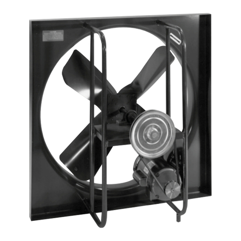
  9. CFM GEF10 Operating and safety instructions

CFM GEF10 Operating and safety instructions

SSEEFF,,PPEEFF&&GGEEFFEEXXHHAAUUSSTTFFAANNSSDDIIRREECCTTDDRRIIVVEE
RREEAADDAANNDDSSAAVVEETTHHEESSEEIINNSSTTRRUUCCTTIIOONNSSFFOORRFFUUTTUURREERREEFFEERREENNCCEE
AASSSSEEMMBBLLYYIINNSSTTRRUUCCTTIIOONNSS
MMOODDEELLSSSSEEFF--1100TTHHRROOUUGGHHSSEEFF--2244
CCoonntteennttss::Pre-assembled guard mount fan, shutter, shutter
mounting hardware kit, package of mounting screws.
To mount shutter to fan assembly:
1. Shutter mounting hardware kit includes: 4 rubber vibration
isolators, 4 nylon inserts, 4 screws (#12 x 1”) and 4 rubberized
washers.
2. Insert screws into washers - rubber side down.
3. Place nylon inserts into square holes of corner gussets at
rear of shutter.
4. Place shutter face down (gusset side up). Center vibration
isolators over nylon inserts.
5. Place fan assembly on shutter so that wire hooks on fan
guard are centered over vibration isolators and nylon
inserts. Junction box must be positioned at bottom with
shutter blades opening upwards.
6. Secure fan assembly to shutter using screws and washers.
7. Ensure that fasteners are snug. Do not over tighten to
avoid stripping nylon inserts.
MMOODDEELLSSEEFF--3300
CCoonntteennttss::Pre-assembled guard mount fan, shutter, shutter
mounting hardware kit, package of mounting screws.
To mount shutter to fan assembly:
1. Shutter mounting hardware kit includes: 4 rubber vibration
isolators, 8 rubber inserts, 8 screws (#8-32 x 11/2”) and 8
rubberized washers.
2. Insert screws into washers - rubber side down.
3. Place rubber inserts into round holes of corner gussets at
rear of shutter. It may be necessary to twist and push or tap
lightly to seat rubber inserts properly.
4. Place shutter face down (gusset side up). Center vibration
isolators over rubber inserts.
5. Place fan assembly on shutter so that wire hooks on fan
guard are centered over vibration isolators and nylon
inserts. Junction box must be positioned at bottom with
shutter blades opening upwards.
6. Secure fan assembly to shutter using screws and washers.
7. Ensure that fasteners are snug. Do not over tighten to
avoid pulling out rubber inserts.
MMOODDEELLSSPPEEFF--1
100TTHHRROOUUGGHHPPEEFF--3300
CCoonntteennttss::Pre-assembled panel mount fan.
MMOODDEELLSSGGEEFF--1100TTHHRROOUUGGHHGGEEFF--3300
CCoonntteennttss::Pre-assembled guard mount fan.
IINNSSTTAALLLLAATTIIOONN&&MMAAIINNTTEENNAANNCCEEGGUUIIDDEE
CCAAUUTTIIOONN!!TTHHEESSEEFFAANNSSAARREEDDEESSIIGGNNEEDDFFOORRGGEENNEERRAALL
VVEENNTTIILLAATTIIOONNUUSSEEOONNLLYY..DDOONNOOTTUUSSEETTOOEEXXHHAAUUSSTTCCOORRRROO--
SSIIV
VEE,,HHAAZZAARRDDOOUUSSOORREEXXPPLLOOSSIIVVEEMMAATTEERRIIAALLSSAANNDDVVAAPPOORRSS..
BBEEFFOORREEIINNSSTTAALLLLAATTIIOONN
WWAARRNNIINNGG!!TTOORREEDDUUCCEETTHHEERRIISSKKOOFFFFIIRREE,,EELLEECCTTRRIICCAALL
SSHHOOCCKK,,OORRIINNJJUURRYYTTOOPPEERRSSOONNSS,,PPLLEEAASSEEOOBBSSEERRVVEETTHHEE
FFOOLLL
LOOWWIINNGGSSAAFFEETTYYPPRREECCAAUUTTIIOONNSS::
1. TThhiissffaannhhaassrroottaattiinnggppaarrttss!!Turn impeller by hand to ensure
that it rotates freely.
2. Ensure that electrical service to fan is locked in the
“OOFFFF” position to prevent power from being switched on
accidentally. When the service disconnecting means
cannot be locked, securely fasten a prominent warning
device such as a tag to service panel.
3. Do not re-establish power supply until fan and activation
device are completely installed.
4. Installation work, including electrical wiring, must be
performed by a qualified person in accordance with all
applicable codes and standards, including local fire codes.
5. Check voltage at fan to see that it corresponds to fan motor
nameplate rating.
6. Fan is intended to be hard wired to a properly rated
electrical circuit, and must be properly grounded. Do
not use an extension cord.
7. Fan motor is equipped with thermal overload protection,
which causes fan to shut off automatically if motor overheats.
If this should happen, immediately disconnect and lock power
supply to fan. DDoonnoottaatttteemmppttttoowwoorrk
koonnffaannwwiitthhoouuttddiissccoonn--
nneeccttiinnggppoowweerrssuuppppllyy;;ffaannmmaayyrreessttaarrttwwiitthhoouuttwwaarrnniinngg!!
8. Fan should not be turned on and off rapidly.
9. Do not use fan with a solid state speed control device.
10. Do not allow fan to become wet or damp.
11. Do not block air intake or exhaust from fan.
12. Do not allow foreign objects to enter fan and come in
contact with fan blades.
SSPPEEEEDDSSEELLEECCTTOORRSSWWI
ITTCCHH
Fan is equipped with either a 2-speed or 3-speed pull chain switch,
allowing user to select desired airflow. Pulling a speed selector
switch repeatedly will cause fan speed to cycle as follows:
22--SSppeeeeddSSwwiittcchh::
OFF – FIRST SPEED – OFF – SECOND SPEED – OFF
33--SSppeeeeddSSwwiittcchh::
OFF – HIGH – MEDIUM – LOW – OFF
SSEEFFSSHHUUTTTTEERRMMOOUUNNTTFFAANNPPEEFFPPAANNEELLMMOOUUNNTTFFAANNGGEEFFGGUUAARRDDMMOOUUNNTTFFAANN
USA www.continentalfan.com Canada www.aeroflo.com
CCoonnttiinneennttaallFFaannMMaannuuffaaccttuurriinnggIInncc..
203 Eggert Rd.
Buffalo, NY 14215
Tel: 716-842-0670 Toll: 800-779-4021 Fax: 716-842-0611
AAeerrooffllooIInncc..
12-205 Matheson Blvd. East
Mississauga, ON L4Z 3E3
Tel: 905-890-6192 Toll: 800-779-4021 Fax: 905-890-6193
IINNSSTTAALLLLAATTIIOONNPPRROOCCEEDDUURREE
MMOODDEELLSSSSEEFF--1100TTHHRROOUUGGHHSSEEFF--3300
When shutter is mounted to fan assembly:
1. Cut square wall opening size ½” larger than fan blade
diameter.
2. From inside of building / room, center fan assembly over
wall opening. Fan must be positioned so that junction box
is located at bottom and shutter is level and square, with
shutter blades opening upwards.
3. Lag fan to wall through mounting holes in shutter gusset,
using appropriate fasteners (by others).
4. Rotate fan impeller by hand, ensuring that it is unobstructed
and rotates freely.
5. Make electrical connections to fan junction box.
When shutter and fan assembly are mounted separately:
1. Cut wall opening size ½” larger than fan blade diameter.
2. From inside of building / room, center fan assembly over
wall opening. Fan must be positioned so that junction box
is located at bottom.
3. Lag fan to wall through wire hooks on guard, using the
appropriate fasteners (by others).
4. Apply caulking compound (by others) to rear of shutter
gusset.
5. From outside of building / room, center shutter over wall
opening, ensuring that shutter is level and square, with
shutter blades opening upwards.
6. Lag shutter to wall through mounting holes in shutter gusset,
using appropriate fasteners (by others).
7. Rotate fan impeller by hand, ensuring that it is unobstructed
and rotates freely.
8. Make electrical connections to fan junction box.
MMOODDEELLPPEEFF--1100TTHHRROOUUGGHHPPEEFF--3300
1. Cut wall opening size ½” larger than fan venturi opening.
2. From inside of building / room, center fan panel assembly
over wall opening. Fan must be positioned so that
junction box is located at bottom.
3. Lag fan to wall through mounting holes in panel, using
appropriate fasteners (by others).
4. Rotate fan impeller by hand, ensuring that it is unobstructed
and rotates freely.
5. Make electrical connections to fan junction box.
MMOODDEELLSSGGE
EFF--1100TTHHRROOUUGGHHGGEEFF--3300
1. Cut wall opening size ½” larger than fan blade diameter.
2. From inside of building / room, center fan assembly over
wall opening. Fan must be positioned so that junction box
is located at bottom.
3. Lag fan to wall through wire hooks on fan guard, using the
appropriate fasteners (by others).
4. Rotate fan impeller by hand, ensuring that it is unobstructed
and rotates freely.
5. Make electrical connections to fan junction box.
RREECCOOMMMMEENNDDEEDDMMAAIINNTTEENNAANNCCEE
1. When undertaking maintenance or service work, ensure
that electrical service to fan is locked in the “OFF” position
to prevent power from being switched on accidentally.
When the service disconnecting means cannot be locked,
securely fasten a prominent warning device such as a tag
to service panel.
2. Do not re-establish power supply until maintenance or
service work has been completed.
3. Maintenance or service work must be performed by a qual-
ified person in accordance with all applicable codes and
standards, including local fire codes.
4. Motor bearings are factory lubricated and do not require
additional lubrication.
5. Remove airborne contaminants that have settled on motor
using an air hose or vacuum.
6. Clean fan blades, guard or shutter using a mild detergent.
Do not allow cleanser to come in contact with fan motor or
electrical parts.
LLIIMMIITTEEDDWWAARRRRAANNTTYY
This equipment is warranted to be free from defects in material
and workmanship for a period of one (1) year from date of
purchase. Any units or parts which prove to be defective
during warranty period will be repaired or replaced at
Vendor’s option. Vendor is not responsible for any removal,
installation or transportation costs.
Motors are warranted separately by motor manufacturer for
a period of one (1) year, and should be returned to nearest
authorized motor service center for repair.
All warranty claims must be processed through point of purchase.
WWIIRRIINNGGPPRROOCCEEDDUURREE
SEF-PEF-GEF I&M-0710

This manual suits for next models

7

Other CFM Fan manuals

CFM AXS100-EC Maintenance and service guide

CFM

CFM AXS100-EC Maintenance and service guide

CFM TF400 Maintenance and service guide

CFM

CFM TF400 Maintenance and service guide

CFM MFT-S Series Installation and operating instructions

CFM

CFM MFT-S Series Installation and operating instructions

CFM 165596 User manual

CFM

CFM 165596 User manual

CFM AIB-1006 User manual

CFM

CFM AIB-1006 User manual

CFM 165834 User manual

CFM

CFM 165834 User manual

CFM APK-0906 User manual

CFM

CFM APK-0906 User manual

CFM TBF90 Installation and operating instructions

CFM

CFM TBF90 Installation and operating instructions

CFM MNC-250 User manual

CFM

CFM MNC-250 User manual

CFM 167193 User manual

CFM

CFM 167193 User manual

CFM CF Maintenance and service guide

CFM

CFM CF Maintenance and service guide

CFM WEB-0807 User manual

CFM

CFM WEB-0807 User manual

CFM HRV-0904 User manual

CFM

CFM HRV-0904 User manual

CFM TBF120 Installation and operating instructions

CFM

CFM TBF120 Installation and operating instructions

CFM AFK-0906 User manual

CFM

CFM AFK-0906 User manual

CFM ADD-0911 User manual

CFM

CFM ADD-0911 User manual

CFM CDB-07 User manual

CFM

CFM CDB-07 User manual

CFM APW-0906 User manual

CFM

CFM APW-0906 User manual

CFM AeroFan User manual

CFM

CFM AeroFan User manual

CFM TF Series Maintenance and service guide

CFM

CFM TF Series Maintenance and service guide

CFM ECO-FLO Maintenance and service guide

CFM

CFM ECO-FLO Maintenance and service guide

CFM TF140-EC Maintenance and service guide

CFM

CFM TF140-EC Maintenance and service guide

CFM AXP100 Maintenance and service guide

CFM

CFM AXP100 Maintenance and service guide

CFM AXC100B User manual

CFM

CFM AXC100B User manual

Popular Fan manuals by other brands

Brentwood Kool Zone F-4BK Operating and safety instructions

Brentwood

Brentwood Kool Zone F-4BK Operating and safety instructions

Schako AQUARIS SILENT Installation, Mounting and Maintenance

Schako

Schako AQUARIS SILENT Installation, Mounting and Maintenance

LENTZ TF-29 instruction manual

LENTZ

LENTZ TF-29 instruction manual

UBERHAUS DESIGN FS40A-U2 owner's manual

UBERHAUS DESIGN

UBERHAUS DESIGN FS40A-U2 owner's manual

Craftmade Barcelona BC52 Specifications

Craftmade

Craftmade Barcelona BC52 Specifications

Broan QTRE100S Specification sheet

Broan

Broan QTRE100S Specification sheet

inVENTer iV-Office Installation and operating instructions

inVENTer

inVENTer iV-Office Installation and operating instructions

Beper VE.114 Use instruction

Beper

Beper VE.114 Use instruction

Newlux WindPure Stand W550 Smart manual

Newlux

Newlux WindPure Stand W550 Smart manual

Broan 679L instructions

Broan

Broan 679L instructions

Vannus Luna-5B/36 LED instruction manual

Vannus

Vannus Luna-5B/36 LED instruction manual

FGE FARELEK 112300 manual

FGE

FGE FARELEK 112300 manual

Helios ULTRA Silence ELS-V Series Installation and operating instructions

Helios

Helios ULTRA Silence ELS-V Series Installation and operating instructions

DuraVent duraplus htc installation instructions

DuraVent

DuraVent duraplus htc installation instructions

Lindab MBV Series Installation instruction

Lindab

Lindab MBV Series Installation instruction

DeWalt DXF2042 instruction manual

DeWalt

DeWalt DXF2042 instruction manual

QUORUM INTERNATIONAL The Windmill installation instructions

QUORUM INTERNATIONAL

QUORUM INTERNATIONAL The Windmill installation instructions

Chore-Time MV1600B Operator's instruction manual

Chore-Time

Chore-Time MV1600B Operator's instruction manual

manuals.online logo
manuals.online logoBrands
  • About & Mission
  • Contact us
  • Privacy Policy
  • Terms and Conditions

Copyright 2025 Manuals.Online. All Rights Reserved.