CG Products Peak & Hold User manual

Modular
Peak & Hold
Dynamic Percussion Interface
1. Description
The
Peak & Hold
allows one to play and control analog synthesizer equipment
using a drum with a pickup or any other percussive signal source. It generates 9
different V/signal outputs from one input source.
The
P+H
provides
a dynamic hold voltage (linear and logarithmic), a dynamic impulse signal e.g. for
triggering filters or delays; a dynamic release signal (linear and logarithmic), an envelope and a gate
signal output. Additionally, the original sound signal is available for further signal processing. The input
stage is equipped with adjustable level and trigger controls and a filter for flexible adaptation of
different percussive instruments - such as long or short sounding, high or low drums and cymbals.
Furthermore, there is a 2nd input to cascade two
Peak+Holds
or to add another signal source.
2. Features
–9 different V/signal outputs
–Manual level, trigger and filter controls of the input signal
–Selectable frequency band (for cascading 2 or more P+Hs)
–Pickup included
–Optional with banana or 3,5mm minijacks
–Eurorack module
–Width: 10 HP
–Dimensions:
128,5 mm x 50,5 mm
–Depth:35 mm
–Supply voltage: ±12V
–onsumption: max. 65 mA
Banana jack version Minijack version Drawing Pickup with 2m cable
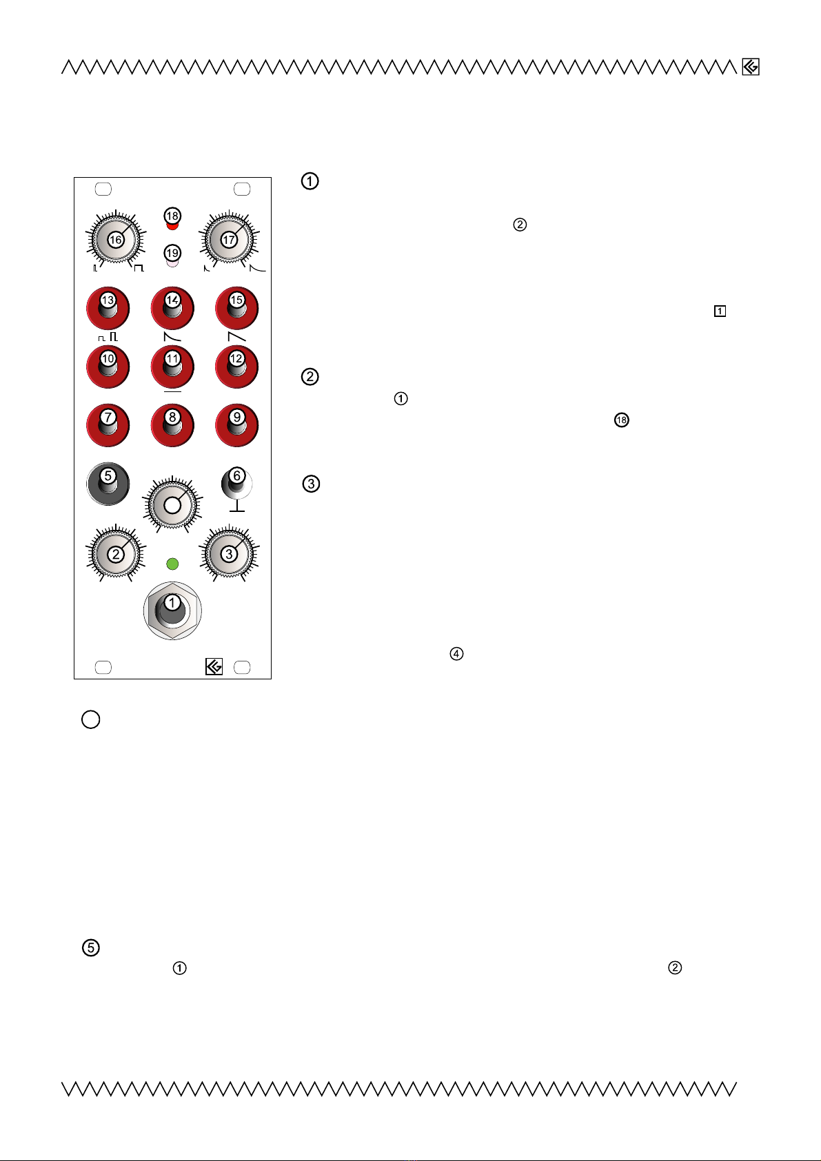
1
PEAK+HOLD
Drum In
P+H P+H
Audio Envelope Gate
In 2
log
P+H
ReleaseImpulse
Filter
2
3
4
5
6
7
82
3
4
5
6
7
8
Input Level
1
2
3
4
5
0
6
7
8
Trigger
1
2
3
4
5
0
6
7
8
2
3
4
5
6
1
7
8
9
Modular
3. Functions
Drum In (1/4' jack socket) Input for a percussion instrument
pickup (or rhythm machine output etc.). Its level is adjustable
with the "Input Level"-knob . The sensitivity of the input is
suitable for many pickups such as the optional piezo pickup or
for line outputs, but not for microphones.
Impedance is ≈ 300kΩ.
The input sensitivity is adjustable by the internal trimmer
23456789
21
10 11 13 14 15 16 17 18 19
20 22
12
Objekt in Pfade:
4
4
14
Falsche Zahlen
4
(Read chapter 5:
Adjustments
)
Input Level The input level control for the jack socket input
"Drum In" . For the best dynamic range adjust this knob
clockwise until the red limit indication LED even lights for very
loud input sounds.
Trigger Threshold Input sensitivity of the internal schmitt-
trigger comparator. The trigger point adjusted by this knob
resets the P+H and prepares it for the next (percussive) input
sound. The more this knob is turned clockwise, the more
sensitive the P+H becomes to low input and pianissimo tones,
but also to noise and unwanted signals such as vibrations etc..
One should find a compromise between good input sensitivity
and low susceptibility to interferences; even in combination with
the "Filter"-knob .
Filter This is a special lowpass filter affecting only the falling edges of the internal envelope/
differentiator signal. It ensures minimal latency and best response to the input drum sounds.
With regards to the large variety of percussive sounds this filter allows good adaption for most
purposes. For very short and high sounds such as clicks or woodblock sounds, the filter knob
can be turned far to the left (ccw). This makes the P+H's reaction very fast and sensitive.
For long sustaining sounds such as cymbals, metallophones and/or low frequency tones (like
tomtoms or base drums) the controller knob should be turned further clockwise to make the
processor more unsensitive to low frequencies and subaudio oscillations (which may cause a
premature interruption of the P+H signal). Please note, the reaction becomes slower the further
right the filter knob is turned.
Input 2 2nd audio input socket. The signal applied on this input will be added to the signal of
'Drum In' or may replace it, but it is not affected by level controller "Input Level" . This input
is intended for applying a 2nd signal source like from a drum machine or for cascading 2 or more
Peak+Hold
s (Please read chapter 4
Settings
and chapter 5
Adjustments
for further settings and
advanced control options)
2
PEAK+HOLD
Drum In
P+H P+H
Audio Envelope Gate
In 2
log
P+H
ReleaseImpulse
Filter
2
3
4
5
6
7
82
3
4
5
6
7
8
Input Level
1
2
3
4
5
0
6
7
8
Trigger
1
2
3
4
5
0
6
7
8
2
3
4
5
6
1
7
8
9
4
23456789
21
10 11
12
13 14 15 16 17 18 19
20 22
12
Objekt in Pfade:
23456789
21
10 11
12
13 14 15 16 17 18 19
20 22
12
Objekt in Pfade:
2 3 456789
21
10 11
12
13 14 15 16 17 18 19
20 22
12
Objekt in Pfade:
23456789
21
10 11
12
13 14 15 16 17 18 19
20 22
12
Objekt in Pfade:
4
23456789
21
10 11
12
13 14 15 16 17 18 19
20 22
12
Objekt in Pfade:
4

Modular
Ground This socket only exists in the
banana
version of the
Peak+Hold
. The ground connection
is required if the module is connected to external equipment, e.g. a rhythm machine. Within the
eurorack modular system the module is grounded by its power supply and the casing.
Audio Out The input signal applied to (preamplification or attenuation level adjustable with
), mixed with the signal applied on "In 2" is provided at this socket; useful for further signal
processing and/or cascading 2 or more
Peak+Holds
(See also chapter 4:
Settings
, and chapter 5:
Adjustments
).
Envelope Out The audio input signal is internally rectified and low-pass filtered (The filter
settings are partially adjustable with knob "Filter" ); the resulting envelope shape is accessible
at this socket.
Gate (Trigger) Out Positive rising trigger (gate) signal with a signal level from 0 to +5V, suitable
for triggering of e.g. external envelope generators.
Note:
The envelope signal which generates the trigger signal is internally differentiated, resulting
in a quite short GATE output signal!
Peak+Hold Out The P+H processor detects the signals highest level and keeps it as a hold
signal. The next incoming signal resets the Peak+Hold by triggering at the very beginning and
the next Peak+Hold value will be set. The trigger threshold level is adjustable with . The
provided P+H output voltages are in a range between 0 and +10V (also dependent on settings of
controllers and ).
Peak+Hold inverse Out The inverted Peak+Hold signal, in a positive range from +10V to 0V;
suitable e.g. in combination with output "P+H" to control 2 V As for panorama effects.
Peak+Hold logarithmic Out The Peak+Hold signal (accessable on socket ) converted to a
logarithmic voltage. Many V As (and also frequency V inputs from most V Os and V Fs) are
working with exponential V inputs for aurally correct perception. Because the P+H output V is
already proportional to the incoming audio intensity, it must converted to a logarithmic (anti
exponential) response to control these V inputs adequately.
Impulse Out Dynamic impulse output e.g. for triggering Delays or V Fs. The width of the
impulse can be regulated with the "Impulse"-knob .
Release Out The dynamic impulse signal (accessible on socket ) equipped with a falling
envelope shape. Length of the falling shape can be adjusted with "Release"-knob
2 3 456789
21
10 11
12
13 14 15 16 17 18 19
20 22
12
Objekt in Pfade:
4
.
Release logarithmic Out The logarithmic converted Release Out signal ; especially useful for
V A V inputs (See under ).
3
23456789
21
10 11
12
13 14 15 16 17 18 19
20 22
12
Objekt in Pfade:
4
2 3 456789
21
10 11
12
13 14 15 16 17 18 19
20 22
12
Objekt in Pfade:
4
23456789
21
10 11
12
13 14 15 16 17 18 19
20 22
12
Objekt in Pfade:
4
23456789
21
10 11
12
13 14 15 16 17 18 19
20 22
12
Objekt in Pfade:
4
23456789
21
10 11
12
13 14 15 16 17 18 19
20 22
12
Objekt in Pfade:
4
23456789
21
10 11
12
13 14 15 16 17 18 19
20 22
12
Objekt in Pfade:
4
23456789
21
10 11
12
13 14 15 16 17 18 19
20 22
12
Objekt in Pfade:
4
2 3 456789
21
10 11
12
13 14 15 16 17 18 19
20 22
12
Objekt in Pfade:
4
2 3 456789
21
10 11
12
13 14 15 16 17 18 19
20 22
12
Objekt in Pfade:
4
2 3 456789
21
10 11
12
13 14 15 16 17 18 19
20 22
12
Objekt in Pfade:
4
Modular
Impulse Time Regulates the length of the dynamic impulses at output "Impulse" . It also
influences the shapes of the "Release" - and "Release log" -outputs.
Release Time Adjusts the length of the release shape of the Release" - and "Release log" -
output signals .
LED "Saturation" This LED indicates when the
P+H
's outputs reach their maximum level and no
further dynamic expression or increase is possible. It is recommended to adjust the input
amplification ( ontroller "Level" ) such that this LED only lights for very loud input sounds or
very hard drum beats.
LED "Impulse" Indicates the generated impulse signal (Output "Impulse" ) and is also useful
for optical control to see if the
P+H
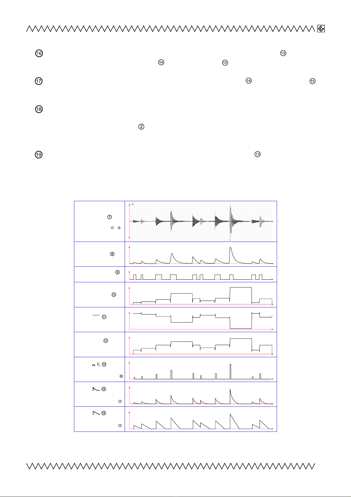
is working properly.Overview of Output Signals
Examples of typically generated waveforms
(Input: Rhythm machine)
4
t
+V
t
+V
t
+V
t
+V
t
+V
-V
t
+V
t
+V
t
+V
t
+V
Audio Out
Preamplified or attenuated
audio signal from Input or
Envelope Out
Trigger (Gate) Out
(Positive going edge)
Peak Hold Out
P+H
Pea +Hold inverse Out
log
P+H
Pea +Hold logarithmic Out
Impulse Out
Impulse width adjustable with
Release Out
Release time adjustable with
Release logarithmic Out
Release time adjustable with
23456789
21
10 11
12
13 14 15 16 17 18 19
20 22
12
Objekt in Pfade:
4
2 3 456789
21
10 11
12
13 14 15 16 17 18 19
20 22
12
Objekt in Pfade:
4
2 3 456789
21
10 11 13 14 15 16 17 18 19
20 22
12
Objekt in Pfade:
4
4
14
Falsche Zahlen
4
23456789
21
10 11 13 14 15 16 17 18 19
20 22
12
Objekt in Pfade:
4
4
14
Falsche Zahlen
4

Modular
4. Settings
Pickup
There is a pickup and double-sided adhesive tape included to the Peak+Hold module package by
standard, so it is easy to connect the P+H to any percussive instrument. The pickup is equipped with
1/4' jack and 2m cable.
Suggestions:
on tabletop wooden board bongo drum cymbal
Recommended filter settings for different instrument inputs (Knob )
Attaching the Pickup
ut off a piece of ca
2,5x2,5 cm² from the tape
Pull off the paper from one
side
Fix it on the metallic side
of the pickup
ut off the overhanging
edges
Pull off the second paper Fix it on the instrument
Note: The pickup cable is very microphonic; to avoid unwanted triggers it should be fastened, e.g.
on the drum stand.
Frequency-selective mode
It is possible to limit the audio signal's frequency range for the
further internal processing. This allows advanced settings especially
when working with two P+H modules. As well as this, unwanted noise
may be minimized by reducing very low or very high frequencies.
There are two trimmers
2 3 456789
21
10 11 13 14 15 16 17 18 19
20 22
12
Objekt in Pfade:
4
4
14
Falsche Zahlen
4
and
23456789
21
10 11 13 14 15 16 17 18 19
20 22
12
Objekt in Pfade:
4
4
14
Falsche Zahlen
4
on the backsided P B (nearby the
power supply connector) creating a simple adjustable highpass-lowpass filter combination.
Note:
There
is no ability to listen directly to the filtered audio signal; it only affects the processed V outputs. The
Audio Out always provides the full-frequency range signal. Please also read chapter
5.Adjustments
for more information.
5
Filter
2
3
4
5
6
1
7
8
9
Filter
2
3
4
5
6
1
7
8
9
Filter
2
3
4
5
6
1
7
8
9
Filter
2
3
4
5
6
1
7
8
9
Highpass Lowpass

Modular
Full frequency range High cut Low cut
Typical settings of the filter trimmers
23456789
21
10 11 13 14 15 16 17 18 19
20 22
12
Objekt in Pfade:
4
4
14
Falsche Zahlen
4
and
2 3 456789
21
10 11 13 14 15 16 17 18 19
20 22
12
Objekt in Pfade:
4
4
14
Falsche Zahlen
4
.
Example:
Two Peak+Holds are patched together. The
pickup amplitude for both P+Hs is controlled by
the knob 'Input Level' of the 1st P+H. 'Audio
Out' of the 1st P+H is sourcing the 2nd P+Hs 'In2'
input.
The filter trimmers
2 3 456789
21
10 11 13 14 15 16 17 18 19
20 22
12
Objekt in Pfade:
4
4
14
Falsche Zahlen
4
and
2 3 456789
21
10 11 13 14 15 16 17 18 19
20 22
12
Objekt in Pfade:
4
4
14
Falsche Zahlen
4
are creating a
lowpass characteristic filter for the 1st P+H and a
highpass filter for the 2nd P+H. Depending on the
amount of overtones and/or fundamentals of the
drum signal the two P+Hs will be controlled
differently, allowing one to create very colourful
and 3dimensional sounds with the V outputs.
P+H1 P+H
Patch for 2 Peak+Holds in fre uency-selective mode
6
Modular
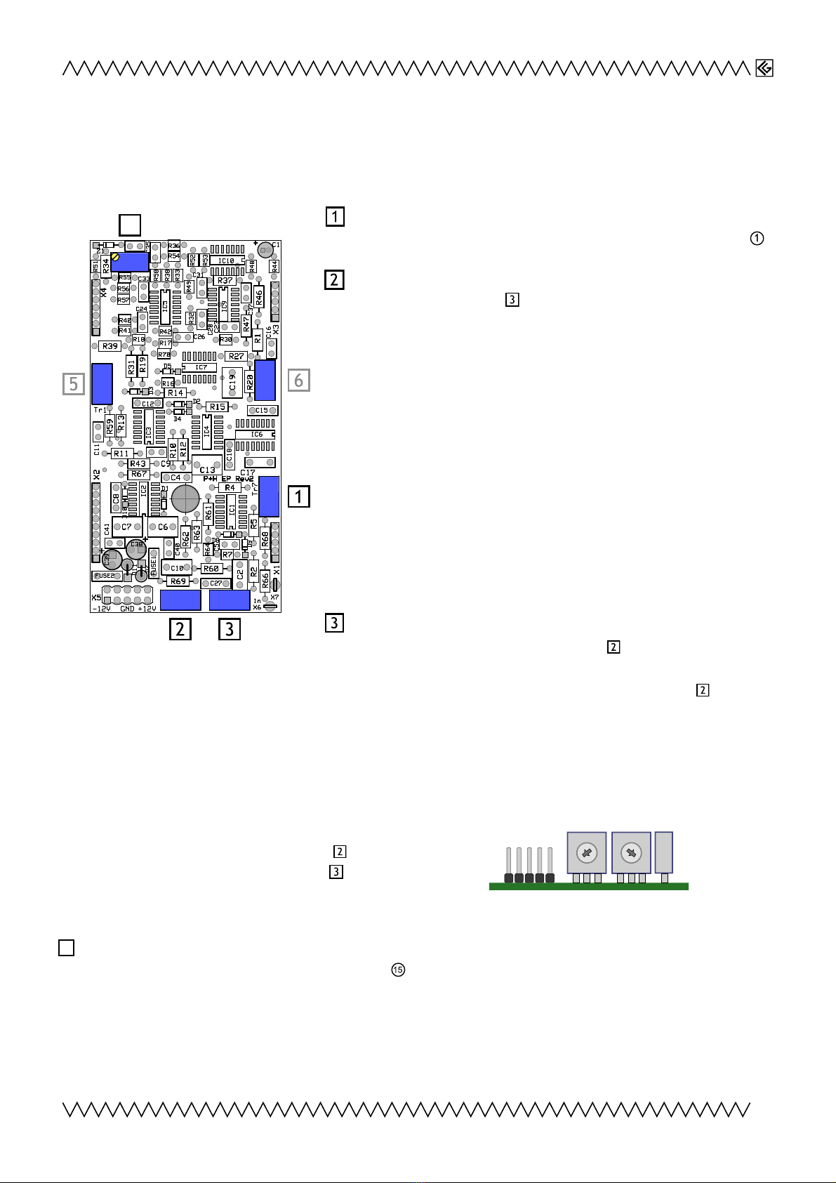
5. Adjustments
Backside P B view:
Preamp Gain
This Trimmer sets the preamplification for input "Drum In" .
Hipass Filter
Together with trimmer
2 3 456789
21
10 11 13 14 15 16 17 18 19
20 22
12
Objekt in Pfade:
4
4
14
Falsche Zahlen
4
(lowpass filter) a simple filtering
option is created. This special feature allows control over the
P+H by selecting the inputs frequency band. ombining two
or three P+H modules run from one input source, the
frequency range can be split to high and low or high, middle
and low frequencies, such that each P+H gets its own specific
frequency band resulting in e.g. overtone or bass preferring
P+H control.
Note:
There is no extra output for the filtered signal, the
settings have to be done by trying-out or by visual control of
the trimmer's position.
The trimmer fully turned left: full frequency range. The more
the trimmer is turned clockwise, the more the low frequencies
will be cut off.
Lowpass Filter
Together with highpass filter trimmer
2 3 456789
21
10 11 13 14 15 16 17 18 19
20 22
12
Objekt in Pfade:
4
4
14
Falsche Zahlen
4
, this provides the
option of audio signal filtering to achieve highpass, lowpass or bandpass characteristics for the further
signal processing. This allows frequency selective control of the Peak+Hold (Read also about
2 3 456789
21
10 11 13 14 15 16 17 18 19
20 22
12
Objekt in Pfade:
4
4
14
Falsche Zahlen
4
Highpass Filter).
Note:
There is no abilty to listen directly to the filtered audio signal.
The trimmer fully turned right: full frequency range. The more the trimmer is turned ccw, the more the
high frequencies will be cut.
Please also read chapter 4:
Settings,
for further explanation and examples.
Default settings of the filter trimmers
2 3 456789
21
10 11 13 14 15 16 17 18 19
20 22
12
Objekt in Pfade:
4
4
14
Falsche Zahlen
4
(left, highpass)
and
23456789
21
10 11 13 14 15 16 17 18 19
20 22
12
Objekt in Pfade:
4
4
14
Falsche Zahlen
4
(right, lowpass)
Logarithmic Amplifier 0-point adjustment
Especially for the Release logarithmic output , in 0-point sensitive applications such as controlling
the G-Products
XR22V O's
AM input, but also in frequency controlled applications, a divergence to
exactly 0 V from the 0-point may be annoying. It is possible to readjust the 0-point precisely with
this trimmer.
7
23456789
21
10 11 13 14 15 16 17 18 19
20 22
12
Objekt in Pfade:
4
4
14
Falsche Zahlen
4
23456789
21
10 11 13 14 15 16 17 18 19
20 22
12
Objekt in Pfade:
4
4
14
Falsche Zahlen
4
2 3 456789
21
10 11 13 14 15 16 17 18 19
20 22
12
Objekt in Pfade:
4
4
14
Falsche Zahlen
4
4
23456789
21
10 11 13 14 15 16 17 18 19
20 22
12
Objekt in Pfade:
4
4
14
Falsche Zahlen
4

Modular
The following is for completeness, however these settings should not be adjusted:
Schmitt-trigger Hysteresis of the internal schmitt-trigger comparator. If you have accidentally
shifted the settings, readjust the trimmer to mid position (12 o'clock).
Monoflop1 Length of the minimal delay time required for amplitude detection before the Impulse
Out signal is set. In the case of accidentally shifting the setting, readjust it to a mid position (12
o'clock).
. Contact & Support
Product homepage with soundfiles: http://www.cg-products.de/module/ peakhold/
Soundfiles on https://soundcloud.com/cg-products/sets/peakhold
Christian Günther
Forster Str. 50
10999 Berlin
Phone: ++49 30 61286299
Mobile ++49 178 7699267
www.cg-products.de
© Christian Günther Jan 2016
8
23456789
21
10 11 13 14 15 16 17 18 19
20 22
12
Objekt in Pfade:
4
4
14
Falsche Zahlen
4
23456789
21
10 11 13 14 15 16 17 18 19
20 22
12
Objekt in Pfade:
4
4
14
Falsche Zahlen
4
Table of contents
Popular Measuring Instrument manuals by other brands


Rockwell Automation
Rockwell Automation Allen-Bradley 1440-TBS-J installation instructions

Withings
Withings Sleep Analyzer Quick installation guide

Vaisala
Vaisala HUMICAP HMP155 user guide

senva
senva EM Pulse Series installation instructions

Water Specialties
Water Specialties Propeller meter ML03 Operation and maintenance manual

Agilent Technologies
Agilent Technologies 2100 Bioanalyzer System user guide


