CG XR1-E User manual

XR1-E
Ring Modulation Oscillator
Analog Effect Device
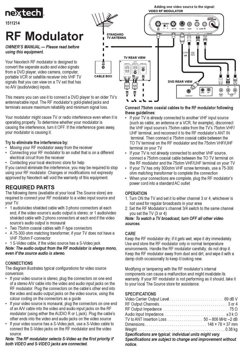
The XR1-E is an analog ring modulator device with internal oscillator, suitable for
instrument or microphone input.
The oscillator frequency is adjustable by manual control (coarse and fine over a wide
range. In addition, it can be modulated by an internal LFO (low frequency oscillator and/or
an envelope follower. If applied, an external CV (control voltage or pedal may be also used
for frequency modulation. Original and effect signal are miscible, but the XR1-E also
provides a footswitch input for external switching between effect and original. In this case,
the XR1-E provides true bypass routing.
Further, the ability of battery operation makes the device independent from external power
supply (6x AA mignon cells .
The XR1-E is based on a function generator chip, which warm and smooth sound makes it
excellently suitable for electronic music and ring modulation.
Low noise preamp
Ring modulation oscillator frequency range:
High: 8Hz – 18000 Hz
Low: 0.1 Hz – 60Hz
Envelope follower and LFO for frequency modulation
Frequency CV input (1V/oct adjustable), also suitable for pedal use
Footswitch control socket (true bypass)
Battery operation or external DC power supply (wide voltage range: 6-1 V)
Power dissipation: ca 1000mW (operation time with zinc-carbon cells ca. 4-8h)
1

Quick start guide
1. Insert batteries or accus (6x AA Mignon) or connect a power adaptor (DC 9-16V, +-pole:
the outer side of the plug). Set the power switch upwards to "On". Connect an amplifier,
mixer etc. to the output and connect an instrument or microphone to the instrument
input .
2. Set the frequency selector switch on "Hi". Turn the "Frequency" knob in middle
position.Turn the bypass pot in fully right position : "100%". Turn the envelope and LFO
modulation knobs , in fully left position: "0".
By calibrating the "Carrier Surpression" pot while listening to the oscillator tone, adjust
the tone to its minimum (≈ "0" on the scale/ denter locked; you may also use the green LED
for indication).
Adjust the "Preamp" input gain controller while playing your instrument and listen for
optimal performance.
NOTE: It is not possible to eleminate the carrier (oscillator) tone completely. There will
always remain some overtone frequencies. Try to set the input pot on a high level (with
acceptable distortion) to achieve best operation.
3. When using an external footswitch for dry/wet control, adjust 'Output Gain' Trimmer for
same output amplitude of the effect signal and the dry original.
2
Instrument Footswitch
Output Frequency
CV in
On/
Off
DC in
+
-
6-15V
XR1-E
Inversion
Envelope/e t.
Modulation
LFO
Modulation
Preamp BypassCarrier Surpression
Fine Adj.
Lo
Hi
LFO Mode
Waveform
Frequency
LFO
Frequency
-3
-2
-1 0+1
-4
+2
+3
+4
5
6
7
8
1
2
3
4
0
5
6
7
8
1
2
3
4
0
6
7
8
9
2
3
4
5
1
6
7
8
9
2
3
4
5
1
0
+
_
0100%
1
2
3 4
5
678
9
10
11
12
13
16
17
18
19
15
14
Output
Gain

In-/Outputs and Control Elements
①On/Off Switch
Switches the power supply on or off.
ote: In combination with an external power adaptor only the XR1-E will be switched off
and not the power adaptor itself. This means that the power adaptor still may consume
some current for its own ("stand-by"). It is recommended to disconnect the adaptor
completly from public power supply if the XR1-E is not in use for a of longer time .
②External Power Supply Input
Allows the operation with an external standard DC power adaptor. The connection is a
standard DC plug with 2.1mm diameter hole. By using the external power supply input ,
the internal batteries will be switched off. The input voltage range is 6V – 1 V. Max.
current dissipation is ca. 1 0mA (at 9V: ≈ 120mA). Take care on right polarity: The "+"pole
is the outer contact.
③Output
Connection to the following stage, e.g. an amplifier.
The output amplitude can be calibrated by trimmer 'Output Gain' .
Maximum output swing is ≈ 0,8V (Output trimmer fully turned up)
④Output Gain
This trimmer sets the gain for the processed output signal, allowing to align the effect
signal to the dry input signal, when using a bypass switch inserted to ('Footswitch').
(Only from Rev.2.5)
⑤Instrument Input
Input jack for instrument or microphone. Impedance: ca 380kΩ; max. input voltage:
≤3. Vpp.
⑥Preamp Gain Control
Adjustment of the the input preamp's amplification for the instrument input . The
preamp is feeding the oscillator's amplitude modulation input. It is necessary to adjust the
preamplification properly for best performancy. The input signal should be not distorted,
but also not too soft for the best effect-to-noise ratio.
⑦Carrier Surpression Control
Controller for calibrating the oscillator (carrier) tone to its minimum. The "0" position in the
middle of the scale / the potentiometer's denter locked may be used as reference point, as
well as the green LED – when dark (and without input signal) – is suitable for indication of a
minimum carrier tone amount.
ote: There will always remain a little bit of the oscillator sound (2nd harmonics etc.). For
best performance, make sure that the input signal level is high.
⑧Bypass Control
Ratio between input signal (preamplified) and effect signal. Turning the knob fully left will
provide the preamplified input signal only; by turning the knob clockwise the effect signal
will increase more and more and the original (dry) signal will disappear.Fully right position
= "100%": the pure ring modulation effect signal.
3

⑨Footswitch Input
Input jack for external bypass (dry/wet) control, e.g. by a footswitch
•Switch closed: The dry original input signal (true bypass)
•Switch opened: The effect signal (also depending on postion of the "Bypass"
control knob )
The switching also can be controlled by an external logic signal (0V = effect , + V = dry),
e.g. a gate signal from a synthesizer.
To align the output amplitudes of the dry and wet signal, adjust the processed output
signal with 'Output Gain' trimmer .
⑩Oscillator Frequency High/Low Switch
Hi: ≈ 8Hz – 18000 Hz (Audio range)
Lo: ≈ 0.1 Hz – 60 Hz
In "Hi" position, the oscillator is mainly working in audio range. The amplitude modulation
will generate additional audio frequencies – sum and difference tones of the input signal
and the oscillator frequency.
In "Lo" position, the oscillator is working with subaudio frequencies. The amplitude
modulation result is a tremolo-like sound. Volume of the input signal will change
constantly with the oscillator frequency.
⑪Oscillator Frequency Control
Coarse adjustment of the amplitude modulation (AM) oscillator frequency.
⑫Oscillator Frequency Fine Adjustment Control
Fine tuning of the oscillation frequency. Range is about 4 – semitones (quarte).
⑬Oscillator Waveform Switch
The oscillator waveform can be selected between sinewave and triangle. In " " (sine)
position, the effect is a more smooth sound with less overtones; in " " (triangle) mode the
generated sounds are rougher and with more overtones.
⑭LFO Frequency Control
Speed control of the internal LFO (low frequency oscillator) for frequency modulation of
the ring modulation oscillator. Frequency is from ≈0.06Hz (left position ) to ≈ 44Hz (right
position)
The LFO frequency is also displayed by the orange LED for visual control.
⑮LFO Modulation Depth Control
Amount of LFO modulation depth
⑯LFO Waveform Switch
The LFO waveform can be selected between triangle (" ") and square (" ")." " will
provide a continously up-and down gliding pitch, while " " makes the oscillator shifting
between two tones.
⑰Envelope Follower/ext. CV Modulation Depth Control
The internal envelope follower converts the volume of the input signal on the instrument
input into a control voltage modulating the oscillator frequency. Amount of modulation
can be varied by this knob.
If the external frequency CV (= Control Voltage) input is used, the internal envelope
follower will be switched off; instead the signal on can be adjusted by this pot (frequency
modulation depth).
4

⑱Envelope Follower Modulation: Inversion Switch
Switches the modulation polarity (from envelope follower or an external source on )
from positive to negative. If the switch is in upper position, the pitch of the AM oscillator
will increase with higher volume of the input signal. switch in lower position (= "Inversion")
the pitch will decrease with higher input volume. The inversion switch works also for a
control voltage signal connected to .
⑲External Frequency Control Input
Allows to control the oscillator pitch by an external control voltage (CV) or an external
resistor. By connecting a jack to this input, the internal envelope follower will be shut off
and instead the fed in control voltage will modulate the oscillator's frequency; the
modulation depth can be adjusted by knob .
The modulation CV's polarity can be inverted by switch . Normally, a higher voltage will
cause a higher pitch and vice versa. With in lower postion ("Inversion") a higher voltage
will cause a decreasing pitch and vice versa.
Further, a + V DC voltage (via 10kΩ resistor) is provided on , available on the middle
connector of a 3pole jack plugged in . Thus may be useful, for example, in combination
with a sensor or a pedal. In the latter case, a common passive foot pedal with 3pole jack
should work.
In combination with analog synthesizer equipment (e.g. sequencers, monophone
keyboards), it is possible to calibrate the XR1-E on 1V/Oct. by adjusting knob .
To calibrate on 1V/Oct for tracking with other instruments, connect the
external CV source to and set the pointer of the "Envelope/
ext.Modulation" controller to nearby "7" on the scale. This is a good base.
Then adjust by listening with different CV values until the pitch matches
with the pitch of your instrument.
Envelope/e t.Modulation
1
2
3
4
5
0
6
7
8
17

About Ring Modulation
Ring modulation is the multiplication of two bipolar audio signals by each other. Each value of a
carrier signal, C, is multiplied by a modulator signal, M, to create a new ring-modulated signal, R:
R(t) = C(t) x M(t)
(from: http://en.wikibooks.org/wiki/Sound_Synthesis_Theory/Modulation_Synthesis)
It is referred to as "ring" modulation because the analog circuit of diodes originally used to
implement this technique took the shape of a ring (Wikipedia).
For example: If one or both of the input signals C or M is 0V, the output R will be also 0V.
ote: In the case of the XR1-E the carrier signal is or , provided by the internal oscillator.
Examples
Input (=modulator signal frequency >> oscillator (carrier frequency ( :
Input signal: metallophone
The volume of the metallophone sound varies with the oscillator amplitude.
Input (=modulator signal frequency << oscillator (carrier frequency (
Input signal: "Base drum" from rhythm machine The generated effect signal
The volume of the oscillator sound varies with the amplitude of the input signal
Input (=modulator signal frequency ≤ or ≥ oscillator (carrier frequency (
Input signal: "Mid tom" from rhythm machine
Complexe sound structures are generated, depending on the oscillator frequency.
6

Support
Christian Günther
Forster Str. 0
10999 Berlin
Phone: ++49 30 61286299
Mobile ++49 178 7699267
www.cg-products.de
XR1-E website with video and soundfiles: http://www.cg-products.de/xr1-e/
Youtube: https://www.youtube.com/watch?v=2zDMeQAN_4I
Soundcloud: https://soundcloud.com/cg-products/sets/xr1-e
This documentation is for XR1-E Rev.3.0/2.5
www.cg-products.de/XR1-E_documentation.pdf
Version Rev.2 (without ):
www.cg-products.de/XR1-E_documentation_Rev2.0.pdf
For the version Rev.1 (with output high/low switch and without true bypass):
www.cg-products.de/XR1-E_documentation_Rev1.pdf
© Christian Günther
7
Table of contents


