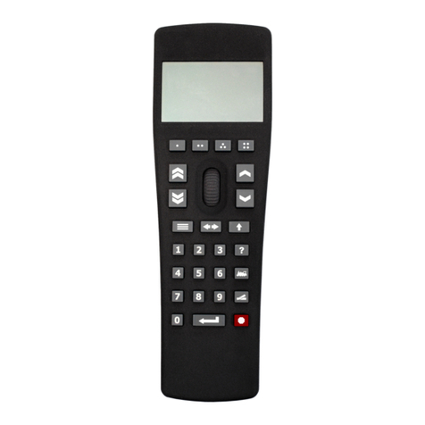
CH-SYS SC-406S User manual

Speed Control SC-406S
USER MANUAL
操作使用說明書
第0頁

Contents
1. Functions of Control Panel.................
2
2. External Dimension for Installation......
3
3. Standard Connection...............
4
4. Explanations of Terminals...............
5
5. Parameters Setting Method................
6
6. Parameters Table....................
6
7. Parameter 01 Programming...............
7
8. Parameters Explanation...................
8
EMAIL:[email protected]
Http://www.ch-sys.com
第1頁

1.Functions of Control Panel
SPEED CONTROLLER
Red LED
Speed Value
SPEED
○RUN
○PRG
○ERR
Operation Indicator
Programming Indicator
Alarm Indicator
SPEED
SET Green LED
SpeedSetting
▲▼
Deceleration Button
Parameter in
p
ut
Parameter selection
A
cceleration Button
Addition function:
1. Method for modifying setting:
MODE+ ▲→from low to high (Acceleration)
MODE+ ▼→from high to low (Deceleration)
2. Method for moving decimal point:
SET+ ▲or ▼to move the decimal points from left to right.
EMAIL:[email protected]
Http://www.ch-sys.com
第2頁

2.External Dimension for Installation
SPEED CONTROLLER
○RUN
○PRG
○ERR
SPEED
SET
SPEED
100m/m
100m/m
160m/
m
CH SC-406s
90m/m
Panelopening:92x92m/m
EMAIL:[email protected]
Http://www.ch-sys.com
第3頁

3.Standard Connection
※Metal-shielded and isolated cable is necessary.
1. As Terminals 15 & 17 are short-circuited to modify parameters, please
open Terminals 15 & 16.
2. After finishing system adjustment, please open Terminals 15 and 17 to
avoid parameters modified.
3. D/A and signals wirings don’t set near or with power lines.
4. When the distance of signal cable is far from master (motor/inverter and
so on), please add isolated interface.
EMAIL:[email protected]
Http://www.ch-sys.com
第4頁

4.Explanations of Terminals
Power source Terminals 1 & 2 are AC power input.
Specification: AC 220V ± 3% 50/60 Hz
Terminal 3 is F.G. (earth contact)
E1 and E2 Terminals 9 (+) and 10 (-) are power source of
Encoder inputs encoder, DC 12V±10%, 100mA (MAX)
Terminals 13 & 14 are feedback signal from the motor.
Start System Terminals 15 & 16 are to start system. It is auto-control
model when short-circuited of starting terminal.
Parameters Short-circuited Terminals 15 & 17 for modifying parameters
Setting content,detailoperation methods, please refer to page 5.
Speed Terminals 15 & 18 are speed acceleration contact A.
Adjustment Terminals 15 & 19 are speed deceleration contact A.
D/A Output Terminals 20 & 21 are D/A output 0~10V to
inverterorDCcontroller.Pleaseusemetal-shieldedcable
and isolated to power lines.
※Power source (+) and (-) must not be reversed.
EMAIL:[email protected]
Http://www.ch-sys.com
第5頁

5. Parameters Setting Method
Example: Please short-cut terminal 15 & 17 and open terminal 15 & 16
Step 1. Press MODE button
PRGblink 01
0004
Step 2. Press ▲or ▼button to modify value
PRGblink 01
0005
Step 3. Press SET button to confirm the value modification finished.
000.0
100.0
Accomplishing setting, system will return to normal display operation after a
few seconds. If you need to modify other parameters, please repeat the
procedure above. Press MODE button on and on, the red LED will display
parameters 01~07 in a circle.
6.Function: Parameters Table
Parameter
No. Function Range Factory
Setting User
Setting
01 406s function selection 0-31 8
02 Response time 1-99 30
03 Time adjust for speed up
and down 1-99 30
04 Ratio “K” for main speed 100-9999 1000
05 Linear speed “K” 100-9999 1000
06 Upper limit of speed 0-9999 1000
07 *Additional
(Voltage per start) 0-255 30
*If the setting is 30, the result is 3 second.
Higher of the value of parameter 02 and 03 results slower response time.
Parameter 04, 05 and 06 have to modify depending on actual situation.
EMAIL:[email protected]
Http://www.ch-sys.com
第6頁

7.Parameter 01 Programming
The indicator of【◆】:406S equipped functions
Upper LCD Display
Content
Parameter
No. Range Position
Tracing V/R
Input Auto-signal
Feedback
for E1/E2
Recovery
(memory)
Function
Linear
Speed Signal-tracking
Indicator
0000 ◆◆
0001 ◆◆
0002 ◆◆◆
0003 ◆◆◆
0004 ◆◆◆
0005 ◆◆◆
0006 ◆◆◆◆
0007 ◆◆◆◆
0008 ◆◆◆
0009 ◆◆◆
0010 ◆◆◆◆
0011 ◆◆◆◆
0012 ◆◆◆◆
0013 ◆◆◆◆
0014 ◆◆◆◆◆
0015 ◆◆◆◆◆
0016 ◆
0017 ◆
0018 ◆
◆
0019 ◆◆
0020 ◆◆
0021 ◆◆
0022 ◆◆
◆
0023 ◆◆◆
0024 ◆◆
0025 ◆◆
0026 ◆◆◆
0027 ◆◆◆
0028 ◆◆◆
0029 ◆◆◆
0030 ◆◆◆◆
01
0031 ◆◆◆◆
第7頁

8.Parameters Explanation
Pr.01 406S Function selection
Setting range : 0 ~ 31
Factory setting : 8
Description : None
Pr.02 Response time
Setting range : 0 ~ 99
Factory setting : 30
Description : As the setting value is low (high), voltage compensation speed
will be fast (slow) and response time quickly (slowly).
Pr.03 Accelerating and decelerating time adjust
Setting range : 1 ~ 99
Factory setting : 30
Description : The set is for time from 0 to target time. Small value means
response quickly; on the contrary, high value means slow
response time because long time processed.
Pr.04 Main speed “K” value
Setting range : 100 ~ 9999
Factory setting : 1000
Description : Steps:
1. Set the speed you want in Pr.04.
2. Adjust panel display to be 1000.
3. Start processing, then detect actual (linear) speed.
4. Adjust panel display to make actual (linear) speed equal to
Pr04.
5. Change Pr04 to be the value of panel display.
EMAIL:[email protected]
Http://www.ch-sys.com
第8頁

8.Parameters Explanation
Pr.05 Main linear speed “K” value
Setting range : 100 ~ 9999
Factory setting : 1000
Description : After finishing the set of Pr.04, then start to process and check
whether the indicated value is the same as actual speed.
If there is different, you can modify both values (indicator and
actual speed) to be equal by buttons of MODE+▲or MODE-
▼.
Pr.06 Upper limit of speed
Setting range : 100 ~ 9999
Factory setting : 1000
Description : The setting of upper limit of speed.
Pr.07 Additional
Setting range : 0 ~ 255
Factory setting : 30
Description : During executing function, urgent accelerating time unit is 0.1
second/
For example:
Pr07=30, actual executed time is 3 second (30 x 0.1).
EMAIL:[email protected]
Http://www.ch-sys.com
第9頁

第10 頁
Table of contents
Popular Control System manuals by other brands
Dickey-John
Dickey-John Control Point Operator's manual
Graf
Graf ECO SMART Instructions for installing
Aveo Systems
Aveo Systems Mira Connect 10 installation instructions
Lionel
Lionel WiFi Layout Control System owner's manual
IDEC
IDEC EB3N manual

Mitsubishi Electric
Mitsubishi Electric BAC-HD150 Instruction book

