Dickey-John Control Point User manual

OPERATOR'S MANUAL
CONTROL POINT™ SYSTEM DESCRIPTION/ 1
11001-1100-199904 Revision A
CHAPTER 1 – SYSTEM DESCRIPTION
The DICKEY-john Control Point™ system uses three-channels (three separate
controlled servo loops) on spreader vehicles to simultaneously control the
spreading of granular and liquid ice-control materials. Two channels control
granular and liquid application rates and the third channel precisely controls
spinner speed to maintain even material coverage over the desired spread
width. The dispensing rate varies directly with ground speed to ensure accu-
rate product application.
Material can also be spread at a preset “BLAST” application rate. This is
normally a very large rate to instantly adjust the target APR (application rate)
for covering bridges and intersections with a much heavier amount of material.
GRANULAR CHANNEL CONFIGURATION
The granular channel controls the amount of material dumped onto the
spinner plate(s). To do this, the Control Point™ monitors a tachometer style
feedback sensor located on the V-box drag chain or tailgate auger. A resultant
drive signal adjusts the conveyor mechanism speed to deliver the target
application rate (APR) by regulating the hydraulic valve position.
Figure 1. System Components

OPERATOR'S MANUAL
2/ SYSTEM DESCRIPTION CONTROL POINT™
11001-1100-199904 Revision A
LIQUID CHANNEL CONFIGURATION
The liquid channel controls the application rate of prewetting or deicing
materials. When prewetting, the Control Point™ Console monitors a flowmeter
style feedback sensor. When deicing, either a flowmeter or pressure style
feedback can be used. Using feedback data, the pumping mechanism output
adjusts the target application rate by either regulating pump speed or flow
blocking.
Deicing systems use up to five boom inputs for applying material to more than
one lane at a time.
SPINNER CHANNEL CONFIGURATION
The spinner channel controls the spinner plate(s) speed with either a closed-
loop (precision) or an open-loop configuration. In the closed-loop configura-
tion, a tachometer style feedback sensor, mounted on the spinner assembly,
monitors spinner activity. Using the feedback data, the spinner mechanism
speed adjusts for the target setting by controlling the hydraulic valve position.
In open loop systems, the hydraulic valve position is relative to the WIDTH
ADJUST knob setting on the Control Point™ Switch Module.
The customer must determine the spread-width accuracy needed. DICKEY-
john Marketing and Product Service personnel are available with additional
information to help with this decision.
PRODUCT APPLICATION MECHANISMS
The granular and spinner channels use, in addition to feedback (shaft rotation)
sensors, either servo valve actuators or proportional valves to control the
product application and spinner speed. The liquid channel uses, in addition to
feedback sensors (flowmeter or pressure transducer), a liquid pump to control
product application. The liquid pump output is controlled by either a 12 volt
DC motor, servo valve actuator, or proportional valve.

OPERATOR'S MANUAL
CONTROL POINT™ SYSTEM DESCRIPTION/ 3
11001-1100-199904 Revision A
SYSTEM FEATURES AND CAPABILITIES
1. Easy installation - surface-mounting Console kit.
2. Switch Module located anywhere in the cab to allow optimum
placement for the operator.
3. Large 160X128 dot-matrix LCD display with backlighting for
nighttime viewing.
4. Single Console button for system power on/off and screen selec-
tion.
5. RS-232 port for PC uploading and downloading of data.
6. Detachable keyboard for easy supervisor programming and
calibration using multilevel, menu-driven screens.
7. Custom programming available to minimize setup time.
8. Compatibility with a variety of sensors, servo valve actuators, and
proportional valves available from DICKEY-john or other manu-
facturers.
9. Audible and visual alarms for system and operator errors.
SYSTEM COMPONENT DESCRIPTIONS
A DICKEY-john Control Point™ system consists of six basic components;
(1) Console, (2) Switch Module, (3) ground speed sensor, (4) feedback devices to
monitor material application, (5) actuator devices to regulate material application,
and (6) harnesses to interconnect all system devices. The detachable keyboard
(optional) and PC (not provided) are programming aids and not actually a part of
a basic Control Point™ system.
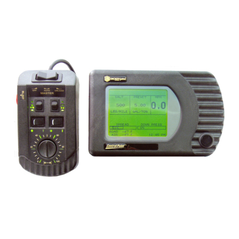
Figure 1 illustrates the Console, Switch Module, and keyboard. Figure 2 shows
components in a block diagram. The Console and Switch Module are located
inside the truck cab. These two items may be mounted side-by-side or the Switch
Module can be positioned for operator convenience.
A. Console
The Console displays information on a dot-matrix LCD and uses a single push-
button switch to control system power and to view several operator screens.
Using an external keyboard for programming and placing operator controls on
the Switch Module greatly simplify the Console.
An RS-232 port connector, located on the Switch Module harness, permits data
transfer to and from the Console. This port interfaces to a PC for downloading
accumulator and alarm information. When replacing a console or when identical
vehicles require programming/calibrating, uploading and downloading configura-
tion information through the port is extremely useful. For multiple units, only one
system needs to be programmed and then the constants can be transferred
(downloaded) from that console, stored in a PC file, and uploaded to the other
vehicle's console. Note: This is only useful on identical vehicles.

OPERATOR'S MANUAL
4/ SYSTEM DESCRIPTION CONTROL POINT™
11001-1100-199904 Revision A
B. Switch Module
The Switch Module harness plugs into the Console and contains connectors for
both keyboard and PC interface as described above.
The operator controls the real-time functions of the Control Point ™ system
from the seven switches on the Switch Module. (See Figure 3).
C. Keyboard
The keyboard is the means the operator uses to program and calibrate the
system. The 86-key, alphanumeric, PC-compatible keyboard has been environ-
mentally hardened for use in the ice-control field. After programming and
calibration are finished, the keyboard is usually disconnected and stored.
D. Ground Speed Sensor
The ground speed sensor generates vehicle speed information for the console.
Sensor electrical pulses proportional to the vehicle ground speed are vital to
system operation because true vehicle ground speed is necessary for accurate
product application. The system can function with a wide variety of electronic
and mechanical speedometer sensors, including Hall-Effect and Reluctance
sensors.
Figure 2. System Block Diagram

OPERATOR'S MANUAL
CONTROL POINT™ SYSTEM DESCRIPTION/ 5
11001-1100-199904 Revision A
E. Feedback Sensors
The feedback sensors send product flow information to the console for accurate
product application. Both granular and spinner channels require pulsed
electrical sensors having an output proportional to the mechanism speed. The
liquid channel accepts either electrical pulsed sensors or analog sensors with
outputs proportional to material flow (pulsed) or system pressure (analog). A
liquid prewetting system only accepts pulsed feedback while higher capacity
anti-icing systems accept either pulsed or analog.
F. Actuator Devices
Actuator devices regulate material flow for accurate control of product applica-
tion rates. Normally, granular and spinner channels regulate the hydraulic oil
flow rate to a motor. Liquid channels use several different configurations. Many
prewetting systems use a DC pump to regulate flow by controlling pump speed.
Other systems use hydraulically driven pumps similar to agricultural applica-
tions.
G. Hopper Level Sensor (Optional)
The optical light beam of this level sensor is blocked by the granular material in
the spreader bed. When the material level falls beneath the sensor mounting
level, a repetitive beep sounds and an appropriate message displays in the
warning/alarm area of the OPERATE screen.
I. Harnesses
The Main Harness assembly connects the Console to the ground speed sensor,
feedback sensors, channel valve (or DC motor) actuators, vehicle battery,
ignition, and additional optional connections (including two-speed axle, hopper
level sensor, and boom sense inputs). An optional Extension Harness, allows
the Main Harness to extend outside the cab, contains duplicate connectors to
permit hookup flexibility. Other extension harnesses are available to allow
flexible sensor arrangement.
HOW TO OBTAIN TECHNICAL SUPPORT
For prompt and courteous assistance and answers to your questions, call
DICKEY-john Technical Support at (217) 438-3371 or Fax (217) 438-6012 or
438-6539. For toll-free calls in either the USA or Canada, dial 1-800-637-3302.

OPERATOR'S MANUAL
6/ SYSTEM DESCRIPTION CONTROL POINT™
11001-1100-199904 Revision A

OPERATOR'S MANUAL
CONTROL POINT™ OPERATING PROCEDURES/ 7
11001-1100-199904 Revision A
CHAPTER 2 – OPERATING PROCEDURES
This chapter explains how the operator (driver) of an ice-control vehicle uses
the controls on the Switch Module and Console to perform standard operator
functions. Note: The detachable keyboard (optional) is required to program and
calibrate the system as described in the next Chapter.
Depending upon programming, the operator can view three or four different
screens of data. The OPERATE screen is the home screen for monitoring
spreader operation; the remaining screens are supportive – MATERIAL
SELECT/MANUAL SPEED, CURRENT TOTALS, and SEASON TOTALS.
The MATERIAL/MANUAL SPEED SELECT screen is only accessible if the
system is stationary (no ground speed).
PREPARING FOR OPERATION
Perform the following procedures only after the system is installed, properly
programmed and calibrated. Practice the following procedures with the vehicle
stationary to gain familiarity with the operating controls and screens before
applying product.
Figure 3. Switch Module Controls and Definitions

OPERATOR'S MANUAL
8/ OPERATING PROCEDURES CONTROL POINT™
11001-1100-199904 Revision A
STARTING THE SYSTEM
1. Verify the MASTER Switch on
the Switch Module is in the
OFF position (See Figure 3).
If the Master Switch is in the
AUTO position during power up,
a warning message with audible
alarm occurs until the switch is
turned OFF (See Figure 4).
2. Turn on the ignition switch.
If the Console was on when the
ignition was last turned off, the
display comes on with the
ignition switch. A screen briefly
shows the DICKEY-john logo
followed by the OPERATE screen (See Figure 6).
If the console does not power on, the console button was used to
properly power down the unit. Proceed to Step 3.
3. Briefly press the Console button (less than a second) to apply
power to the Console (See Figure 5).
If the button is held too long, a beep sounds indicating
the Operate screen is skipped and an accessory screen
appears instead (This screen described later). If the beep
is heard, turn the console off as indicated in Step 4 and
start again.
During start-up (power up), the Console automatically
closes all system actuators and performs self-tests, includ-
ing system configuration and application data. If an error
occurs at power up or during operation, an appropriate
error message displays with recovery information.
4. Turn the Console off by pressing and holding the
Console button until a beep sounds and the text on
the screen disappears (approx. 3 seconds) and then
release.
Power is removed when the screen goes dark. To restart,
repeat Step 3.
Figure 4. Master Switch
Warning Message
Figure 5. Console Showing Functional Items

OPERATOR'S MANUAL
CONTROL POINT™ OPERATING PROCEDURES/ 9
11001-1100-199904 Revision A
OBSERVING THE OPERATE SCREEN DIVISIONS
1. Study the OPERATE screen layout (See Figure 6).
Three windows across the upper portion display Granular, Liquid,
and true (actual) Ground Speed data. Directly above, status of the
booms graphically display. Below the windows, error messages
appear briefly for system errors along with an audible alarm. In the
lower third, the Spread Width Bar graphically indicates percentage
of spinner activity via a black bar. At the bottom, the current date
and time display.
2. At the Switch Module, turn the Granular and Liquid ON/OFF
switches off, then back on again (See Figure 3).
Notice, the window for each product reads OFF and then returns to
the material and target (APR) values again.
Ground speed is independent of product application and therefore
displays only when the vehicle is moving.
Product application begins with vehicle motion if the Master Switch
is in the AUTO position. The actual APRs display in roughly twice
the size of the target APRs (See Figure 7).
3. Change the target rate of either product channel by pressing
the respective “INC/DEC +/-” switch on the Switch Module.
The value increments/decrements as a beep is heard for each inc/
des step. If the switch is held, the value repeats until reaching a
preset limit. If changed while the vehicle is moving, the new target
APR displays for approximately two seconds, then reverts to the
actual APRs.
Figure 6. Divisions of the OPERATE Screen

OPERATOR'S MANUAL
10/ OPERATING PROCEDURES CONTROL POINT™
11001-1100-199904 Revision A
4. Rotate the WIDTH ADJUST knob on the Switch Module
while observing the SPREAD WIDTH bar on the display.
The rotational speed of the spinner changes with the knob setting.
The horizontal bar graphically represents the position of the
SPREAD WIDTH knob. The bar is at the 100% position when the
knob is fully clockwise, corresponding to maximum spinner speed.
The operator determines the correct setting by observing the spread
pattern. The bar is hollow until the spinner is operating.
5. Note the date and time across the bottom edge of the screen.
6. Observe the boom graphics across the top of the screen.
All boom sections appear as rectangle blocks during anti-ice
operation. Each section is hollow until activated.
7. Observe the area for alarm messages.
Alarm messages appear (flashing) in the middle of the screen, above
the SPREAD WIDTH bar (See Figure 7).
Figure 7. OPERATE Screen Showing Product Application

OPERATOR'S MANUAL
CONTROL POINT™ OPERATING PROCEDURES/ 11
11001-1100-199904 Revision A
MATERIAL/MANUAL SPEED SELECT SCREEN
This screen is divided into two major divisions. The Material Select portion
(upper half) lists the products programmed for use. The Manual Speed
portion (lower half) allows selecting of an artificial ground speed signal in the
event the standard ground speed sensor fails. Without a ground speed signal,
the system is inoperative unless manual speed operation is selected.
This screen can only be accessed if (1) the vehicle is stationary (zero ground
speed), (2) the MASTER Switch is in the OFF position, and (3) more than
one material is listed in either list or manual ground speed has been enabled
during programming.
A. Selecting a different Dispersal Material
1. Press the Console button and release immediately after a
beep.
Figure 8 illustrates the MATERIAL/MANUAL SPEED SELECT
screen showing four materials for each product channel enabled.
2. Verify that the Granular ON/OFF and/or Liquid ON/OFF
switches on the Switch Module are ON.
The channel ON/OFF switch must be ON to select a different
material.
3. Press the INC/DEC +/-” switch of the appropriate channel
(granular or liquid), in either direction, to move the point-
er up or down on the left side of either list.
Figure 8. Screens Available to
Operator by Cycling

OPERATOR'S MANUAL
12/ OPERATING PROCEDURES CONTROL POINT™
11001-1100-199904 Revision A
B. Substituting Manual Speed for Standard Speed Sensor
If the ground speed signal is lost, the system ceases to function. If this occurs
due to a loss of sensor, cabling problems, etc., an artificial ground speed signal
can be substituted to continue limited operation. The fixed ground speed must
be previously programmed and then can be selected from the MATERIAL/
MANUAL SPEED SELECT screen (See Figure 8).
1. Stop the vehicle and turn the MASTER switch OFF. From the
OPERATE screen, press the Console button and release after
the beep to access the MATERIAL/MANUAL SPEED SE-
LECT screen.
2. Press the BLAST button to change the selection as prompted
at the bottom of the screen.
Notice the line stating “MANUAL ON”. As the BLAST button is
pressed, NO changes to YES. Releasing the button reverts to the
OPERATE screen. The ground speed window now displays the
word MANUAL at the bottom.
3. Continue spreading material, maintaining displayed speed as
closely as possible, to ensure accurate application.
The system spreads material but no accumulators are updated since
system accuracy cannot be assured. The related sensor and harness
should be inspected and repaired as soon as possible to restore
normal operation.
C. Returning to the OPERATE screen
1. Press the Console button three times, waiting for the beep
before releasing, to cycle back to the OPERATE screen (See
Figure 8 for all screens).
The OPERATE screen now shows the material name(s) just select-
ed, along with the correct (programmed) target APR.
ACCESSING THE CURRENT TOTALS SCREEN
If MANUAL SPEED operation has been selected (see heading MATERIAL/
MANUAL SPEED), this must first be deselected before the CURRENT
TOTALS screen can be cleared.
1. From the OPERATE screen, press and release the Console
button after the beep. Press a second time, if necessary, to
display the CURRENT TOTALS screen (See Figure 9).
The MASTER Switch must be in the OFF position before any other
screen can be accessed.
The CURRENT TOTALS screen (See Figure 9) appears showing
totals accumulated for the current product selected.
To see other totals, return to the MATERIAL/MANUAL SELECT
screen and select those products.
Figure 9. CURRENT TOTALS
Screen

OPERATOR'S MANUAL
CONTROL POINT™ OPERATING PROCEDURES/ 13
11001-1100-199904 Revision A
CLEARING THE CURRENT TOTALS
The ability to clear the CURRENT TOTALS screen is programmable in
the Programming mode (See PROGRAMMING chapter). If so pro-
grammed, all totals on this screen should be recorded before clearing, then
proceed as follows.
1. With the Granular switch on, (top half of the screen), press
the Granular +/- (left) switch up and release when the
beep sounds.
A message “PRESS DEC TO CONFIRM CLEAR (product)
ACCUMS (accumulators)” appears.
2. Next, press the same switch down (decrement) and the
totals reset to zero (See Figure 10).
To clear the bottom half, repeat the steps for the liquid channel
with the Liquid +/- (right) switch (See Figure 11). Press the
console button to stop the clear operation.
ACCESSING THE SEASON TOTALS SCREEN
1. From the OPERATE screen, press and release the Console
button after the beep. Repeat until the SEASONS TOTAL
screen appears (See Figure 12).
This screen shows the amount
of material applied, miles
traveled during application,
and hours elapsed this season
for each product in both the
AUTO and BLAST modes.
The totals can only be cleared
in the Program Mode (key-
board).
Figure 12. SEASON TOTAL
Screen
Figure 10. Clearing top half of
CURRENT TOTALS Screen
Figure 11. Clearing Bottom Half
of CURRENT TOTALS Screen

OPERATOR'S MANUAL
14/ OPERATING PROCEDURES CONTROL POINT™
11001-1100-199904 Revision A
USING THE BLAST BUTTON
Pressing the red BLAST button (on the left side of the Switch Module) causes
material to dispense at a higher, programmed rate. The BLAST button per-
forms several functions, depending upon programming options.
1. With the Operate screen displaying, press the Blast button on
the side of the Switch Module.
When the Blast button is pressed, the Operate screen displays
BLAST ON above the SPREAD WIDTH bar.
This either initiates a timed blast cycle (programmed length) or
momentary (blasts only with the button pressed). A timed blast
period can be terminated early by activating the BLAST button a
second time. Blasting can be initiated with the MASTER Switch in
AUTO or OFF.
With a timed blast cycle, a programmed minimum ground speed
establishes the material flow rate until that speed is exceeded by the
actual ground speed.
MASTER SWITCH IN THE UNLOAD POSITION
The UNLOAD position of the MASTER Switch is used to quickly remove
material from the truck.
Warning: If the spinner is programmed to operate during UNLOAD,
be sure that no one is in the vicinity before performing this procedure
to avoid possible injury!
1. Back up to the appropriate location and momentarily press
UNLOAD.
The actuators open fully for those channels turned on from the
switch module.
2. To stop the unload operation, move the MASTER switch to
the OFF position.

OPERATOR'S MANUAL
CONTROL POINT™ KEYBOARD PROGRAMMING/ 15
11001-1100-199904 Revision A
CHAPTER 3 – KEYBOARD PROGRAMMING
Programming allows the operator to enter rates, limits, and other
parameters into the Control Point™ memory for regulating system
product application. These parameters are entered through a detachable
keyboard. Specifics include (1) calibration constants, (2) configuration
parameters (sensor and actuator specifications), (3) granular and liquid
material information, and (4) product application rates (APRs). It also
includes resetting system accumulators for vehicle mileage, material
usage, and time totals.
Programming must be performed before attempting system calibration.
Accurate system calibration constants are determined through regular
calibration routines. However, known constants at the time of program-
ming can be entered thus reducing the calibration procedures required.
Calibration corrections can be revised anytime to fine tune accuracy.
LOGGING CONFIGURATION DATA
All calibration constants and other system parameters should be re-
corded on the CALIBRATION DATA RECORD sheets at the rear of this
manual. In the event of Console damage or lost data, rapid recovery is
assured. If the Control Point™ Console ever requires replacement, all
values can be transferred directly to the new Console via the keyboard.
PREPROGRAMMING
Each Control Point™ system is shipped from DICKEY-john pre-pro-
grammed. Specific parameters can be custom pre-programmed by
DICKEY-john to minimize customer programming. This simplifies
calibration but final SYSTEM RESPONSE (See CALIBRATION chap-
ter) must be performed after installation on every truck.
Figure 13. Keyboard Layout and Functions

OPERATOR'S MANUAL
16/KEYBOARD PROGRAMMING CONTROL POINT™
11001-1100-199904 Revision A
USING THE KEYBOARD AND SCREENS
Programming and calibration is accomplished using the keyboard and on-
screen, menu-driven instructions. The keyboard (See Figure 13) detaches
and can be stored after programming and calibration is complete. To use
the keyboard, proceed as follows;
1. If the Control Point™ is on, turn the power off and then
connect the keyboard to the console harness connector (See
Figure 1).
2. Place the MASTER Switch on the Switch Module in the OFF
position and then turn power back on.
Each time power is applied, the Operate Mode (F1) comes up and
normal system operation can be performed. However, the remain-
ing functions (F2 through F12) cannot be selected unless the
MASTER Switch is in the OFF position.
3. Examine the keyboard layout and the twelve functions keys
(F-keys).
The decal immediately above the Function Keys, F1 through F12,
identifies each function. Pressing any F-key immediately enters and
displays that function. Transferring to another function is as simple
as pressing another F-key.
4. Examine the display for several functions (See Figure 14).
a. Function screen (top level) – Each screen lists items with
numbers to the left side (except F8). Pressing the indicated key
number displays that screen, usually one with parameters for
editing.
b. Parameter screens (second level) – An index arrow appears
to the left of the first item and an underscore beneath the first
digit of that parameter.
c. Editing a parameter – The up and down arrow keys move the
index arrow to other parameters for editing. To change the
selected parameter, key in the desired value. When finished,
press the ENTER key to accept the new value and advance the
index arrow to the next line. Failing to use the ENTER key
(except for YES/NO and serial port configurations) loses the
new value.
Figure 14. Basic Screens Layout

OPERATOR'S MANUAL
CONTROL POINT™ KEYBOARD PROGRAMMING/ 17
11001-1100-199904 Revision A
d. Other keys – The Backspace key erases incorrectly keyed
numbers or text. To restore a previous values after keying in a
new number, press either arrow key instead of ENTER.
Invalid keystrokes are not accepted for entry and cause an
audible warning.
Pressing the Esc key returns to the previous screen. Pressing
any function key (F1 through F12) transfers directly to that
function.
e. Screen prompts – If ”MORE...” appears on a screen, addi-
tional parameters are on an extended screen. Access this
screen by moving the index arrow to the “MORE...” line (See
Figure 24).
5. Programming system from the keyboard.
Begin with the following paragraphs for programming procedures
of each function and explanations of screen parameters. All
programming steps should be performed in the order given to
ensure proper entries for all parameters. The MASTER Switch
must be OFF before functions can be selected with the keyboard.

OPERATOR'S MANUAL
18/KEYBOARD PROGRAMMING CONTROL POINT™
11001-1100-199904 Revision A
USING THE MISCELLANEOUS MENU (F12)
Before channel programming begins, a few basic settings require atten-
tion. With system on and keyboard connected, proceed as follows:
1. Press F12 to view the MISC Menu (See Figure 15).
This screen displays six subjects. Each subject is accessed with the
number key indicated in front of the item.
2. From MISC MENU, select BLAST SETUP (1) (See Figure 16).
Two values require editing; length of blast time and minimum
ground speed.
BLAST TIMER – Determines the length of the BLAST cycle (0 to
99 seconds). When set to zero (0), the blast cycle lasts only as long
as the BLAST button is pressed.
BLAST SPEED – Establishes an artificial vehicle ground speed
for computing the rate materials dispenses during blasting when
the vehicle is standing still or moving very slowly. For speeds
faster than this value, the actual vehicle ground speed determines
the spread rate.
When the BLAST SPEED is set to zero, blasting cannot be
initiated with the vehicle stopped. The blast APR is programmed
from the material application rate functions (F1, F4).
3. Select F12 to return to the MISC MENU and select TIME/
DATE (2). (See Figure 17).
Verify or correct the following settings;
a. 24 HOUR – Select YES for 24 hour time; NO for standard
12 hour time.
b. HOUR – Enter the correct hour.
c. MINUTES – Enter the correct minutes.
d. AM/PM – Enter A for AM or P for PM (This selection
does not appear for 24 hour time).
e. MONTH – Enter the correct numerical month.
f. DAY – Enter the correct day of the month.
g. YEAR – Enter the last two digits of the year.
4. Select F12 to return to the MISC MENU and select SYSTEM
UNITS (3) (See Figure 18).
This screen allows displaying either ENGLISH or METRIC units.
Changing causes parameter values on all screens to immediately
convert to the equivalent numerical values.
a. Select either Y(YES) or N(NO). Y changes units to metric; N
retains the units in English.
b. After selecting English or Metric, select units of measure from
the remaining list. Choices are in miles, miles-feet, square feet,
or square yards. If Metric, choices are in kilometers, kilometers-
meter, and square meter. This list only allows one selection.
Pressing the ENTER key is not necessary to accept the choice.
Figure 16. Verifying BLAST
SETUP Menu Adjustments
Figure 17. Setting Time and
Date
Figure 15. Displaying Miscella-
neous Menu Selections

OPERATOR'S MANUAL
CONTROL POINT™ KEYBOARD PROGRAMMING/ 19
11001-1100-199904 Revision A
5. Select F12 to return to the MISC Menu and select SERIAL
PORT CONFIGURATION using the 4 key. (See Figure 19).
This menu allows setting of the serial port for communicating with
other devices. Values must match the serial data format of the other
serial devices. The Esc key accepts the values instead of the ENTER
key. The pre-programmed values are appropriate for use with other
Dj equipment and software.
a. Press 1 for the BAUD RATE SELECT screen. Use the up/down
arrow keys to change the baud rate. Press Esc key when finished.
b. Press 2 for the DATA BIT SELECT screen. Use the up/down
arrow keys to change the data bits to be used. Press Esc key when
finished.
c. Press 3 for the PARITY SELECT screen. Use the up/down arrow
keys to change the data bits to be used. Press Esc key when
finished.
6. Select F12 to return to the MISC Menu and select the
CHANGE LANGUAGE/KEYBOARD screen with the 5 key
(See Figure 20).
This menu allows selecting the language for displaying text and the
keyboard for entering constants.
a. Select a language and key-
board from the screen. Key in
Y (YES) to display French (or
other), NO to display English.
The system displays English
and one other language,
usually French Canadian.
Contact DICKEY-john for
available alternative languages.
b. Select KEYBOARD from the
screen. N (NO) selects an
English keyboard, Y (YES)
selects French.
7. Select F12 to return to the
MISC Menu and select the
SERVICE MENU screen with
the 6 key (See Figure 21).
Figure 18. Setting up System
Units
Figure 19. Configuring RS-232
port
Figure 20. Choosing Displayed
Language and Keyboard

OPERATOR'S MANUAL
20/KEYBOARD PROGRAMMING CONTROL POINT™
11001-1100-199904 Revision A
This menu is not intended for general customer use but for ice
personnel to incorporate future product enhancements, trouble-
shooting, and to identify the currently installed software version.
a. UPDATE SOFTWARE – Used by qualified personnel to
install new software or updates.
b. DISPLAY SOFTWARE VERSION – Displays the currently
installed software version.
c. SYSTEM RESET – Can be used to return all parameters to
factory setting. This is useful in starting over when the present
settings become uncertain or confused.
d. SYS RESPONS – Displays System Response data which is
useful for troubleshooting. This screen can be viewed but not
changed.
ACCESSING THE OPERATE MODE (F1)
F1 accesses the OPERATE screens anytime during programming to
verify selections. No programming parameters are available from this
screen. The following information is a brief outline of the Operate mode
screens. For full details, see Chapter 2.
a. OPERATE screen – Shows programmed values ready for
spreading product in a normal fashion with keyboard connect-
ed.
b. MATERIAL/MANUAL SPEED SELECT screen – A dual
screen showing only items configured. The MATERIAL
SELECT half displays if more than one granular and/or liquid
products are enabled in the Granular (F2) and Liquid (F4)
Application Rate functions. The MANUAL SPEED SELECT
appears if MANUAL DRIVER is programmed YES in the
Ground Speed Configuration function (F7, selection 1).
c. CURRENT TOTALS screen – Shows totals accumulated for
each product dispensed since the last reset (See Accumulator
Function - F9). These totals are those products selected on the
Material/Manual Speed Select Screen. To see other totals,
select those products from that screen.
d. SEASON TOTALS screen – Shows the amount of material
applied, miles traveled during application, and hours elapsed
this season for each product in both the AUTO and BLAST
modes. The season totals can only be cleared from the Accu-
mulator Function (F9).
Figure 21. Viewing the SERVICE
MENU Items
Other manuals for Control Point
1
Table of contents
Other Dickey-John Control System manuals
Popular Control System manuals by other brands
Alstom
Alstom DS Agile C26 Series Technical manual addendum
Opencockpits
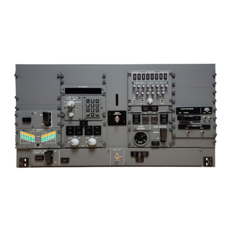
Opencockpits B737 MAX AFT Overhead Installation & user manual
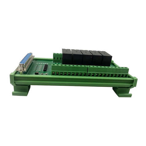
WEIHONG
WEIHONG PM53B Manufacturer's manual

J.R. Clancy
J.R. Clancy SceneControl 500 operating manual
Vaillant
Vaillant VRC 700/6 operating instructions
Balboa Instruments
Balboa Instruments GS520DZ manual

