©2010 The Chamberlain Group, Inc.
01-35926 All Rights Reserved
FEATURES AND FUNCTIONS
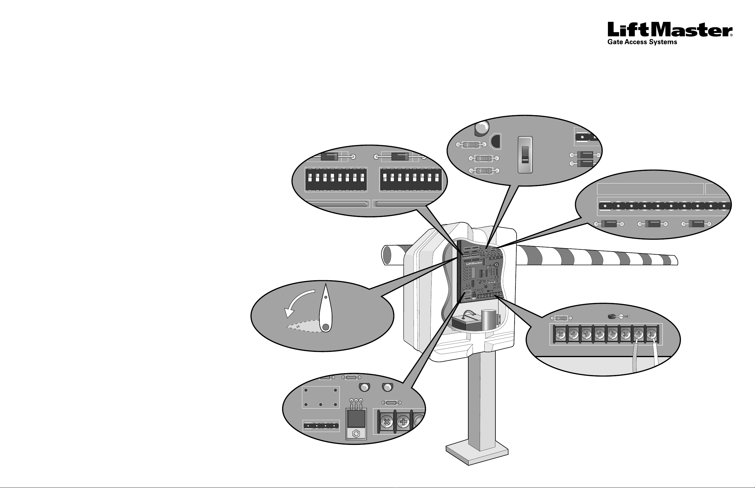
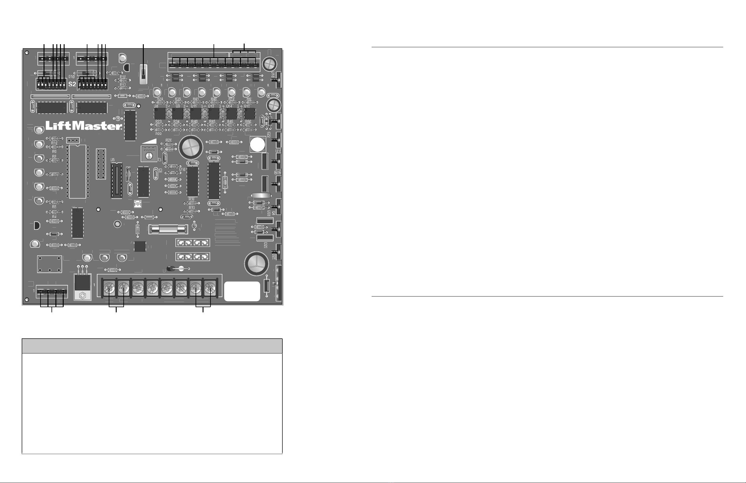
CONTROL BOARD LAYOUT
PROGRAMMING INPUTS
S2 DIP SWITCHES
TIMER-TO-CLOSE
DIP Switch S2-1 to S2-5
The S2-1 to S2-5 DIP switches will set the period of time the gate remains opened after reaching the
OPEN position.
Each DIP switch represents the number of seconds the gate will remain OPEN before CLOSING. With the
S2-3 DIP switch in the ON (factory default) position, there are 4 seconds to allow a vehicle enough time to
move out of the path of the closing barrier arm.
Turning multiple switches ON will combine the amount of time the barrier arm remains OPEN.
The maximum hold OPEN time is 32 seconds.
To de-activate this feature turn S2-7 DIP switch to the OFF position.
MULTIPLE VEHICLE MEMORY
DIP Switch S2-6
With S2-6 DIP switch in the ON position, the Multiple Vehicle Memory will activate, with inputs on terminal
4 and Common (COM) on the J5 terminal strip. Any of the terminals 9-12 on the J5 terminal strip can be
used for common.
NOTE: With Multiple Vehicle Memory activated, the barrier arm will remain OPEN until the
pre-authorized number of vehicles pass over the Close Loop.
AUTO CLOSE
DIP Switch S2-7
The S2-7 DIP switch (Auto Close) should be activated in case one or more of the pre-authorized vehicles
DO NOT pass through the gate. The barrier arm will close after the set amount of time elapses and the
count memory is reset to zero.
FAIL SAFE (AUTO OPEN ON AC POWER FAILURE)
DIP Switch S2-8
With S2-8 DIP switch in the ON position, the barrier arm will automatically OPEN approximately
15 seconds after a loss of power. Once the power has been restored the operator will resume normal
operation after any input.
With S2-8 DIP switch in the OFF position, the barrier arm will resume normal operation until the batteries
drop below 50% at which time the barrier arm will OPEN and remain opened until the batteries are fully
charged.
S1-DIP SWITCHES S2-DIP SWITCHES INPUT/OUTPUT LOCATIONS
ADIP Switches S1-1 to S1-4
FAST RUN TIMER FDIP Switches S2-1 to S2-5
TIMER-TO-CLOSE JS3 Manual Switch
BDIP Switch S1-5
SINGLE BUTTON FUNCTION GDIP Switch S2-6
MULTIPLE VEHICLE MEMORY KJ5 Wiring Inputs
CDIP Switch S1-6
CLUTCH OPTION HDIP Switch S2-7
AUTO CLOSE LJ5 Common (COM) Wiring Inputs
DDIP Switch S1-7
HANDING THE BARRIER ARM IDIP Switch S2-8
FAIL SAFE MK1 Relay (optional) and
Terminal Strip (J1)
EDIP Switch S1-8
K1 RELAY (OPTIONAL) NAccessory Output Power
(300 mA) max.
OMotor Wiring Connections
S1 DIP SWITCHES
FAST RUN TIMER (FULL SPEED RUN TIMER)
DIP Switch S1-1 to S1-4
When the gate operator activates, it ramps up and slows down for a xed amount of time, but will run at
full speed for variable amounts of time depending upon the settings of the S1-1 to S1-4 DIP switches.
Each DIP switch represents increments of 1/8 second.
When DIP switches S1-1, S1-2 and S1-3 are in the ON position, the Fast Run Timer is set to 2-3/8 seconds
by factory default.
When DIP switches S1-1 to S1-4 are set in the OFF position, the full speed run time is 1-1/2 seconds.
The longer the operator runs at full speed, the less ramp up and slow down time. When adjusting, make
sure the Fast Run Timer settings DO NOT overrun the slow down time.
SINGLE BUTTON FUNCTION
DIP Switch S1-5
With S1-5 DIP switch in the ON position, the Single Button Function (Command to Open/Command to
Close) will activate, with inputs on terminal 4 and Common (COM) on the J5 terminal strip. Any of the
terminals 9-12 on the J5 terminal strip can be used for common.
When using this feature with the radio receiver (provided), move the radio wire from terminal 1 to
terminal 4 on the J5 terminal strip.
CLUTCH OPTION
DIP Switch S1-6
With S1-6 DIP switch in the ON position, and using the Clutch Option; when the barrier arm is manually
forced UP (OPEN), the barrier arm will automatically CLOSE.
If the Close Loop detects tailgating, the K1 Relay will activate. If an anti-tailgating alarm is wired into
terminal strip (J1), an alarm will sound.
NOTE: When using the Clutch Option, turn DIP switches S1-6 and S2-7 to the ON position (Auto Close).
When this feature is activated the barrier arm will CLOSE by the timer whenever it is forced UP (OPEN).
HANDING THE BARRIER ARM
DIP Switch S1-7
The J4 Motor Wiring is controlled by DIP switch S1-7. The Handing of the Barrier Arm may be changed
from right-hand to left-hand operation by reversing the factory default motor connections.
NOTE: Right-hand or left-hand operation is determined by facing the control board with
the barrier arm in the CLOSED position. If the barrier arm is to the right, it is set for right-hand gate
operation.
1. For left-hand operation reverse the motor wires on J4-7 (blue wire) and J4-8 (orange wire)
(see illustration example "D" on reverse side).
2. Set DIP switch S1-7 to the ON position.
3. Turn the Limit Cam (see backside of control board) until the barrier arm is in the CLOSED position.
4. Turn the Limit Cam position 90 degrees to the left until the magnet is just behind the limit sensor
(see illustration example "F" on reverse side). The barrier arm will now be in the OPEN position.
5. Cycle the power and test the Handing of the Barrier Arm.
K1 RELAY (OPTIONAL)
DIP Switch S1-8
Auxiliary devices such as Counters, Alarms, Buzzers, and SAMS (Sequence Access Management System),
can be wired into the K1 Relay and terminal strip (J1).
When S1-8 DIP switch is in the OFF position, the K1 Relay will activate throughout the OPEN cycle.
When S1-8 DIP switch is in the ON position, the K1 Relay will be activated briey until the OPEN LIMIT
(OLS) is reached.
AD
E
B
C
FH
I
G
4VA
XFMR
+
BEAT BAT L
P
WER
N
Aux Relay
1
R13
A D
R
–
AT– M
+
T
OTOR
X LIMIT
1
2
M
2
T
5
7
PEN
D1
19
L
R
C
R1
D
L
E
D
L
PEN
D1
PEN
A
X
AFET
D1
L
E
D2
A
K
HAD
PE
LOS
MAN
A
8
12
P
R
T
T
7
15
2
F
1
C16
–
2
D
R1
1
R
+
R33
R5
X
R4
5
ARNING FO
NTIN
PR
TE
TI
N
A
AIN
T FIRE
REPLA
E
NLY
ITH THE
AME
TYPE AND RATIN
F FU
43
59
D
T
R5
13
R
A
ONM
L
FBCDE GHI J K