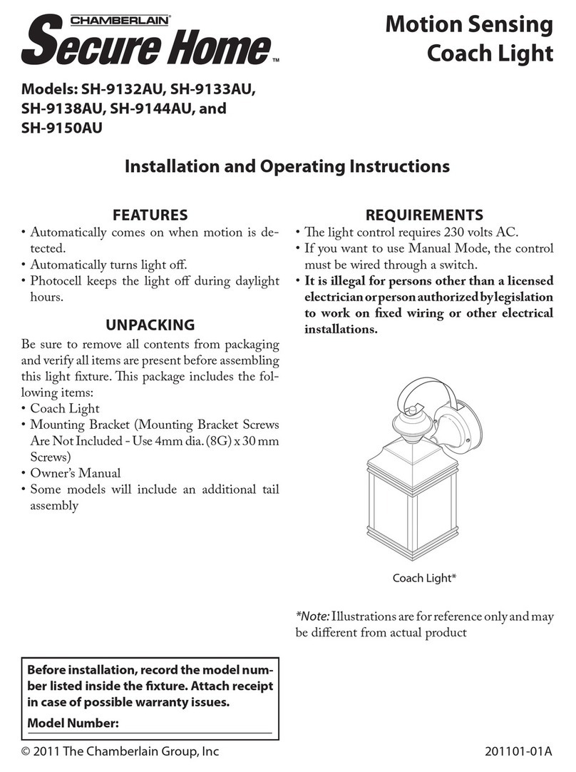
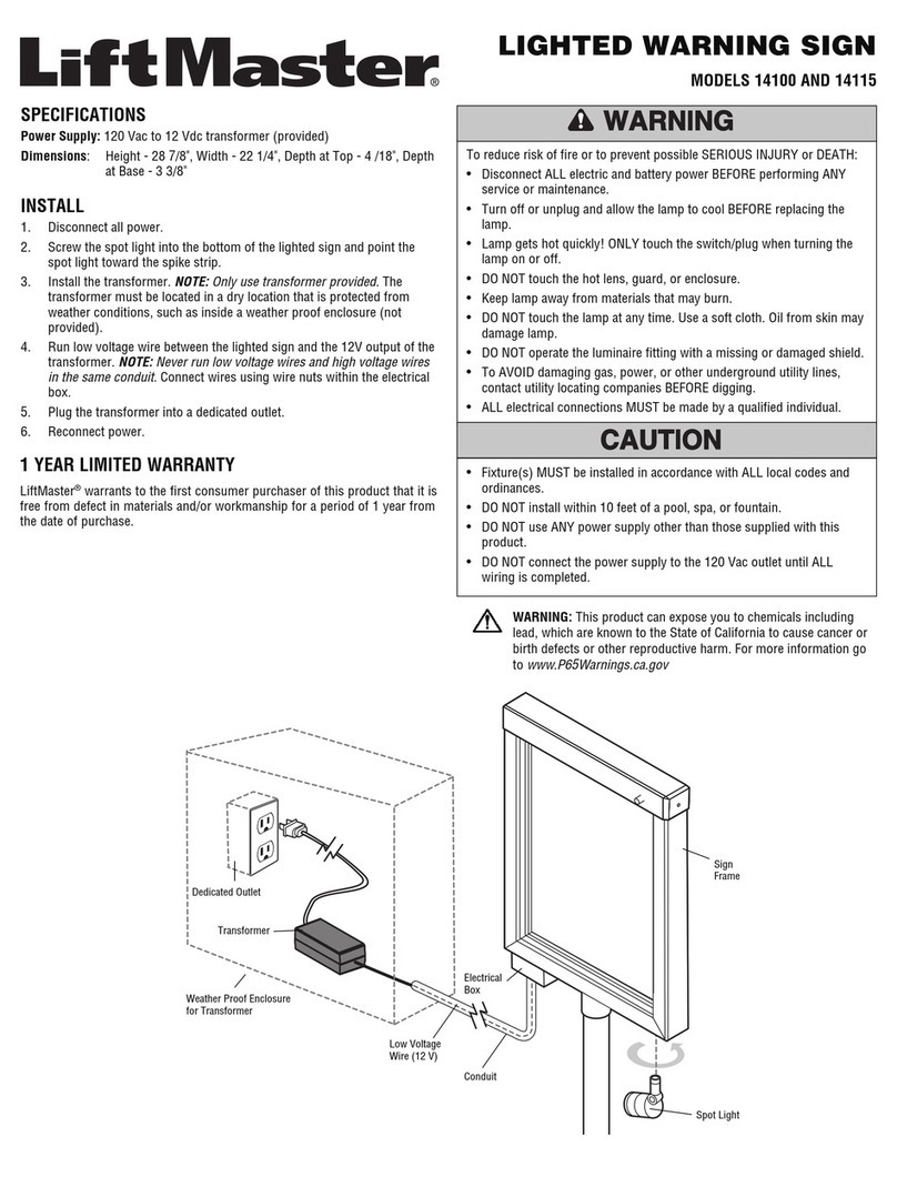
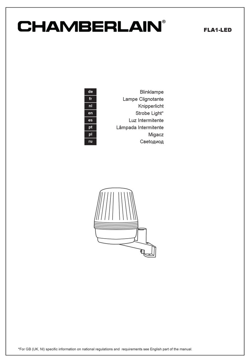
Chamberlain Secure Home SH-9392AU User manual

FEATURES
•Automaticallycomesonwhenmotionisde-
tected.
•Automaticallyturnslighto.
•Photocell keeps the light o during daylight
hours.
•Postorpedestalmount.
UNPACKING
Besuretoremoveallcontentsfrompackaging
andverifyallitemsarepresentbeforeassembling
thislightxture.ispackageincludesthefol-
lowingitems:
•LightFixture
•TopCover
•LensShields(x2)
•DecorativePedestalCover
•Owner’sManual
REQUIREMENTS
•elightcontrolrequires230voltsAC.
•Recommendedmountingheightforsensoris4
to7feetabovetheground.
•IfyouwanttouseManualMode,thecontrol
mustbewiredthroughaswitch.
•It is illegal for persons other than a licensed
electricianorpersonauthorizedbylegislation
to work on xed wiring or other electrical
installations.
Before installation, record the model num-
ber listed inside the xture. Attach receipt
in case of possible warranty issues.
Model Number:
© 2011 The Chamberlain Group, Inc 201104-01A
Lantern*
*Note:Illustrationsareforreferenceonlyandmay
bedierentfromactualproduct
Die-Cast Metal, Motion-
Activated Post Light
Installation and Operating Instructions
Model: SH-9392AU
®
TM

2201104-01
IMPORTANT SAFETY AND INSTALLATION INFORMATION
Beforeinstallingcoachlight,readallinstructionscarefullyandkeepowner’smanualforfuturerefer-
ence.
•
WARNING:Topreventelectricshock,pleaseensurethatpowerisdisconnectedbeforeinstallation.
•isxturemustbeconnectedtoa230V-240V~50Hzpowersource.
•exturemustbeproperlygrounded.
•isxtureisdesignedforoutdoorinstallationandshouldbemountedtoawall.
•Toachievebestresults,thisxtureshouldbemounted1.2to2.1meters(4to7feet)abovethe
ground.
•Donotusedimmerswitchesortimerswiththisxture.
esensoronthislightxturedetects“motion”bythemovementofheatacrossthecoveragearea.
However,followingareexamplesofobjectsthatalsoproduceheatandcancausethesensortotrigger:
•PoolsofWater •AirConditioners
•DryerVents •Animals
•HeatingVents •AutomobileTrac
Ifyoususpectthataheatsourceofthistypeistriggeringthesensor,reducethesensitivity.
esensoronthisxtureismoresensitivetothemovementofheatmovingacrossthecoveragearea
andlesssensitivetothemovementofheatdirectlytowardsit.
Least Sensitive Most Sensitive
Sensor
Motion Motion

3
201104-01
INSTALLATION
This light xture must be installed by a
licensed electrician or other person autho-
rized by legislation to work on xed wiring
or other electrical installations.
IMPORTANT: Do NOT use with dimmers or
timers.
Forbestperformance,mountthextureabout1.2
to2.1meters(4to7feet)abovetheground.
Note:Werecommendhavinganassistanthelphold
thelightassemblyduringthewiringprocess.
WARNING: Turn power o at circuit
breaker or fuse. Place tape over circuit
breaker switch and verify power is o at
the xture.
CAUTION: Light xture must be mount-
ed above a non-ammable surface.
PEDESTAL MOUNT
Ifmountingonapedestal,a76mm(3")diameter
pedestalbaseorpost(notsupplied)isrequired.
Beforewiring,slidepedestalcover(supplied)onto
pedestalbaseorpost.Seeillustrationsbelow.
Pedestal Mount with Pedestal Base
Sensor Assembly
Pedestal Cover
Pedestal Base
and Screws
(Not Suppled)
Junction Box
Pedestal Mount with Pedestal Post
Sensor Assembly
Pedestal Cover
Pedestal Post

4201104-01
TEST
MINUTES
SENSITIVITY
AUTO
LO
M
HI
1
5
10
2.
InstallaE27screwbaselightbulbintosocket.Do
not exceed wattage rating on xture label.
Note:Donotscrewsensorassemblyontolight
postuntilaftercompletingthestepsunderTesting
and Adjustments.
Terminal Block
IMPORTANT:
Terminal
block cover must
be used to insulate
terminal block.
From Fixture From AC Source
WIRING
1. Connectthexturewirestotheterminalblock
accordingtodiagram.Makesureallscrewson
terminalblockaretightenedsecurely.
WARNING: Turn power o at circuit
breaker or fuse. Place tape over circuit
breaker switch and verify power is o at
the xture.
Green/YellowGreen/Yellow
Blue Blue or Black
Brow
nR
ed or Brown
Figure 1
Figure 2
Figure 3
TESTING AND ADJUSTMENTS
1. Turn on the circuit breaker and light
switch.
Note:Sensorhasa11/2minutewarmupperiod
beforeitwilldetectmotion.Whenrstturned
onwait11/2minutes.
2. Set:
ON-TIMEswitchtoTEST
SENSITIVITYswitchto“M”(midway)
TEST
MINUTES
SENSITIVITY
AUTO
LO
M
HI
1
5
10
3. Placethesensorassemblysnuglyontolight
postensuringthatwiresarenotpinched.
4.
Walkthroughthecoverageareanotingwhere
youarewhenthelightsturnon.InTESTmode,
light will stay on for 5 seconds after sensing
motionandthenturno.
Note:
Removesensorassemblyfromlightpost
tomakeadjustmentsasneeded.

5
201104-01
Maximum
Maximum Range Coverage Angle*
(Side View) (Top View)
5. Adjust the SENSITIVITY to increase or
decreasetherangeasneeded.Toomuchsen-
sitivitymaycausefalsetriggeringduetoheat
sourcesinthecoveragearea(seeAdjustment
of Coverage AreaorTroubleshootingsection).
6. SettheamountofON-TIMEyouwantthe
lighttostayonaftermotionisdetected(1,5,
or10minutes).etimerwillresetaslong
asthereismotionpresent.Oncemotionhas
stopped, the timer will time-out after the
selectedamountoftime.
360°
9.1 m (30 ft.) in
all Directions
*Withoutlensshieldinstalled.
Sensor Height
1.5 m (5 ft.)
Note:Whenrstturnedonwaitabout11/2minutes
forthecircuitrytocalibrate.
*resetstoAutoModeatdawn.
OPERATION
MANUAL MODE
... back on.
1 Second
OFF then...
Manual mode only works at
night because daylight returns
thesensortoAUTO.
Flipthelightswitchoforone
second then back on to toggle
betweenAUTOandMANUAL
MODE.
Manualmodeworksonlywith
theON-TIMEswitchinthe1,
5,or10position.
MANUAL MODE
AUTO
TEST
ON-TIME Switch at 1, 5,
or 10 minutes
MODE SWITCHING SUMMARY
Flip light switch
o for one second
then back on*
*Ifyougetconfusedwhileswitchingmodes,turn
thepoweroforoneminute,thenbackon.After
thecalibrationtimethecontrolwillbeintheAUTO
mode.
Mode: On-Time Works: Day Night
Test 5Seconds x x
Auto 1,5,or10
Minutes x
Manual ToDawn* x

6201104-01
ADJUSTMENT OF COVERAGE AREA
esensoronthislightxturedetects“motion”
bythemovementofheat(bodyheat)acrossthe
coveragearea.However,followingareexamples
ofobjectsthatalsoproduceheatandcancause
thesensortofalsetrigger:
•PoolsofWater •AirConditioners
•DryerVents •Fenced-InAnimals
•HeatingVents •AutomobileTrac
Ifyoususpectthataheatsourceofthistypeis
falsely triggering the sensor and reducing the
sensitivitydoesnotsolvetheproblem,thenalens
shield(included)canbeinstalled.eplasticlens
shieldisdividedinto3sections.Eachsectionwill
reducethecoverageangleby30degrees.
1. Breakotheamountoflensshieldneededto
blockthedesiredareaofcoverage.
2. Snapplasticlensshieldontosensor.
3. Retesttoconrmthatthesensorisnolonger
falsetriggering.
Note:Tohelpdetermineamountoflensshield
required,applysmallsectionsoneatatime.Ad-
ditionalsectionscanbeappliedifnecessary.
Lens Shield
Sensor
Lens
90˚ Area
Blocked
Lens Shield
Eective Coverage
Area (Top View)
FINAL ASSEMBLY
1. Attachsensorassemblytopostusingthethree
screwssupplied.Tightenscrewssecurely.
2. Screw top cover onto top of xture. Hand
tightenonly.
Glass
Fixture
Top Cover
Light Bulb
Sensor
Assembly
Decorative
Screw (2)
Screw (3)
Figure 4

7
201104-01
SPECIFICATIONS
Range.................................................Upto9.1m(30ft.)[varieswithsurroundingtemperature]
SensingAngle.....................................Upto360°
ElectricalLoad...................................Seelabelonxtureformaximumwattagerating
BulbType...........................................E27ScrewBase,Type“A”
PowerRequirements...........................230VAC,50Hz
OperatingModes...............................TEST,AUTO,andMANUALMODE
ON-Timer..........................................1,5,10minutes
TestTimer..........................................5Seconds
ManualModeTimer..........................Dusk-to-Dawn
SYMPTOM POSSIBLE CAUSE SOLUTION
Lightwillnotcome
on.
1. Lightswitchisturnedo.
2. Bulbislooseorburnedout.
3. Fuseisblownorcircuitbreakeristurnedo.
4. Daylightturn-oisineect.
5. Incorrectcircuitwiring,ifthisisanewinstallation.
1. Turnlightswitchon.
2. Checkbulbandreplaceifnecessary.
3. Replacefuseorturncircuitbreakeron.
4. Recheckafterdark.
5. Verifywiringiscorrect.
Lightcomesonin
daylight.
1. Light control may be installed in a relatively dark
location.
2. LightcontrolisinTEST.
1. e xture is operating normally under these
conditions.
2. SetON-TIMEswitchto1,5,or10minutes.
Lightcomesonfor
noapparentreason.
1. Lightcontrolmaybesensingsmallanimalsorautomobile
trac.
2. Sensitivityissettoohigh.
1. Reducesensitivity.
2. Reducesensitivity.
Lightstayson
continuously.
1. esensormaybepickingupaheatsourcelikeanair
vent, dryer vent, or brightly painted, heat-reective
surface.
2. LightcontrolisinManualmode.
3. Sensitivityissettoohigh.
1. Reducesensitivity.
2. SwitchtoAuto.
3. Reducesensitivity.
Lightasheson
ando.
1. LightcontrolisintheTESTmodeandwarmingup.
2. Heatbeingreectedfromotherobjectsmaybeaecting
thesensor.
1. Flashingisnormalundertheseconditions.
2. Re-aimsensor.Reducesensitivity.
TROUBLESHOOTING GUIDE
eChamberlainGroupreservestherighttodiscontinueproductsandtochangespecicationsat
anytimewithoutincurringanyobligationtoincorporatenewfeaturesinproductspreviouslysold.

8201104-01
CHAMBERLAIN LIMITED WARRANTY
Lighting and Chime Products
ChamberlainAustraliaPtyLimited/Chamberlain NewZealandLimited(Chamberlain)is committed tomanufacturingandsupplyinghighquality goods. As
partofthiscommitment,weseektoprovidereliableserviceandsupportforourgoodsandarepleasedtoprovideyou,theoriginalpurchaser,withthisChamberlain
LimitedWarranty.
WealsoprovidethefollowingstatementasrequiredbytheAustralianConsumerLaw:InAustralia,inadditiontoyourrightsunderthisChamberlainLimitedWar-
ranty,ourgoodscomewithguaranteesthatcannotbeexcludedundertheAustralianConsumerLaw.Youareentitledtoareplacementorrefundforamajorfailureand
forcompensationforanyotherreasonablyforeseeablelossordamage.Youarealsoentitledtohavethegoodsrepairedorreplacedifthegoodsfailtobeofacceptable
qualityandthefailuredoesnotamounttoamajorfailure.
Chamberlain’s warranty
Chamberlainwarrantstotheoriginalpurchaserofthelightingorchimeproduct(includinganyLEDlightswhichareprovidedbyChamberlainaspartofthegoods)
(Unit)thattheUnitisfreefromdefectsinmaterialsandworkmanshipforaperiodof12monthsfromthedateofpurchase.
DuringtheapplicableChamberlainLimitedWarrantyperiod,ifyouareconcernedthattheUnitmaybedefective,contactyourretailerwhowillprovideyouwitha
replacementUnitorreferyoutoourservicecentreforafactoryrepairorreplacement.
Ifyourretailerrefersyoutous,callourservicecentreonthetollfreenumberbelowandaChamberlaintechnicianwilldiagnosetheproblem.Oncetheproblemhas
beendiagnosed,subjecttoyourrightsundertheAustralianConsumerLawwithrespecttomajorfailures,Chamberlainwillprovideyouwithshippinginstructions
forafactoryrepairorreplacement.
Ifafactoryrepairorreplacementisrequired,providedthedefectivepartorUnitisreturnedtoChamberlainwell-packagedandinaccordancewithChamberlain’s
shippinginstructions,Chamberlainwillrepairor,atitsoptionbutsubjecttoyourrightsundertheAustralianConsumerLawwithrespecttomajorfailures,replace
anydefectivepartorUnitandreturnittoyouatnocost.
RepairsandreplacementpartsprovidedunderthisChamberlainLimitedWarrantyareprovidedfreeofchargeandarewarrantedfortheremainingportionofthe
originalwarrantyperiod.
isChamberlainLimitedWarrantyprovidesbenetswhichareinadditiontoyourotherrightsandremediesasaconsumer.
Exclusions
Ifourservicecentredeterminesthatawarrantyclaimhasbeenmadeinrespectofafailureordefectarisingunderoroutofanyexclusiondetailedbelowsuchthatthe
claimisnotcoveredunderthisChamberlainLimitedWarranty,wemay,subjecttoyourotherrightsandremediesasaconsumer,chargeyouafeetorepair,replace
and/orreturntheUnittoyou.
Exclusions
isChamberlainLimitedWarrantydoesnotcoveranyfailureof,ordefectin,theUnitdueto:
1. non-compliancewiththeinstructionsregardinginstallation,operation,maintenanceandtestingoftheUnitorofanyproductwithwhichtheUnitisused;
2. anyattemptbyapersonotherthananauthorisedinstallertorepair,dismantle,reinstallormovetheUnittoanotherlocationonceithasbeeninstalled;
3. tampering,neglect,abuse,wearandtear,accident,electricalstorm,excessiveuseorconditionsotherthannormaldomesticuse;
4. problemscausedbyelectricalfaultsorreplacementofbatteriesorlightbulbs;
5. submersioninwaterorotheruids;
6. powersupplygreaterorlessthanwhatisspecied;
7. useofalightbulbwithahigherwattagethanthatspecied;or
8. forchimesproducts,radiointerferencefromanotherradiofrequencyappliance.
IfthisChamberlainLimitedWarrantydoesnotapply,youmayhaverightsavailabletoyouundertheAustralianConsumerLaw.
Liability – Australia only
ExceptassetoutintheAustralianConsumerLaw(beingSchedule2ofthe
Competition and Consumer Act 2010
)(asamended,consolidatedorreplaced):
1. allotherguarantees,warrantiesandrepresentationsinrelationtotheUnitoritssupplyareexcludedtotheextentthatChamberlaincanlawfullyexcludethem;
and
2. undernocircumstanceswillChamberlainbeliableforconsequential,incidentalorspecialdamagesarisinginconnectionwiththeuse,orinabilitytouse,theUnit,
otherthanthosewhichwerereasonablyforeseeableasliabletoresultfromthefailure.
Liability – New Zealand only
Exceptassetoutinthe
Fair Trading Act 1986
andthe
Consumer Guarantees Act 1993
(asamended,consolidatedorreplaced):
1. allotherguarantees,warrantiesandrepresentationsinrelationtotheUnitoritssupplyareexcludedtotheextentthatChamberlaincanlawfullyexcludethem;
and
2. undernocircumstanceswillChamberlainbeliableforconsequential,incidentalorspecialdamagesarisinginconnectionwiththeuse,orinabilitytouse,theUnit,
otherthanthosewhichwerereasonablyforeseeableasliabletoresultfromthefailure.
Note
Werequestthatyouretainyoursalesdocketorinvoiceasproof-of-purchaseandattachittothismanualtoenableyoutoestablishthedateofpurchaseintheunlikely
eventofawarrantyservicebeingrequired.ChamberlainreservestherighttochangethedesignandspecicationsoftheUnitwithoutpriornotication.Somefeatures
oraccessoriesoftheUnitmaynotbeavailableincertainmarketsorareas.Pleasecheckwithyourretailer.
Chamberlain service centre contact details
Australia New Zealand
Phonetollfree1800638234 Aucklandphone094772823
Faxtollfree1800888121 Phonetollfree0800653667
Email:customerser[email protected] Faxtollfree0800653663
Chamberlain Australia Pty. Ltd. Chamberlain New Zealand Limited
Unit 3, 7-9 Orion Rd 17A Arrenway Drive, Albany
Lane Cove NSW 2066 Auckland
(P.O. Box 1446, Lane Cove, NSW 1595) (PO Box 100221 North Shore 0745)
Website
www.chamberlainanz.com
Table of contents
Other Chamberlain Light Fixture manuals
Popular Light Fixture manuals by other brands

FRIEDHELM LOH
FRIEDHELM LOH RITTAL SZ 2500.200 Assembly and operating instructions

Atlantic
Atlantic SOLWPL3 product manual

SEBSON
SEBSON SET 3 R UNDER user manual

DOMUS LINE
DOMUS LINE K-PAD TWA installation manual

Cooper Lighting
Cooper Lighting Corelite Traverse Wall 1T5HO Specifications

Emos
Emos CLASSIC ZY1431T manual