Chamberlain 912GA User manual

1
N
E
W
S
CARTON INVENTORY
Verify carton inventory below.
The model 912GA is compatible with Chamberlain®Gate Access
Systems GA400D and GA420D. This kit replaces the AC plug-in
supply that is provided with the system.
COMPLETED OVERVIEW
BEFORE STARTING
Make sure the gate operator’s control box has two 12V 7AH batteries installed.
NOTE: The GA400D comes with a single battery. A second battery and battery cable can be obtained by
purchasing the 922GA battery kit.
10 WATT SOLAR PANEL
MODEL 912GA
Cable
Cable Ties (3)
Compass
Washered nuts (2) Bolt M6 x1 (2) Screw #14 x1 (2)
Solar Panel
Solar Panel
Mounting Bracket
Solar Panel
(Facing South)
Control Box
To reduce the risk of fire and the risk of SEVERE INJURY or DEATH to
persons disconnect electrical power to operator BEFORE proceeding.
ATTENTION
AVERTISSEMENT AVERTISSEMENT
AVERTISSEMENT
WARNING
CAUTION
WARNING
WARNINGWARNING
PRECAUCIÓN ADVERTENCIA
ADVERTENCIAADVERTENCIA

2
CYCLES/DAY USING 10W SOLAR PANEL
Gate Configuration
Single Gate < 300 lbs.
Single Gate > 300 lbs. or
Dual Gate < 300 lbs. Each
Dual Gate > 300 lbs. Each
Zone 1
52
26
17
Zone 2
32
16
11
Zone 3
13
6
4
1
1
1
2
3
REGIONAL INSTALLATION RECOMMENDATIONS
The solar map (above) and cycles/day ratings are approximations and do not account for installed accessories that draw additional battery power.
Ratings vary based on gate construction and installation. They are also shown for using a single 10W solar panel in conjunction with two 12 Volt 7.0
AH batteries. Ratings will improve by adding additional 10W solar panels. If required, up to three 10W panels (30W total) can be wired in parallel to
increase the number of cycles per day.
NOTE: The solar panel(s) recommendation is based upon the average solar radiation and the temperature effects on batteries in the given regions.
Local geography and weather conditions may require additional solar panels. Solar panels cannot be installed in areas that experience heavy fog or
lake effect rain and snow.
PREPARATION
SelectSite forSolarPanel(s)
The solarpanel(s) mustbe located in an open area clearof obstructions and shading forthe entire day.
NOTE: The solar panel(s) comes with a 10' cable. If a location near the control box cannot be found, an additional cable will be required.
(Model 917GA). Northern climates (where temperatures reach -4°F(-20°C) and below) are poor candidates for battery powered gate operator
applications. This also makes them poor candidates for solar power. Call technical support for more information.
NOT RECOMMENDED

3
INSTALLATION
Position SolarPanel(s)
NOTE: If the panel(s) is not casting a shadow, the battery is not being charged.
The location of the panel(s) is critical to the success of the installation. In general, the panel(s) should be mounted using the provided angle bracket
facing DUE SOUTH. The solar panel(s) should be mounted in an area clear of all obstructions and shading from buildings and trees. The area should
be clear for a 180° arc from due east of the panel(s) location to due west of the panel(s) location.
NOTE: Tall trees or buildings that do not shade the solar panel(s) in the summer could shade the solar panel(s) during the winter months when the
sun sits lower in the sky.
TIP: Wire runs should be kept as short as possible. The solar panel(s)
can be located up to 100' from the operator using #16 AWG wire in any
direction, including elevating it. If a suitable site cannot be found for the
panel(s), please contact Chamberlain to determine if solar is appropriate
for this installation.
Winter Sun Height
South
Up to 15°
Summer Sun Height
TIP: To optimize the system for winter
operation the angle can be increased an
additional 15° (solar panel(s) sits more
vertical).
TIP: The area around the solar panel(s) should be
clear of shadows or obstructions to the sun for a 180°
arc east to west.
INCORRECT
CORRECT
NOTE: DO NOT install solar panel near potential
shading or obstructions that will block the panel
during any part of the day.
South
Solar Panel
Sun’s Position
South
180°

4
Insert Mounting Bolts
Insert two bolts into the track located on the back of the solar panel(s).
Mounting
Surface
Angled Bracket Must
Face DUE SOUTH
Mounting
Surface
Angled Bracket Must
Face DUE SOUTH
Bolt
Bolt Hole
Track
Bolt
Bolt Hole
Track
Solar Panel
Slide bolts in track away from bolt
hole and align both bolts
Secure SolarPanel(s) to SolarBracket
Secure solar panel(s) to solar bracket using two washered nuts.
Solar Panel
Washered Nut
Solar Bracket
Washered Nut
MountSolarPanel(s) Assembly
Secure solar panel(s) assembly to mounting surface using appropriate hardware.
Position SolarBracket
Position solar bracket on mounting surface. Mark and drill holes.
NOTE: Solar panel(s) MUST be installed facing south. Use a compass to determine direction.
Mounted Panel Must
Face SOUTH
Mounting
Surface

5
ConnectSolarPanel(s) to OperatorControl Box
Open the control box cover. Disconnect all power and batteries from the control board. Run the solar panel cable to the bottom of the control box.
Thread the cable through the watertight connector and pull the cable through until it reaches the AC PWR/SOLAR connector on the control board.
Tighten the watertight connector on the cable. Attach the solar panel wires to AC PWR/SOLAR input terminal (polarity is not important). Leave the AC
PWR/SOLAR earth ground connection open.
NOTE: The system is designed to run off either the AC PWR/SOLAR plug-in power adapter (provided with the system) or a separate solar panel, but
not both. The AC Plug-in power adapter wires must be removed before the solar panel wires can be connected.
Connect the AC PWR/SOLAR connector to the control board. With the batteries still disconnected, the control board should power up if the solar panel
is correctly installed and the sun is shining. This is observed by the DIAGNOSTIC LED blinking.
NOTE: If the sky is too overcast to allow the solar panel to power up the system, the panel will need to be verified at another time when the sun is
shining. There is no other way to verify the panel installation.
Reconnect the batteries and verify that the operator and all safety devices work correctly. Use the cable ties to secure the solar panel cable away from
places where it could be damaged. Make sure the rubber seal around the cover is intact and close the cover. Insert the four screws for the control box
cover.
AC PWR/
SOLAR
J4
Control Board
Red Black
Solar Panel
POWER WIRING

Operatordoes notpowerup when solar
panel is connected.
1. Too cloudy ordark. There may not be enough sunlight to power up the operator. If the solar panel is
not casting a shadow, there is not enough sunlight to power the operator.
2. Solarpanel is obstructed. Check the orientation and position of the solar panel to make sure it is
facing south. Make sure the glass of the panel is clean and free of debris.
3. Wire disconnected. Recheck the wiring and make sure that the panel is connected to AC PWR/
SOLAR. If multiple panels are used, make sure they are wired up in parallel with red wires connected
to red wires and black wires connected to black wires.
Operatorpowers up butdoes notrun
properly.
1. Batteries are notconnected. The system requires the batteries to run. Make sure that the batteries
are connected both at the batteries and at the control board.
2. Batteries are low. Make sure that the batteries are fully charged. It may require a full day of bright
sunlight to recover discharged batteries with the solar panel.
3. Obstruction sensed. Make sure that all safety inputs are clear (LED is not lit) and the stop input is
connected (STOP LED is lit) when the operator tries to run. Make sure that no cables or other
obstructions are preventing the gate(s) from moving freely.
Operatorworks fine forseveral weeks
ormonths butthen batteries die.
1. Batteries notbeing charged. Make sure the solar panel is facing south and free of all obstructions
throughout the day. Make sure the panel is clean of debris and connected correctly to the control
board.
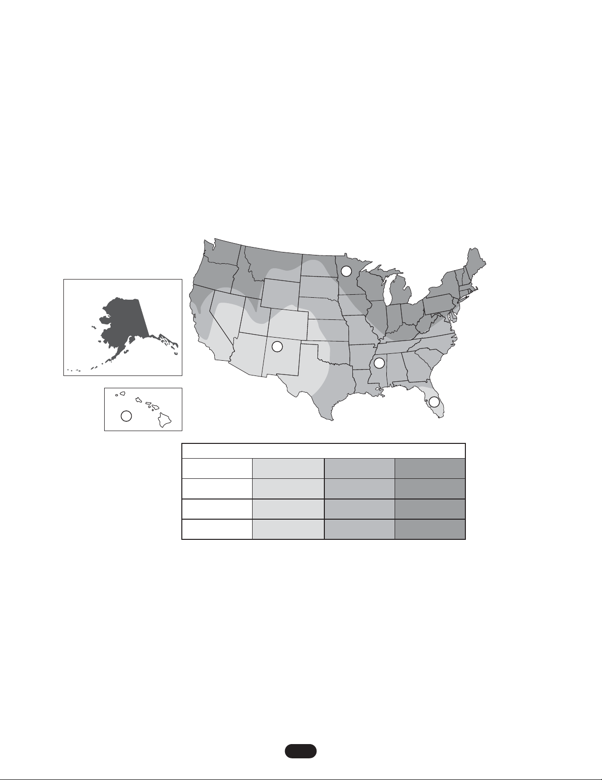
2. Operatoris overused. Consult the cycles/day chart to determine if the operator is being over
cycled based on the number of solar panels being used. It may be necessary to add a second panel.
3. Batteries are old. As batteries age, their ability to store energy decreases. Batteries typically must
be changed every 3 to 5 years, depending on usage, temperature, and other factors.
PROBLEM SOLUTION
6
TROUBLESHOOTING
NOTE: Take these steps if any of the components of the solar kit or the gate operator fail to operate properly.
MAINTENANCE
The glass of the solar panel(s) should be cleaned monthly to keep the panels operating at peak performance. Debris or dirt on the surface will
diminish or completely obstruct the panels’ ability to charge the operator.
NOTE: If panel(s) become damaged in any way, they must be replaced.
Wiring Multiple Panels
When multiple panels are required, they should be wired in parallel as shown below.
AC PWR/
SOLAR
J4
Red
Black
FOR TECHNICAL SUPPORT CALL OUR TOLL FREE NUMBER: 1-866-826-4943

7

© 2008, The Chamberlain Group, Inc.
01-33936B All Rights Reserved
Table of contents
Other Chamberlain Solar Panel manuals