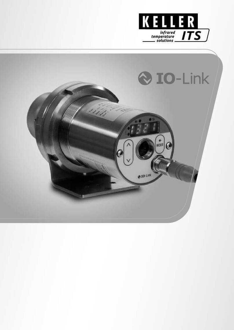
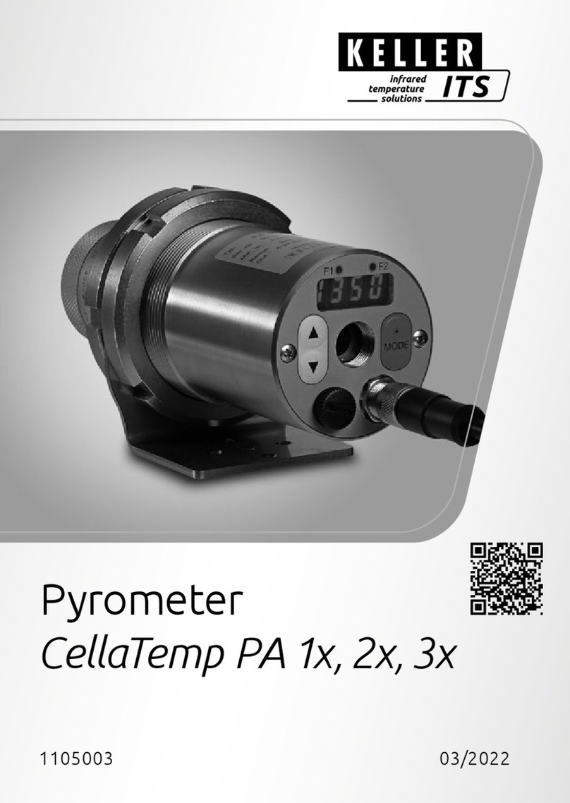
ITS Telecom PA 4 Series User manual

Operating manual PA 4x, 5x, 6x
Pyrometer CellaTemp
PA 4x, 5x, 6x
Mat. No.: 101 3032 01/2023

Operating manual PA 4x, 5x, 6x
Copyright prohibits the reproduction or distribution of this instruction
manual, including text, photographs or images contained herein, in
whole or in part, for any purpose whatsoever, without prior consent of
the author. This applies to any form of mechanical or electronic repro-
duction as well as to electronic transmission in any form through any
medium.
Please note:
Unless otherwise stated in this instruction manual, the instruments
described herein are subject to change without prior notice, particularly
modifications for the sake of technological advancement.
2010 KELLER HCW GmbH
Carl-Keller-Straße 2 - 10
D-49479 Ibbenbüren
Germany
www.keller.de/its/
830-hm / 810-het
PA4x_5x_6x_en.doc
26.01.2023

Operating manual PA 4x, 5x, 6x
Contents
1Miscellaneous ...................................................................................... 1
1.1 Information about this manual....................................................................................1
1.2 Explanation of symbols ..............................................................................................1
1.3 Liability and Warranty.................................................................................................1
1.4 Copyright....................................................................................................................2
2Safety....................................................................................................2
2.1 Intended use...............................................................................................................2
2.2 User’s responsibility ...................................................................................................3
2.3 Safety requirements...................................................................................................3
2.4 Electromagnetic Compatibility....................................................................................3
2.5 Quality Management Certification..............................................................................3
2.6 Environmental Management.......................................................................................3
3General Description.............................................................................4
3.1 Operating Controls and Display .................................................................................6
4Quick Reference Guide .......................................................................7
4.1 PA Connector Pin Assignment...................................................................................7
4.2 Power Requirement 24 V DC.....................................................................................8
4.3 Current Outputs 0/4 - 20mA.......................................................................................8
4.4 Switching output.........................................................................................................9
5Getting Started................................................................................... 10
5.1 General installation tips............................................................................................10
5.2 Pyrometer Alignment to Target ................................................................................10
5.3 Pyrometers with laser sighting .................................................................................11
5.4 Safety instructions and precautions .........................................................................11
5.4.1 Laser Radiation Hazard............................................................................................11
5.4.2 Laser Power.............................................................................................................12
5.4.3 Laser Warning Label................................................................................................12
5.4.4 Laser warning label must be visible!........................................................................13
5.5 Pyrometer with camera ............................................................................................13
5.6 Setting parameters at the pyrometer (basic configuration)......................................13
5.7 Setting Emissivity (Spectral mode)...........................................................................14
5.8 Setting the Emissivity Ratio (two-colour/ratio mode)................................................15
5.9 Adjusting the soot factor (Flame temperature measurement) .................................15
5.10 Parameterisation PA 69 with EERC algorithm.........................................................16
5.10.1 Commissioning the EERC algorithm........................................................................16
5.11 Output current range................................................................................................18
5.12 Simulated current signal for functional testing .........................................................18
6Functioning of the pyrometer........................................................... 19
6.1 Internal signal processing.........................................................................................19
7Configuration and Setup................................................................... 20
7.1 Signal Conditioning ..................................................................................................20
7.1.1 Emissivity and Transmittance (Spectral mode)........................................................20
7.1.2 Ambient Temperature Compensation (Spectral mode) ...........................................20
7.1.3 Dirt Alert (two-colour/ratio mode).............................................................................21
7.1.4 Temperature offset using linear interpolation...........................................................22
7.1.5 Signal Smoothing Filter............................................................................................23
7.1.6 Min/Max Data...........................................................................................................23
7.2 I/O Configuration......................................................................................................28
7.2.1 Selectable current output range...............................................................................28
7.2.2 Digital outputs...........................................................................................................29
7.2.3 Function „Level“........................................................................................................31
7.2.4 “Range” Function......................................................................................................32
7.3 Digital inputs.............................................................................................................33
7.3.1Analogue input for emissivity correction or ambient temperature compensation
(spectral mode).......................................................................................................................33
7.3.2 Analogue input to control emissivity ratio (two-colour/ratio mode)...........................34
7.4 General functions (configuration layer C011).....................................................34
Operating manual PA 4x, 5x, 6x
7.4.1 Green Status LED....................................................................................................34

7.4.2Activate Laser...........................................................................................................34
7.4.3 Video camera settings..............................................................................................35
7.5 Simulate current signals for analogue output Ao1 and Ao2 (configuration layer:
C100).................................................................................................................................35
8Setting Parameters at the device ..................................................... 36
8.1 Configuration level....................................................................................................36
8.1.1 Temperature measurement two-colour/ratio mode (Configuration layer: C001)36
8.1.2 Temperature measurement one-colour/spectral channel (configuration layer:
C002/C003) .................................................................................................................38
8.1.3 Configuration I/O (configuration layer: C010).....................................................39
8.1.4 General Functions (configuration layer: C011)...................................................42
8.1.5 Displayed temperature readings ..............................................................................43
8.1.6 Simulated current signal for outputs Ao1 and Ao2...................................................43
9CellaView software ............................................................................ 44
10 Installation of the USB driver............................................................44
11 How to operate the pyrometer with the CellaView software.......... 45
11.1 CellaView via USB point-to-point connection...........................................................45
11.2 CellaView via RS485 point-to-point connection .......................................................45
11.3 CellaView via RS485 bus connection.......................................................................47
11.4 Termination of RS485 bus .......................................................................................49
12 Operation of the pyrometer via terminal program.......................... 50
12.1 Serial Data Transmission of Temperature Data.......................................................50
12.2 Terminal connection via USB...................................................................................52
12.3 Terminal connection via RS485...............................................................................52
13 User-defined calibration / scaling of the current output................ 54
13.1 Calibration/scaling via CellaView..............................................................................55
13.2 Calibration/scaling via terminal connection..............................................................55
14 Shielding and Grounding..................................................................57
14.1 Potential equalisation...............................................................................................57
15 Connectivity Examples...................................................................... 59
15.1 Connection to VK 02/A Cable...................................................................................59
15.2 Connection to DA 230 digital display unit.................................................................59
16 Theory of Non-Contact Temperature Measurements.....................60
16.1 Advantages of Non-Contact Temperature Measurement........................................60
16.2 Measurements at Black Bodies (Cavity Radiators)..................................................60
16.3 Measurements of Real Radiators.............................................................................61
16.4 Emissivity Coefficient Table PA (Spectral mode).....................................................62
17 Maintenance.......................................................................................63
17.1 Cleaning the pyrometer lens ....................................................................................63
18 Technical Data PA 40 AF 20.............................................................. 64
18.1 Field of View Diagram PA 40 AF 20.........................................................................65
19 Technical Data PA 40 (650 –1700 °C) .............................................. 66
19.1 Field of View Diagrams PA 40..................................................................................67
20 Technical Data PA 40 (750 –2400 °C) .............................................. 69
20.1 Field of View Diagrams PA 40 (750 –2400 °C).......................................................70
21 Technical Data PA 40 (850 –3000 °C) ............................................... 72
21.1 Field of View Diagrams PA 40 (850 –3000 °C)........................................................73
22 Technical Data PA 40 AF 18.............................................................. 75
22.1 Field of View Diagram PA 40 AF 18.........................................................................76
23 Technical Data PA 43 AF 20 (MR 600 -1400 °C)...............................77
23.1 Field of View Diagram PA 43 AF 20.........................................................................78
24 Technical Data PA 43 (MR 650 –1700 °C)........................................ 79

Operating manual PA 4x, 5x, 6x
24.1 Field of View Diagram (MR 650 –1700 °C)............................................................80
25 Technical Data PA 43 (MR 750 –3000 °C)........................................ 86
25.1 Field of View Diagram PA 43 (MR 750 –3000 °C) ..................................................87
26 Technical Data PA 43 AF 17/ 18........................................................ 93
26.1 Field of View Diagram PA 43 AF 17/ 18...................................................................94
27 Technical Data PA 44.........................................................................95
27.1 Field of View Diagram PA 44 ...................................................................................96
28 Technical Data PA 45......................................................................... 97
29 Field of View Diagrams PA 45........................................................... 98
30 Technical Data PA 47......................................................................... 99
30.1 Field of View Diagrams PA 47................................................................................100
31 Technical Data PA 50....................................................................... 101
31.1 Field of View Diagram PA 50 .................................................................................102
32 Technical Data PA 60....................................................................... 104
32.1 Field of View Diagrams PA 60................................................................................105
33 Technical Data PA 64....................................................................... 106
33.1 Field of View Diagram PA 64 .................................................................................107
34 Technical Data PA 69....................................................................... 109
34.1 Field of View Diagrams PA 69................................................................................110
35 Dimensions....................................................................................... 111
36 Technical data camera .................................................................... 112
37 Transmission values of protective glasses................................... 114
38 Accessories...................................................................................... 115
38.1 Mounting angle PA 11/K.........................................................................................115
38.2 Polarising filter........................................................................................................116
38.3 Mounting bracket PA 11/U .....................................................................................117
38.4 Quarz-window PA 20/I............................................................................................118
38.5 Cable VK 02/A........................................................................................................119
38.6 Cable VK 02/F........................................................................................................120
39 Mounting combinations .................................................................. 121
39.1 Mounting combination PA 20-007..........................................................................121
39.2 Mounting combination PA 20-010..........................................................................122
40 Glossary............................................................................................123
41 Shipping, Packaging and Disposal................................................124
41.1 Inspecting your shipment .......................................................................................124
41.2 Packaging...............................................................................................................124
41.3 Disposal of used apparatus....................................................................................124
42 Copyright.......................................................................................... 125
43 Default settings................................................................................ 126
43.1 Temperature measurement using two-colour/ratio mode (Configuration layer:
C001)...............................................................................................................................126
43.2 Temperature measurement using spectral mode (Configuration layer: C002,
C003)...............................................................................................................................127
43.3 Configuration I/O (configuration layer: C010)...................................................128
43.4 General Functions (configuration layer: C011).................................................129

Operating manual PA 4x, 5x, 6x

Operating manual PA 4x, 5x, 6x
1
1 Miscellaneous
1.1 Information about this manual
The purpose of the Operating Manual is to provide the user with all nec-
essary information to be able to install the pyrometer and any necessary
accessories.
Before starting installation, be sure to read and understand this entire
manual, in particular the chapter on safety! The instructions contained in
this manual, especially those concerning safety, as well as site-specific
regulations governing UV radiation must be complied with at all times!
1.2 Explanation of symbols
Important safety-related references in this manual are marked with a
symbol.
CAUTION!
This symbol indicates important information which, if neglected, might
result in pyrometer damage, malfunction or breakdown.
NOTE !
This symbol points out guidelines which should be followed for efficient
and trouble-free operation.
1.3 Liability and Warranty
All information compiled in this manual is in accordance with applicable
regulations. The statements made are based on state-of-the-art technol-
ogy and reflect our extensive knowledge and many years of experience.
NOTE !
Always carefully read this Operating Manual before beginning any
work on or with the instrument, especially prior to installation and
initial setup! The Manufacturer shall not be held liable for any
damages or malfunctions arising from a disregard of the warnings
and instructions contained herein.
This Operating Manual must be retained for future use. Please ensure
that all persons who wish to operate the instrument have access to this
manual.

Operating manual PA 4x, 5x, 6x
2
1.4 Copyright
This Operating Manual should be treated as confidential. It is solely in-
tended for use by persons involved with the instrument. This manual
may not be made available to a third party without prior Manufacturer’s
consent. Please contact the Manufacturer if the need should arise.
NOTE !
The data, texts, charts, drawings, images or other representations
contained in this manual are copyright-protected and furthermore,
subject to intellectual property rights. Violators will be prosecuted.
Unauthorised use and copyright infringement will be subject to
penalty by law.
Reproductions of any kind, in whole or in part, as well as the exploitation
or disclosure of this manual’s content without the explicit written approval
of the Manufacturer are expressly prohibited by law. Violations shall be
subject to compensation claims by the Manufacturer. The right to claim
additional indemnities remains reserved.
2 Safety
This chapter outlines all important safety aspects to be considered for
optimum employee protection and to ensure safe and reliable opera-
tions.
2.1 Intended use
The pyrometer is solely intended for non-contact measurement of tem-
peratures as described in this manual. Any other use is not intended.
Operational safety can only be ensured when the instrument is used for
its intended purpose.
CAUTION !
It is prohibited to use the pyrometer for any other purpose
beyond what is specified in this manual. Using the instru-
ment in any other manner will be considered as improper.
The manufacturer is only liable for damage that occurs during correct
use. The prerequisite for any liability, however, is that the cause of the
damage is due to a defective product and the defect in the product was
caused by the manufacturer.

Operating manual PA 4x, 5x, 6x
3
2.2 User’s responsibility
The pyrometer may only be used when it is in perfect working condition.
2.3 Safety requirements
The instrument works with an operating voltage of 24 VDC. The voltage re-
quired for operation must be supplied by a separate power supply. This
power supply unit must conform to directive DIN IEC 61010.
2.4 Electromagnetic Compatibility
The devices comply with the essential safety requirements of the Elec-
tromagnetic Compatibility Directive 2014/30/EU (EMC Act).
When connecting a power supply unit, make sure that is also conforms
to these standards. Radio interference may arise if the pyrometer is in-
terconnected with such peripheral devices which have not been properly
interference-suppressed. This may necessitate additional interference
suppression measures.
2.5 Quality Management Certification
The KELLER HCW Quality Management System meets the DIN EN ISO
9001 standards for design, production, repairs and service for non-
contact infrared temperature measuring equipment.
2.6 Environmental Management
Sustainable environmental management is more important than ever.
KELLER HCW’s corporate environmental management system complies
with DIN EN 14001/50001 standards.

Operating manual PA 4x, 5x, 6x
4
3 General Description
The two-colour pyrometer CellaTemp PA measures the intensity of infra-
red radiation at two different wavelengths. The ratio of these two intensi-
ties is proportional to the temperature. Thus a two-colour pyrometer
supplies a constant measurement signal even with weakened signals,
caused, for example, by vapour and dirt in the sighting path, condensed
optical lenses or changing surface properties of the target. These in-
struments serve a broad range of applications which include the iron and
steel producing industry as well as the metal, glass, cement and chemi-
cal industries.
Flame temperature measurement (only PA 47)
A key parameter for optimizing burnout and minimizing pollutant emis-
sions in incinerators is the knowledge of the combustion chamber tem-
perature, which can be determined in different ways. One of the possible
methods is the measurement of the flame temperature. The pyrometer
PA 47 detects the temperature of the soot particles in flames. The parti-
cle temperature of the flame is determined following the algorithm of
Rössler: from the black body temperature of the spectral measured val-
ue and the colour temperature of the two-colour measurement value.
This method has the advantage that the optical thickness of the flame
and the penetration depth of the pyrometer are taken into account.
To indicate the exact measurement spot, CellaTemp PA pyrometers fea-
ture through-the-lens sighting or, as an alternative, laser sighting or an
integrated camera.
The instruments have rugged stainless steel housings which make them
ideal for use in hostile industrial environments. PA pyrometers are
splash water proof according to IP65 (DIN 40050)
All PA pyrometers with through-the-lens sighting feature an interchange-
able, focusable lens. Through-the-lens sighting with target marker facili-
tates easy alignment to the target. PA instruments with laser sighting
feature an integrated laser which produces a laser dot image on the tar-
get object to indicate the precise measurement spot.
The adjustable emissivity factor makes it easy to adapt the pyrometer to
the specific radiation characteristics of the particular material measured.
All pyrometers of the PA series have two analogue current outputs; each
is switchable from 0 - 20 mA to 4 - 20 mA.
The output currents are linear to the measured temperature. The re-
quired temperature range can be set at the pyrometer.

Operating manual PA 4x, 5x, 6x
5
When ambient temperatures are higher than the admissible working
temperature, the output current is > 20.5 mA.
CellaTemp PA also features an analogue voltage input which can be
used as an alternative to current output 2. The emissivity factor or a cor-
rection for reflected ambient temperature can be controlled using this
voltage input.
Two serial interfaces (USB and RS485) are available. They enable the
user to change all operating parameters such as emissivity setting, tem-
perature range, smoothing function or output current range during run-
ning operations.
CellaTemp PA allows for continuous temperature data output in a user-
configured cycle time.

Operating manual PA 4x, 5x, 6x
6
3.1 Operating Controls and Display
The rear panel of the CellaTemp PA has a 4-digit display and 3 push-
buttons. The display shows the current temperature or, during configura-
tion using the push-buttons, the display will show the corresponding pa-
rameter.
Whenever the display shows a parameter, the F1 Parameter LED (yel-
low) will light up. The function of the F2 Status LED (green) is user-
configurable. In its initial state when supplied to the customer the F2
LED indicates current status for the switch able output Do1 as ready for
operation.

Operating manual PA 4x, 5x, 6x
7
4 Quick Reference Guide
4.1 PA Connector Pin Assignment
CAUTION!
The pyrometer housing is connected to the signal ground via a
0.1
F/50V capacitor. Isolate any unused wires in order to avoid
the display of erroneous data.
1 = white
2 = brown
3 = green
4 = yellow
5 = grey
6 = pink
7 = blue
8 = red
+ 24 V DC
Digital in- / output 1
Analogue output 2/ analogue input
Analogue output 1
Serial interface RS485 (A) (Tx-/D-)
Serial interface RS485 (B) (Tx+/D+)
Digital in- / output 2
GND
Shielding

Operating manual PA 4x, 5x, 6x
8
4.2 Power Requirement 24 V DC
The instrument works with an operating voltage of 24 V DC. The voltage
required for operation must be supplied by a separate power supply.
This power supply unit must conform to directive DIN IEC 61010.
The supply voltage is 135 mA for standard design, 150mA for models
with laser sighting and 175 mA for models with camera. CellaTemp PA
is equipped with inverse polarity protection. The output currents and
voltages share one ground connection via pin 8 of the connector.
A self-test is performed when the instrument is switched on. The display
will briefly indicate the software version and after that the emissivity set-
ting. When the self-test is completed the pyrometer is ready for opera-
tion and the display will show the current temperature reading.
NOTE !
In order to achieve a high degree of measurement accuracy and
repeatability it is important to allow the pyrometer time to warm
up. Turn the power supply on about 10 minutes, with camera 20
min before starting. We recommend that you protect the feed line
to the pyrometer against short circuit by using a 250 mA micro-
fuse.
4.3 Current Outputs 0/4 - 20mA
CellaTemp PA features two current outputs. Both of these outputs are
active current sources which supply linear output current. The user can
select between two scales: either 0 - 20 mA or 4 - 20 mA. Maximum load
is 500
.
The two current outputs are factory preset to 4 - 20 mA !

Operating manual PA 4x, 5x, 6x
9
For all pyrometers of the PA Series the current outputs are short-circuit-
proof and share one ground connection via pin 8 of the connector. Each
current output can be individually scaled and can be set either at the
display or via interface.
When only one current output is required, output 1 should be selected
(Pin 4)
4.4 Switching output
All pyrometers of the PA Series feature two switching outputs which can
be configured as digital outputs or digital inputs. The open collector out-
puts allow for a voltage of +24 V DC. For signal processing a pull-down
resistor can be applied to the ground connection of the supply voltage.
The maximum current of each open collector output is 30 mA.
VK 02/A
A
A
Ao2
Ao1
green
yellow
Load maximal 500 Ω
Ao1
Ao1

Operating manual PA 4x, 5x, 6x
10
See Chapter 7.2.2 for more information on configuration.
5 Getting Started
5.1 General installation tips
Install the pyrometer in a location where it will not be unnecessarily ex-
posed to smoke, ambient heat or water vapour.
A false reading (too low) will be displayed when the pyrometer lens is
dirty. Therefore, always ensure that the lens is clean.
The pyrometer’s optical path must remain unobstructed. Any interfer-
ence or obstacle may lead to measurement errors.
5.2 Pyrometer Alignment to Target
For accurate temperature measurement, it is essential that the py-
rometer is correctly aimed and focused on the target object. Make
sure that the optical path is not obscured because this would most
likely impair accuracy.
red
VK 02/A
Digital input 1
blue
brown
Digital input 2
Ground
PLC
+24 V
GND
51 KΩ
Imax = 30 mA
24 V DC
PA
brown
red
white
+ 24 V
bulb
relay

Operating manual PA 4x, 5x, 6x
11
When aiming the pyrometer with through-the-lens sighting to a target,
both the targeted object and the target marker (distinctly marked circled
spot in the viewfinder) must appear in sharp focus simultaneously. The
measured object must completely fill the target circle in the viewfinder.
A variable polarising filter is available to provide eye protection. This ac-
cessory can be screwed to the ocular lens to provide adjustable bright-
ness control.
If the actual target spot is the same size as the minimum spot size re-
quired by the distance-to-target ratio, or only marginally larger, then we
recommend that you check the maximum output current to verify proper
focussing.
5.3 Pyrometers with laser sighting
The pyrometer models PA xx AF xx /L feature a laser spot light which
can be activated to facilitate instrument alignment to the target spot.
Under normal operating conditions the laser will be off. To activate the
laser, press the MODE button on the rear panel for 2 seconds. Alterna-
tively, the laser can be switch on via switching input or PC. The laser will
automatically deactivate after 1- 15 minutes.
The pyrometer should be aimed and focused in such a way that—at the
proper distance to the target object—the laser beam produces razor-
sharp round dot to indicate the exact measurement spot.
For pyrometers featuring an integrated laser spot light, the light
may, when activated, influence the instrument’s temperature read-
ing. This influence will vary, depending on the instrument model
and the temperature. To ensure an accurate and reliable tempera-
ture reading, the laser spot light will automatically deactivate after
approximately 1- 15 minutes.The time is adjustable.
5.4 Safety instructions and precautions
The user must be familiar with following safety instructions.
5.4.1 Laser Radiation Hazard
Laser radiation can be harmful to the eye!
CellaTemp PA operates with a class 2 red light laser. Direct prolonged
viewing of a laser beam can injure the retina. Therefore, the following
safety precautions must be strictly observed, otherwise the laser may not
be operated!

Operating manual PA 4x, 5x, 6x
12
Only use the laser to align and focus the pyrometer. Deactive the
laser immediately afterwards. Alternatively, the laser will automat-
ically switch off after 1 - 15 minutes.
Never look directly into the laser beam path.
Do not leave the instrument unattended when the laser is activat-
ed.
Do not point the laser beam at any person.
During pyrometer installation and alignment, make sure to avoid
the possibility of laser light reflections caused by reflective surfac-
es.
All currently valid laser safety standards must be observed.
5.4.2 Laser Power
The laser operates at a wavelength of 630 - 680 nm (visible red light).
The emitted power of the laser beam at the lens opening is max. 1.0
mW. Under normal operating conditions, the emitted
radiation is not hazardous to human skin. This laser product is classified
according to laser class 2, EN60825-1, IEC60825-1.
5.4.3 Laser Warning Label
The black and yellow laser warning label is affixed next to nameplate of
the instrument. An arrow indicates the laser emission path (lens ope-
ning).
Fig. 5.2 Laser warning label affixed to the pyrometer

Operating manual PA 4x, 5x, 6x
13
5.4.4 Laser warning label must be visible!
If the pyrometer is installed within a machine or equipment in such a way
that the instrument’s warning label is visibly blocked, additional laser
warning labels (not included in scope of delivery) must be affixed to the
equipment or accessory in immediate vicinity to the laser beam emission
path opening.
5.5 Pyrometer with camera
The models PA xx AF xx /C features an integrated camera.
The video feed simplifies the optical alignment of the pyrometer and al-
lows a continuous observation of the measuring point.
When aiming the pyrometer focus the sensing head until the video im-
ages is sharp. (Technical data chapter 36)
5.6 Setting parameters at the pyrometer (basic configuration)
Use the buttons ▲▼ and the „MODE" button on the rear panel to ac-
cess and configure parameters. With these buttons you can view and
adjust all settings required for operating the pyrometer. (See Chap. 3.1).
Menu structure:
1. Press the MODE button while in normal operating mode to switch
to "configuration layer" mode.
2. Use ▲▼ to select the configuration layer for the parameter you
wish to set.
3. Press MODE to confirm. Press ▲▼ to select the particular pa-
rameter.
4. Press MODE to confirm. Press ▲▼ to adjust the parameter val-
ue.
5. Press MODE again to end. Press ▲▼ to select END/SAVE.
6. Now use MODE to either apply the changes you have made to
the settings [SAVE] or to close without saving these changes
Normal
operating mode
(temperature)
Select
config. layer
C000-
C999
Select
parameter
EPS
Adjust
parameter
99.9
MODE
MODE
MODE
▲▼
▲▼
▲▼

Operating manual PA 4x, 5x, 6x
14
[END] . After that, the display panel will resume showing the
temperature reading.
Parameter
configuration
layer
Explanation
EPS.Q
C001
Ratio correction (see chapter 5.8)
AO1._
C010
Lower limit of temperature span
analogue output Ao1(see chapter
5.11).
AO1.~
C010
Upper limit of temperature span
analogue output Ao1(see chapter
5.11).
AO1.4
C010
Hardware configuration of the ana-
logue output 0-20 mA, 4-20 mA
(see chapter 5.11).
AO1.T
C100
Temperature measurement simula-
tion to verify signal transmission
(see chapter 5.12).
NOTE !
Key lock may have been activated via interface. When selecting
the configuration layer you will be prompted to enter an access
code with P000. To obtain full access to parameter settings, enter
P100 otherwise you will only be able to view parameters but not
change them.
5.7 Setting Emissivity (Spectral mode)
A pyrometer measures temperature by detecting the radiant energy emit-
ted from an object’s surface in the form of electromagnetic waves. The
temperature reading not only depends on the intensity of the object’s
thermal radiation (how hot the object is), but also on the material’s par-
ticular surface characteristics and thus its specific ability to emit thermal
energy. This is called emissivity. To obtain an accurate temperature
reading, it is imperative that the pyrometer be adjusted for this emissivity
prior to measurement.
Set the emissivity correction at configuration layer C002/C003 .See
the Emissivity Coefficient Table in Chapter 12 to select the proper emis-
sivity factor for your application. We recommend that you first perform a
comparison temperature measurement with another device to determine
the correct emissivity factor for the task.
This manual suits for next models
15
Table of contents
Other ITS Telecom Measuring Instrument manuals

ITS Telecom
ITS Telecom 1RU8126MS User manual

ITS Telecom
ITS Telecom Ek PR PRO User manual

ITS Telecom
ITS Telecom H560 Dewpoint Pro User manual

ITS Telecom
ITS Telecom eXact Micro 20 User manual

ITS Telecom
ITS Telecom DD890 User manual

ITS Telecom
ITS Telecom Exact Micro 8 User manual

ITS Telecom
ITS Telecom Keller CellaTemp PA1 Series User manual

ITS Telecom
ITS Telecom KELLER CellaCast PX8 Series User manual

ITS Telecom
ITS Telecom Ekselans Metek HD User manual

ITS Telecom
ITS Telecom P790 User manual