Changzhou Tonghui Electronic TH8601 User manual

O
OP
PE
ER
RA
AT
TI
IO
ON
N
M
MA
AN
NU
UA
AL
L
TH8601
C
C
Ca
a
ab
b
bl
l
le
e
e
/
/
/H
H
Ha
a
ar
r
rn
n
ne
e
es
s
ss
s
s
T
T
Te
e
es
s
st
t
te
e
er
r
r
C
C
Ch
h
ha
a
an
n
ng
g
gz
z
zh
h
ho
o
ou
u
u
T
T
To
o
on
n
ng
g
gh
h
hu
u
ui
i
i
E
E
El
l
le
e
ec
c
ct
t
tr
r
ro
o
on
n
ni
i
ic
c
c
C
C
Co
o
o.
.
.
,
,
,
L
L
Lt
t
td
d
d.
.
.
A
A
Ad
d
dd
d
d:
:
:No.3, Tianshan Road, New District, Changzhou, Jiangsu
T
T
Te
e
el
l
l:
:
:(
(
(0
0
05
5
51
1
19
9
9)
)
)8
8
85
5
51
1
19
9
95
5
55
5
56
6
66
6
6,
,
,8
8
85
5
51
1
13
3
32
2
22
2
22
2
22
2
2
F
F
Fa
a
ax
x
x:
:
:(
(
(0
0
05
5
51
1
19
9
9)
)
)8
8
85
5
51
1
10
0
09
9
99
9
97
7
72
2
2
E
E
E-
-
-m
m
ma
a
ai
i
il
l
l:
:
:
S
S
Sa
a
al
l
le
e
es
s
s@
@
@t
t
to
o
on
n
ng
g
gh
h
hu
u
ui
i
i.
..c
c
co
o
om
m
m.
..c
c
cn
n
n
W
W
We
e
eb
b
bs
s
si
i
it
t
te
e
e:
:
:
h
h
ht
t
tt
t
tp
p
p:
:
:/
/
//
/
/
w
w
ww
w
ww
w
w.
..t
t
to
o
on
n
ng
g
gh
h
hu
u
ui
i
i.
..c
c
co
o
om
m
m.
..c
c
cn
n
n

TH8601 Operation Manual Contents
II
Contents
Chapter 1 Unpacking and Installation ..........................................................................................1
1.1 To Inspect the package.................................................................................................1
1.2 Power connection.........................................................................................................1
1.3 Fuse..............................................................................................................................1
1.4 Environment.................................................................................................................2
1.5 Use of Test Fixture.......................................................................................................2
1.6 Warm-up.......................................................................................................................2
1.7 Other features...............................................................................................................3
Chapter 2 Introduction..................................................................................................................2
2.1 Introduction to front panel ...........................................................................................2
2.2 Introduction to rear panel.............................................................................................4
2.3 Introduction to display zone.........................................................................................5
2.4 Basic Operation............................................................................................................6
Chapter 3 Detailed Operation.......................................................................................................7
3.1 Booting.........................................................................................................................7
3.2 Main Interface..............................................................................................................7
3.3 SETUP Interface ..........................................................................................................8
3.3.1 <Mode>........................................................................................................9
3.3.2 < OS>.........................................................................................................10
3.3.3 Conduction.................................................................................................13
3.3.4 LCR............................................................................................................15
3.3.5 HV..............................................................................................................18
3.3.6 Item ............................................................................................................20
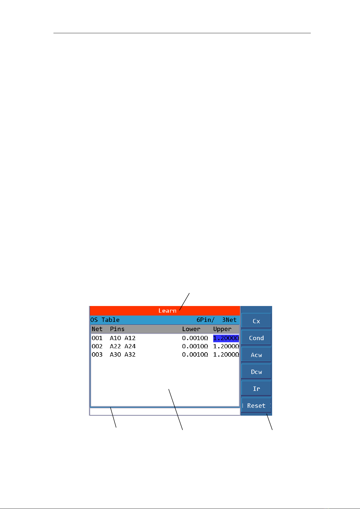
3.4 Learn Interface...........................................................................................................20
3.4.1 Learn ..........................................................................................................20
3.4.2 OSC Network Table...................................................................................21
3.4.3 Offset..........................................................................................................21
3.4.4 HV Net.......................................................................................................23
3.4.5 Conductance Network Editing ...................................................................24
3.5 <MEAS > Interface....................................................................................................24
3.5.1 Title............................................................................................................24
3.5.2 File .............................................................................................................25
3.5.3 Sum ............................................................................................................25
3.5.4 Measurement Result...................................................................................25
3.5.5 Menu ..........................................................................................................25
3.6 <STAT> Interface......................................................................................................26
3.6.1 Overall Statistics ........................................................................................26
3.6.2 Statistics by Items ......................................................................................26
3.6.3 Menu Function...........................................................................................26
3.7 <FILE> Interface........................................................................................................26
3.7.1 Current File: UNNAME (normal)..............................................................27
3.7.2 Internal .......................................................................................................27

TH8601 Operation Manual Contents
III
3.7.3 External......................................................................................................28
3.7.4 Sequential...................................................................................................29
3.8 <SYS> Interface.........................................................................................................30
3.8.1 Measurement..............................................................................................30
3.8.2 Environment...............................................................................................32
3.8.3 Inter telecommunication.............................................................................34
3.9 <UTILI> Interface......................................................................................................37
3.9.1 Pin Search...................................................................................................37
3.9.2 Self Check..................................................................................................38
3.9.3 HV Module.................................................................................................38
3.9.4 I/O Edit.......................................................................................................39
3.9.5 Memory Initialization.................................................................................39
3.9.6 Program Update .........................................................................................40
3.9.7 Pass Word...................................................................................................40
3.9.8 LCR Module...............................................................................................41
Chapter 4 Communication Interface...........................................................................................43
4.1 Handler.......................................................................................................................43
4.1.1 Handler Interface Circuit Diagram.............................................................43
4.1.2 Interface Description..................................................................................43
4.2 RS232 Interface..........................................................................................................44
4.2.1 RS232 Standards........................................................................................44
4.2.2 RS232 Connection .....................................................................................44
4.3 SCPI Commands Reference.......................................................................................45
4.3.1 Setup Command.........................................................................................45
4.3.2 MEASUREMENT COMMAND ...............................................................79
4.3.3 :FETCH Command ....................................................................................82
4.3.4 SYSTEM COMMAND..............................................................................97
4.3.5 File Command..........................................................................................109
4.3.6 DISP COMMAND...................................................................................111
4.3.7 Other Commands .....................................................................................112
4.3.8 Public Command......................................................................................112
Chapter 5 Technical Specifications...........................................................................................113
Chapter 6 Warranty...................................................................................................................114
Chapter 7 Appendix..................................................................................................................115

TH8601 Operation Manual Contents
IV
Announcement
The description of the manual may not cover all contents of the instrument, and our company is
subject to change and to improve the performance, function, inner structure, appearance, accessory
and package of the instrument without notice. If there is puzzle caused by inconsistency of manual
and instrument, then you can contact with our company by the address on the cover.

TH8601 Operation Manual
1
Chapter 1 Unpacking and Installation
This chapter describes some inspections that must be performed after you receive the instrument,
and the conditions that you must understand and have before installing and using the instrument.
1.1 To Inspect the package
After unpacking, you should first check whether the instrument is damaged due to transportation.
We do not recommend that you power on the instrument when the exterior is damaged. Then
confirm according to the following packing list.
TH8601 Cable/Harness Tester ×1
Power cord ×1
Instruction Manual ×1
Automatically find point probe ×1
Adapter Fixture 64 channels with 2 and 128 channels with 4
If there is any discrepancy, please contact our company or the dealer as soon as possible.
1.2 Power connection
Power supply voltage range: 100~242 Vac.
Power supply frequency range: 47 ~ 63 Hz.
Power supply range: not less than 100 VA.
The power input phase cable L, neutral cable N, and ground cable E should be the same as the
power plug of the instrument.
This instrument has been carefully designed to reduce the noise interference caused by the AC
power input, but it should still be used in a low-noise environment. If it is unavoidable, please install
a power filter.
Warning: In order to prevent leakage of electricity from causing damage to the instrument or people,
the user must ensure that the ground cable of the power supply is reliably connected to the ground.
1.3 Fuse
The instrument has been equipped with a fuse when leaving the factory, and the user should use the
fuse provided by our company.
Warning: Before powering on, pay attention to whether your fuse position is consistent with the
supply voltage range

TH8601 Operation Manual
2
1.4 Environment
1) Please do not operate the instrument in the place that is vibrative, dusty, under direct sunlight
or where there is corrosive air.
2) The normal working temperature is 0℃~40℃, relative humidity ≤75%, so the instrument
should be used under above condition to guarantee the accuracy.
3) There is heat abstractor on the rear panel to avoid the inner temperature rising. In order to keep
good airiness, please don’t obstruct the left and right airiness holes to make the instrument
maintain the accuracy.
4) Although the instrument has been specially designed for reducing the noise caused by ac power,
a place with low noise is still recommended. If this cannot be arranged, please make sure to use
power filter for the instrument.
5) Please store the instrument in the place where temperature is between 5℃and 40℃, humidity
is less than 85%RH. If the instrument will not be put in use for a time, please have it properly
packed with its original box or a similar box for storing.
6) The instrument, especially the test cable should be far from strong electro-magnetic field, to
avoid the jamming on measurement.
1.5 Use of Test Fixture
Please use the test fixture or test cable provided by our company. The test fixture or test cable made
by the user or other companies may cause incorrect measurement results.
Precautions:
The shorter the patch cord, the better
Too long external wiring burdens additional flux, which can easily cause false detections for
on-resistance specification testing or short-circuit terminal judgment.
Change the adapter frequently
After the adapter has been used for a long time, the conduction will be unstable when in contact, and
it will cause a false test when testing the low conduction impedance specification; therefore, when
the same good cable is tested multiple times, the poor conduction impedance or intermittence open
-circuit will occure , the adapter needs to be replaced.
Keep jigs and adapters clean
After the machine has been used for a long time, there will be some dust in the fixture. When it is
rainy or the air humidity is high, it will produce poor insulation , which will result in misjudgment
of the insulation resistance specification test.
1.6 Warm-up
1) To guarantee the accurate measurement, the warm-up time is no less than 15min.
2) Please not turn on or off instrument frequently, in order to avoid the inner data fluster.

TH8601 Operation Manual
3
1.7 Other features
1) Power: consumption power≤100VA.
2) Dimension (W*H*D): 425mm*189mm*357mm
3) Weight: About 13kg.

TH8601 Operation Manual
2
Chapter 2 Introduction
This chapter describes the basic operating features of TH8601 series instruments. Before using the
TH8601 series instrument, please read this chapter carefully so that you can quickly learn the
operation of TH8601.
2.1 Introduction to front panel
Figure 2-1 shows the front panel of TH8601.
POWER
PrtScn
高压
合格
不良 停止
启动
确定
保存
测试 设置 学习 统计 文件 系统 辅助
A B
C D
E F
G H
Return
取消
Pin Search
Hipot
Calibration
(-)(+)
4-WIRE UNIVERSAL CABLE/HARNESS TESTER
29 28 27
21 3 4 5 6 9
21 20 19
10
87 11 12 13 14 15 16 17 18
2223242526
SAVE
ENTER
ESC
MEAS SETUP LEARN STAT UTILI
SYS
FILE
PASS
FAIL
HV 7PQRS
+/-
TEST
EXIT
8 9
TUV WXYZ
4GHI 56
JKL MNO
1 2 3
ABC DEF
0
Figure 2-1 Front panel
1) Brand and model
Model
Chanel
TH8601A
64
TH8601
128
2) LCD liquid crystal display
800x480 color TFT LCD display, display measurement results, measurement conditions, etc.
3) [PrtScn] key
Screen copy button, intercept the entire LCD screen and save it to the U disk in the format of a
picture.
4) Menu key
Six menu keys can be used for menu control, and each menu key has a corresponding menu
function on the left. The definition of the menu key changes with the display page and cursor
position.
5) HV indicator
Indicates that a high-voltage test is in progress and warns of high-voltage danger.

TH8601 Operation Manual
3
6) PASS indicator
Test qualified LED indicator.
7) [MEAS] page buttons
Press the [MEAS] key to enter the page that displays the measurement steps and measurement
results of the current file.
8) [SETUP] page buttons
Press the [SETUP] key to enter the current measurement parameter setting page.
9) [ ] key
This key is used to quickly turn pages for easy viewing of measurement results.
It can also be used to set parameter items, for example:
If you want to set the edge judgment function on or off, when you press this button, the edge
judgment is set to ON;
When it is pressed again, it is turned off when setting; when it is pressed again, it is set to on; in
this way, every time it is pressed,
Each time you press, the set value will change once, until the set value you need appears, the
setting is complete.
10) [LEARN] page buttons
Press the [LEARN] key, the instrument will perform the learning test, and enter the learning
page after completion, and display the learning results.
11) [STAT] page button
Press the [STAT] key to enter the statistical measurement result page.
12) [FILE] page button
Press the [FILE] key to enter the file management setting page.
13) [SYS] page button
Press the [SYS] key to enter the system setting page.
14) [UTILI] page buttons
Press the [UTILI] key to enter the auxiliary function setting or measurement page.
15) [←] key
BACKSPACE key. Press this key to delete the last number or letter of the entered value.
16) USB HOST interface
It is used to connect the U disk storage to save and recall files.
It is also used for program upgrades.
17) [TEST] key
Press the [TEST] key to start the test.
18) [EXIT] key
Press the [EXIT] key to stop the test.
19) [ENTER] key
[ENTER] key is used to confirm data input.
20) [SAVE] key
[SAVE] key, save key. Used to save files.
21) [ESC] key
[ESC] key is used to cancel data input.
22) Numerical keys
The numeric keys are used to input data. The numeric keys are composed of number keys [0]

TH8601 Operation Manual
4
to [9], decimal point [.] and [+/-] keys.
Also used for text input. In addition to 0-9, you can also enter 26 letters fromA to Z.
23) Cursor keys (CURSOR)
The cursor keys are used to move the cursor between the fields on the LCD display page.
When the cursor moves to a certain field, the field will be highlighted on the LCD screen.
24) Test terminal [UNKNOWN]
32PIN fixture connector, 128Pin in the picture, a total of 4 slot connectors.
25) FAIL indicator
Bad test LED indicator.
26) [RETURN] key
The return key is used to return the cursor on the current interface to the starting position.
It is also used to return to the local area during remote communication.
27) [Pin Search] interface
This interface is connected to the meter pen, used for point search and point test.
28) [Hipot Callbration] interface
This interface is a pair of high-voltage output terminals, red for high end and black for low end.
Used for voltage output during high voltage calibration
29) Power switch (POWER)
Switch.
2.2 Introduction to rear panel
Figure 2-2 shows the rear panel of TH8601.
RATING FUSE
T2AL 250V
~
~
T4AL 250V
!
TO AVOID ELECTRIC SHOCK,
THE POWER CORD PROTECTIVE GROUNDING CONDUCTOR
MUST BE CONNECTED TO GROUND.
DISCONNECT POWER SUPPLY BEFORE REPLACING FUSE.
WARNING
110V/60Hz 100VA
220V/50Hz 100VA
RS-232C LAN GPIB USB HANDLER
1 2 3 4 5
8 7 6
Figure 2-2 Rear panel
1) RS232C serial interface
The serial communication interface realizes online communication with the computer through
instructions.
2) LAN interface
The network interface realizes online communication with the computer through instructions.
TH8601 Operation Manual
5
3) IEEE-488 interface
The GPIB interface realizes online communication with the computer through instructions.
4) USB DEVICE interface
The USB communication interface realizes online communication with the computer through
instructions.
5) HANDLER interface
HANDLER interface, realize control and communication with computer through level signal.
6) Nameplate
Indicate production date, instrument number, manufacturer and other information.
7) Chassis ground terminal
This terminal is connected to the instrument chassis. Can be used to protect or shield ground
connections.
8) Power socket
Used to input AC power.
2.3 Introduction to display zone
TH8601 uses a 7-inch widescreen TFT display with 65k colors, and the content displayed on the
display is divided into the following display areas, as shown in the figure:
1
4 2 3
Figure 2-3 display zones

TH8601 Operation Manual
6
1. Title area
Used to display the name of the current page.
2. Main display area
Used to display the main content of each interface
3. Menu area
Used to display menu items, a total of 6
4. Information area
Used to display prompt information, inquiry information, error information, etc.
Main menu buttons and corresponding displayed pages.
2.4 Basic Operation
The basic operation of TH8601 is as follows:
Use the menu buttons ([MAES], [SETUP], [LEARN], [STAT], [FILE], [SYS], [UTILI]) and soft
keys to select the page you want to display.
Use the cursor keys ([↑] [↓] [←][→]) to move the cursor to the field you want to set. When the
cursor moves to a certain field, the field will be highlighted. The so-called domain is the area where
the cursor can be set.
The corresponding menu function of the current cursor area will be displayed in the "menu area".
Select and press the desired soft key. The number keys, [←] key and [ENTER] key are used for data
input.
When a number key is pressed, the corresponding English letters and numbers will be displayed in
the soft key area. Select and press the required software. When the [ENTER] key is used to end the
data input, the data unit is the default unit of the corresponding domain parameter: Hz, V or Ω. For
example, the default unit of test frequency is Hz.

TH8601 Operation Manual
7
Chapter 3 Detailed Operation
3.1 Booting
Plug in the three-cable power plug. Note: Keep the power supply voltage and frequency in
compliance with the above regulations. The power input phase line L, neutral line N, and ground
line E should be the same as the phase line and neutral line on the power plug of the instrument.
Turn on the power and press the power switch at the lower left corner of the front panel to turn on
the instrument and display the startup screen.
The figure below shows the startup screen of TH8601. It also shows the company LOGO,
instrument model (TH8601), and software version number (Ver 1.00).
After the system is loaded, it will eventually stop at the page shown in the figure below: This page is
called the main interface.
3.2 Main Interface
After booting, the page entered is the main page.
The main page mainly displays software related information and company contact information. As
shown below:

TH8601 Operation Manual
8
The menu function has the following 3 items:
2.1 Brightness + in the figure is to increase the brightness of the display.
2.2 Brightness -in the figure is to reduce the brightness of the display.
2.3 View network is the network table used to view the current test file.
2.4 Lock is used for key lock.
3.3 SETUP Interface
Press the module button [SETUP] to enter the <Setup> page .As shown:
Figure 3.3-1 Setup Page
The <Settings> page includes 6 sub pages including Mode, OS, Cond, LCR, HV and Item. The
following paragraphs explain each setting page in details.
Press the number 1~6 in the numeric keyboard to quickly enter the corresponding setting page.

TH8601 Operation Manual
9
3.3.1 <Mode>
The information page mainly sets some features about the cable, including the following:
Product Name (Name)
The name consists of letters, numbers, and a dash (-), with a maximum of 8 characters.
Cable Type (Cbl Type)
Move the cursor to the Cable Type field. The following options are displayed in the menu area.
Double: Both ends of the cable are plugged into the instrument for testing, also called double-sided
cable.
Single: one end of the cable is plugged into the tester for testing, also called unilateral cable
Probe: refers to using test probe to test.
Learn: You can learn the sample under test through Learn in the menu function, and you can
automatically obtain the type of tested product.
Probe Tip Type (Prt. Type)
Standard: Both terminals of the cable are single-ended.
One AB: One end of the cable has two sidesAB.
Two AB: The two ends of the cable have two sides AB.
Chip Type(I2C Mode)
Move the cursor to the I2C Mode field. The following options are displayed in the menu area.
No chip: refers to the cable without a chip.
Light: Refers to the cable with Lightning chip.
OPPO: Refers to the cable with OPPO chip.
VIVO: Refers to the cable with VIVO chip.
TypeC: Refers to the cable with TypeC chip.
Terminal A Start Point
Please use the number keys to input as needed, the range is A1~A64; if this terminal is not
used, it can also be turned off.
Terminal A End Point
Please use the number keys to input as needed, the range is A1~A64; if this terminal is not
used, it can also be turned off.
Terminal B Start Point
Please use the number keys to input as needed, the range is B1~B64; if this terminal is not
used, it can also be turned off.
Terminal B End Point
Please use the number keys to input as needed, the range isB1~B64; if this terminal is not
used, it can also be turned off.
Terminal C Start Point
Please use the number keys to input as needed, the range is C1~C32; if this terminal is not
used, it can also be turned off.
Terminal C End Point
Please use the number keys to input as needed, the range is C1~C32; if this terminal is not
used, it can also be turned off.
Terminal D Start Point
Please use the number keys to input as needed, the range is D1~D32; if this terminal is not

TH8601 Operation Manual
10
used, it can also be turned off.
Terminal D End Point
Please use the number keys to input as needed, the range is D1~D32; if this terminal is not
used, it can also be turned off.
3.3.2 < OS>
Used to set OS related test conditions, as shown in the figure below: OS Setup page.
Figure 3.3-2
OS Standard (Os Std.)
Set the threshold for judging OS; the threshold range is 1kΩ~50kΩ.
It is used to judge whether the double-sided cable is a path or an open-circuit.
For example, OS standard: set to 2k
If the resistance between the two ends of the cable is greater than 2k, then it means an open circuit
If the resistance between the two ends of the cable is less than 2k, it means a path or a short circuit.
Distributed Capacitance Sensitivity (Cx Std.)
Set the single-side capacitance value; either manually input or obtain the capacitance value by
learning standard parts, the setting range is 0.1pF~9.9999nF.
Whether the single-side cable is open or not is judged by measuring the size of its distributed
capacitance. The distributed capacitance of the single-side cable is the unilateral sensitivity.
For example, unilateral sensitivity: set to 100pF
If the unilateral sensitivity of the cable is greater than 100pF, it means that there is no open circuit in
the cable.
If the unilateral sensitivity of the cable is less than 100pF, it means that the cable has an open circuit.
Side Judgment (Side jdg.)
OFF: Turn off the side judgment function.
ON: Turn on the side judgment function.
Side: enable the side judgment function, and short-circuit the slot judgment.
What is judgment by slot division, let's illustrate with examples:
Assuming a short circuit, there are 4 possibilities, namely:
A1-A2, A1-B2, A2-B1, B1-B2
Since a short circuit cannot occur between A slot and B slot, we reduce the short circuit point to the

TH8601 Operation Manual
11
inside ofA slot and B slot. So 4 possibilities have become 2 possibilities, namely: A1-A2, B1-B2
Then test the conductance of A1-A2 and B1-B2 respectively, and the smaller one is the short-circuit
point.
ExcludingA1-B2, the screening behavior ofA2-B1 is the edge separation function.
%: Turn on the side judgment function and judge the position of the break point, expressed in %.
For example:
The result of the test is 50%, which means that the break point is in the middle of the cable.
Capacitance Speed (C.T.Spd)
Slow
Med
Fast
Set the sweeping test speed of unilateral sensitivity. The slower the speed, the higher the test
accuracy.
For example:
The length of a cable under test is only 5cm, and its unilateral sensitivity is very small, only about
5pF. In order to ensure the accuracy of the test, the test speed is set to slow, and the test stability
reaches 1pF, which meets the test requirements.
Interval OS Time (IOS Time)
Set the interval open and short circuit test time, the setting range is 0~999.9S.
If it is 0 seconds, it means unlimited time, and the test will not be terminated until the tested product
is removed or the STOP button is pressed.
Interval Short Time (IOP Time)
Set the interval short -circuit test time, the setting range is 0~999.9S.
If it is 0 seconds, it means unlimited time, and the test will not be terminated until the tested product
is removed or the STOP button is pressed.
Hull Pin (Hull Pin)
The pins connected to the hull, can be manually inputted or the points can be found through the test
leads.
In addition, the hull pin is used for trigger testing.
For some DUTs of connector type, if you want to automatically trigger the test, it is not feasible to
rely on the traditional unilateral sensitivity to judge, because the unilateral sensitivity of the DUT is
often less than 1pF and cannot be accurately measured.
Therefore, connect its hull to the test port, when the operator takes the tested part and inserts it into
the jig for testing, the instrument will scan a distributed capacitance brought by the human body, this
capacitance can be accurately measured, so as to achieve the purpose of automatically triggering the
test.
C Exist (C Exist)
None
Exist
Whether there is a large capacitance between the lines, and use the large capacitance as the dividing
point to divide the network table.
OS Speed (OS Speed)
When sweeping the cable loop, how much to delay, then read back the level. The size of this
parameter depends on the size of the capacitance between the lines, the larger the capacitance, the

TH8601 Operation Manual
12
longer the delay. The default is 0us.
Sweeping Method (OS Meth)
Dich.
One
Dichotomy, fewer scans, high speed, its number of times is log2(N), where N is the total number of
pins, for example, a 64Pin cable requires 6 times.This method is suitable for pure thread products
One corresponds to the other
Sweep each pin one by one, its number of times is N, in other words, N pins need to sweep N times.
Although this method is much slower than the dichotomy, it is suitable for products with passive
components.
Fast Interval Open-Circuit (IO Speed)
The fast mode of interval open-circuit, normal interval open-circuit can only detect 4ms width
interval open-circuit.
But when the fast interval open-circuit is turned on, the interval open-circuit with a width of 5us can
be detected.
Note: fast interval open-circuit also requires special tooling to match it before it can be used.
After Fail (Aft Fail)
Empty
Short
Open
Repeat
When the trigger mode is automatic, when a OS circuit is tested, if a fault occurs, under what
conditions need to end the test and report the OS circuit failure.
Empty spot stop: When the test piece is removed, that is, the sweeping end shows an empty network
state, and the instrument ends the test.
Short-circuit stop: When a short-circuit failure occurs, the instrument ends the test.
Open circuit stop: When a open-circuit failure occurs, the instrument ends the test.
Repeat stop: When the same bad condition occurs N times (N can be set), the instrument ends the
test.
Negative Timer (NG Timer)
As mentioned above, negative repeated N times, the instrument ends the test, this N times is to set
here.
Rigid OS
In traditional OS circuit, a resistance of Nk (the value range of N is 1~50) is used as the dividing
line, <Nk is short-circuit, and >Nk is open-circuit.
This kind of rough division method has poor accuracy and often cannot describe the accurate
network structure of the DUT.
Therefore, after the traditional OS circuit sweeping, the conductance sweeping is added to further
analyze the network structure.
If it is set to 10 ohms here, then it will be considered as a short circuit based on the sweeping
resistance value <10, and >10 judged as open circuit.
TH8601 Operation Manual
13
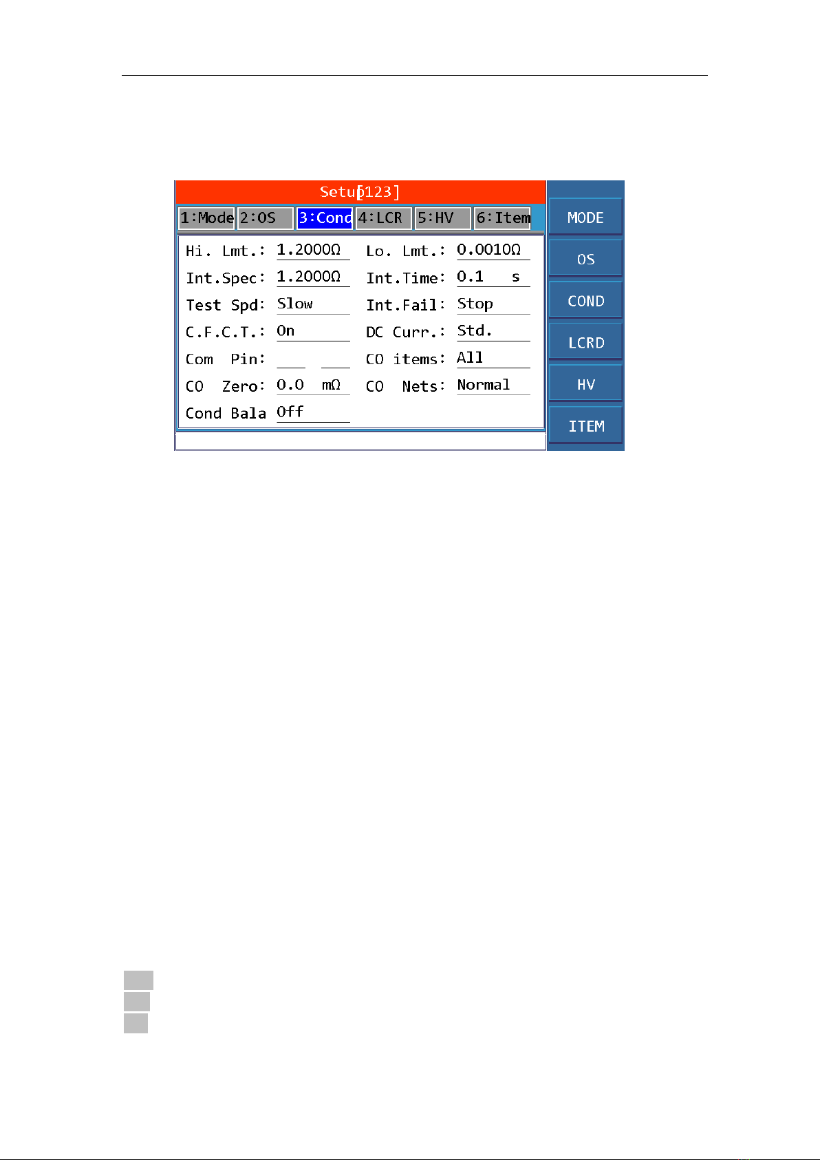
3.3.3 Conduction
Used to set the relevant test conditions for conduction, as shown in the figure:
Figure 3.3-3 Conduction Page
High Limit (Hi. Lmt.)
Set the high limit of the conductance value, the setting range is 0 Ω ~ 2000 Ω.
The high limit of the specification used to judge whether the conductance is qualified.
You can directly input or connect to the tested sample through the numeric keyboard to learn and
obtain a measured value as a reference value.
Low Limit (Lo.Lmt.)
Set the low limit of the conductance value, the setting range is 0Ω ~ 2000Ω.
The low limit of the specification used to judge whether the conductance is qualified.
You can directly input or connect to the tested sample through the numeric keyboard to learn and
obtain a measured value as a reference value.
Interval Specifications (Int. Spec)
Set the high limit of the change value of the interval conductance test.
The high specification limit used to judge whether the interval conductance resistance is qualified.
You can directly input through the numeric keyboard or directly copy the high conductance limit
above.
For example, the conductance resistance value of A1-B1 is 0.985 ohms
Then in the interval conductance test, A1-B1 was tested N times, N conductance values are
generated, then change value = maximum value-minimum value, If the change value> this interval
specification value, then judged as negative.
Interval Time (Int. Time)
Set the time to measure the interval conductance resistance, the setting range is from 0.1s to 999.9s.
It cannot be set to 0s, and unlimited time testing is not supported.
Test Speed (Test Spd)
Slow
Med
Fast
Set the sweeping test speed of the conductance resistance, the slower the speed, the higher the test

TH8601 Operation Manual
14
accuracy.
For example:
A certain cable under test, the cable length is only 5cm, its conductance resistance is very small,
only about 5mΩ.To ensure the accuracy of the test, the test speed is set to slow, and the test stability
is up to 1mΩ, which meets the test requirements.
Interval Fail (Int. Fail)
Stop
Cont.
What to do when the interval conductance test is negative: whether to stop the test and report FAIL
immediately or complete the test and report FAIL later.
Error Loop (C.F.C.T.)
OFF
ON
When error loop is turned on, when the conductance test is failed, the instrument will cyclically test
the conductance resistance value of this pin, and displayed on the test page, the test can be
continued until the test passes. You can also press the STOP button to stop the test, and the
instrument will directly report the FAIL result.
Test Current (DC Curr.)
Standard
The test current of the conductance resistance can be set from 1mA to 20mA, if the standard is
selected, it is 20mA.
Conductance Network (Co Nets)
Normal
Stars
A - B
Mix
The pin combination mode of conductance resistance:
Normal: Conduct the conductance test on two adjacent short-circuit pins, for example: a certain
network is: A1-A2-A3-B1, then you need to test 3 groups of conductance resistance, which are:
A1-A2
A2-A3
A3-B1
Stars: First, we must set a common pin, then combine with other pins to form test pins.
For example, setA1 as a common pin, then the conductance resistance test pin combinations are:
A1-A2
A1-A3
A1-B1
A - B: The pins of different sockets match each other, and then the conductance pin will become:
A1-B1
A2-B1
Table of contents
Popular Test Equipment manuals by other brands


Redtech
Redtech TRAILERteck T05 user manual

Venmar
Venmar AVS Constructo 1.0 HRV user guide

Test Instrument Solutions
Test Instrument Solutions SafetyPAT operating manual

Hanna Instruments
Hanna Instruments HI 38078 instruction manual

Kistler
Kistler 5495C Series instruction manual

Waygate Technologies
Waygate Technologies DM5E Basic quick start guide

StoneL
StoneL DeviceNet CK464002A manual

Seica
Seica RAPID 220 Site preparation guide

Kingfisher
Kingfisher KI7400 Series Training manual

Kurth Electronic
Kurth Electronic CCTS-03 operating manual

SMART
SMART KANAAD SBT XTREME 3G Series user manual

Agilent Technologies
Agilent Technologies BERT Serial Getting started