Channel MCT User manual

CHANNEL SAFETY SYSTEMS t: 0845 884 7000 | w: www.channelsafety.co.uk
INSTRUCTION MANUAL - Issue 1 - 02/2014 | 1
INSTRUCTION MANUAL
CHANNEL SAFETY SYSTEMS t: 0845 884 7000
Peterseld Business Park f: 0845 884 6000
Bedford Road
Peterseld
Hampshire e: sales@channelsafety.co.uk
GU32 3QA w: www.channelsafety.co.uk
Emergency lighting conversion kits
from Channel Safety Systems
MCT
E
m
e
r
g
e
n
c
y
li
g
h
t
i
n
g
c
o
n
v
e
r
s
i
o
n
ki
t
s

CHANNEL SAFETY SYSTEMS t: 0845 884 7000 | w: www.channelsafety.co.uk
INSTRUCTION MANUAL - Issue 1 - 02/2014 | 2
INTRODUCTION
Thank you for choosing this conversion kit, this leaet will enable you to get the best from it and ensure that installation and operation will be straightforward
and reliable. The unit has been designed to provide exibility in xing and ease of wiring to give trouble free operation
DESCRIPTION
The conversion kit comprises of a charger/inverter unit and battery pack. The unit houses a constant current battery charger, with charge indicator and solid
state inverter circuitry, controlled by a safety cut-out disconnect circuit which prevents deep discharge of the battery pack. Changeover is achieved by a
voltage sensitive internal relay controlled by the permanent mains supply. This ensures prompt adoption of the emergency supply to the lamp during partial
and momentary failure of the general lighting supply. The battery pack consists of nickel cadmium cells suitable for high temperature use. These are charged
continuously by the conversion unit and are therefore kept at full charge in readiness for an emergency situation. Healthy charging is
shown by a green LED indicator.
COMMISSIONING
After installation follow the check list below to ensure that the conversion unit is operating as intended.
1. Connect the batteries to the module. For safety reasons terminate all battery leads to module before connecting push-on terminals to battery.
2. Energise the permanent mains supply (live charger), a click should be heard as the internal relay operates.
3. Check thc green charge LED indicator is lit, this shows that the battery is charging healthily.
4. De-energise the permanent mains supply (live charger). check the lamp lights, it may be weak or go out after a few seconds, this simply indicates the
batteries are in the discharged state. (The batteries are supplied discharged for safety reasons.)
5. Restore the permanent mains supply.
6. Energise the switched mains supply (live switched), check the lamp lights from the mains, it will be much brighter than when tested at (4) and the starter
switch where used will glow and click until the lamp strikes.
7. Leave the unit in this state for about I hour, then repeat test (4), whereupon the lamp should operate at reduced emergency output for about ve
minutes.
Obviously any practical layout will not fully satisfy all of these requirements and therefore a compromise will have to be made bearing in mind that excessive
battery temperatures will shorten its life considerably. Ultimately remote housing‘or the battery pack and possibly the conversion unit as well, will have to be
considered, however cable lengths should be kept to a minimum. THE UNIT IS NOT GENERALLY SUITABLE FOR REMOTE MOUNTING MORE THAN 0.5m
FROM THE LUMINAIRE.
For safety reasons the conversion module should always be mounted either within the luminaire itself or a suitable remote housing
E. M. C. INSTALLATION GUIDE (Electromagnetic Compatibility)
This conversion module is carefully designed to minimise E. M. C. and to enable the unit to be CE marked. Great care must be taken in wiring thc conversion
module to ensure that the E.M. compatibility is preserved to allow the complete converted luminaire to be CE marked. The rules below should be followed
as a guide to obtaining the best performance. Failure to observe these rules or failure to have the completed luminaire tested may contravene the E. M. C.
regulation. If however you arc in any doubt about CE marking the converted luminaire, then it should be sent for a factory conversion.
E. M. C. RULE 1
The incoming mains wires should be kept as short as possible within the luminaire and the conversion module shouLd be positioned accordingly.
E. M. C. RULE 2
The incoming mains and the lamp output wiring should be kept as far apart as possible.
E. M. C. RULE 3
Consult the mains control gear data for guidance regarding selection of the emergency lamp and installation wiring.
CHANNEL SAFETY SYSTEMS t: 0845 884 7000 | w: www.channelsafety.co.uk
INSTRUCTION MANUAL - Issue 1 - 02/2014 | 3
INSTRUCTIONS
Careful preparation will ensure a quick and ecient conversion. Study the internal arrangement of the luminaire, the objectives in order of priority are:
1. To keep the battery pack as far away as possible from any sources of heat, ie. the mains chokes, etc.
2. To keep the conversion unit away from any sources of heat.
3. To minimise changes in wiring, and the internal layout of the existing mains circuitry components.
Ratings Section
See conversion module battery for ratings
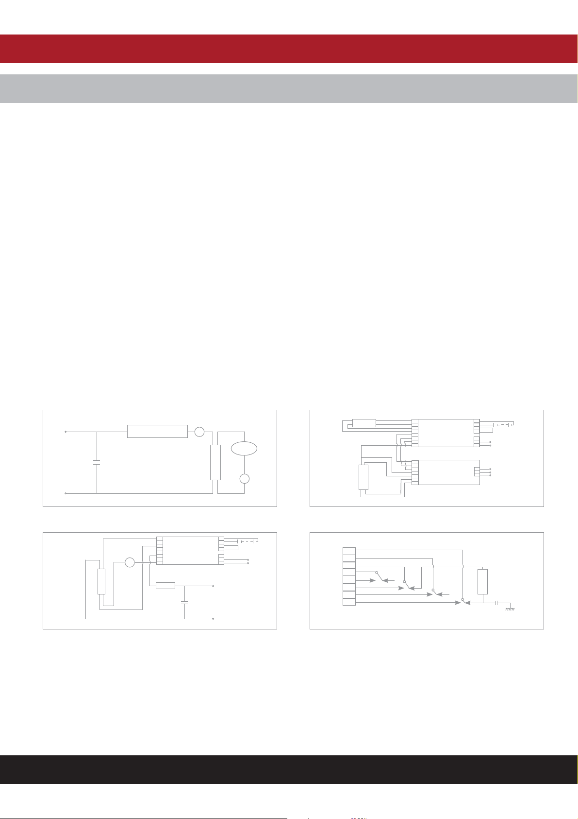
Conversion Of Single Lamp Switch Circuits
Circuit before modication comprising: Single mains input (Live, Neutral, Earth). Single iron cored mains choke, single lamp, glow type or electronic starter
switch with two terminals and power factor correction capacitor (PFC) if tted.
Conversion Procedure
Extend or shorten conductors as necessary, using only single conductor 90C heat resistant wire. (Use only ONE wire in each terminal.) Refer to diagrams
1 and 2.
1. Ensure all power is OFF and batteries are disconnected
2. Cut conductor (A) from choke to lamp. - Put choke end into terminal 6 - Put lamp end into terminal 3
3. Cut conductor (B) from lamp to starter. - Put starter end into terminal 8 - Put lamp end into terminal 1
4. Connect neutral supply to terminal 'N'
5. Connect the Permanent Live to terminal Ph
6. IMPORTANT MCT CASE MUST BE EARTHED. Secure the Flange of the MCT case to Earthed metalwork using the screws and Nuts provided.
General Conversion Notes
Before conversions start, a trial run on the bench often helps not only to become familiar with the conversion procedure, but also to verify that the
luminaire close in fact work property before any changes are made.
Emergency Module
Emergency Module
N
N
N
E
Typical Twin Lamp
HF Control Gear
N
S
T
1
1
2
2
3
3
4
4
5
5
6
6
7
7
8
2
1
Emergency
Inverter
2
3
4
5
6
7
8
3
4
5
6
7
8Lch
Lch
Lsw
Lsw
PFC
L
A
M
P
LAMP
L
A
M
P
Conversion of Twin Lamp H.F. Ballast
Internal Relay Conguration shown in emergency conditionsLamp Wiring After Conversion
Choke
Starter
L
N
PFC
A
B
L
A
M
P
Lamp Wiring Before Conversion
Choke

CHANNEL SAFETY SYSTEMS t: 0845 884 7000 | w: www.channelsafety.co.uk
INSTRUCTION MANUAL - Issue 1 - 02/2014 | 4
BALLAST LUMEN FACTOR (%)
LAMP WATT LAMP TYPE MCT/M3/70 MCT/M3/58 MCT/M3/36
70 T8 9 - -
65 T12 9 - -
58 T8 9 7 -
55 PL-L - - -
40 PL-L - - -
40 CIRC 10 8 -
40 T12 10 7 -
38 2D 10 8 -
36 T8 12 8 8
36 PL-L 10 9 8
32 CIRC 12 10 8
30 T8 14 11 9
28 2D 13 11 10
26 PL-D 14 12 10
24 PL-L 15 11 11
22 CIRC 17 13 11
21 2D 16 14 13
20 T12 17 14 12
18 T8 17 14 11
18 PL-D 17 14 12
18 PL-L 16 15 12
16 2D 18 15 13
13 PL-D 22 17 16
13 T5 22 18 16
11 PL-S 25 22 19
8 T5252118
7PL-S282420
6 T5302522
5PL-S352824
4 T5393328
BLF Measurements for MeT Conversion Modules

CHANNEL SAFETY SYSTEMS t: 0845 884 7000 | w: www.channelsafety.co.uk
INSTRUCTION MANUAL - Issue 1 - 02/2014 | 5
Luminaire Location: .....................................................................................................................................................................
In Case of Fault Contact: ..............................................................................................................................................................
Duration 3 Hours Tube Type: 8 Watts ..........................................................................................................................................
FIRST YEAR SECOND YEAR THIRD YEAR FOURTH YEAR FIFTH YEAR
MONTH TEST SIGN DATE SIGN DATE SIGN DATE SIGN DATE SIGN DATE
1 Functional
2 Functional
3 Functional
4 Functional
5 Functional
6 Functional
7 Functional
8 Functional
9 Functional
10 Functional
11 Functional
12 3 hour
TESTING
The luminaire must be checked periodically for correct operation, and to evaluate the remaining capacity in the battery at regular intervals during its life. The
unswitched supply should be failed which will cause the luminaire to operate in the emergency mode.
• The LED charge indicator should be checked on a daily basis.
• Every month the luminaire should be tested in the emergency mode to ensure the lamp is illuminated.
• Annually the luminaire should be tested to ensure it achieves its entire rated duration of emergency operation.
• Record the periodic testing of individual luminaire in the table below, and keep all records in a safe place.
IF THE LUMINAIRE FAILS TO ACHIEVE ITS RATED DURATION, THE BATTERIES MUST BE REPLACED, OF AN IDENTICAL
TYPE, SEE THE LABEL ON THE BATTERY FOR THE ORDER REFERENCE.
FLUORESCENT TUBES MUST BE CHANGED AT THE FIRST SIGNS OF BLACKENING.

INSTRUCTION MANUAL
CHANNEL SAFETY SYSTEMS t: 0845 884 7000
Peterseld Business Park f: 0845 884 6000
Bedford Road
Peterseld
Hampshire e: sales@channelsafety.co.uk
GU32 3QA w: www.channelsafety.co.uk
Table of contents
Other Channel Lighting Equipment manuals

Popular Lighting Equipment manuals by other brands


Saxby Lighting
Saxby Lighting HeroPro CCT Microwave Emergency instruction manual

Chauvet
Chauvet SlimPAR Tri IRC 7 IRC user manual

Velleman
Velleman HQ POWER VDL6PDB user manual

Laserworld
Laserworld GREEN-12000 user manual

BION TECHNOLOGIES
BION TECHNOLOGIES PS | tellus po rd xs user manual

Ryger
Ryger Defender DMX Range instruction manual