FLUVO schmalenberger NTG700 rondo User manual
GB
27213 - E.1
NTG700 rondo


CONTENTS
3
NTG700 rondo
Version: 27213 - E Schmalenberger GmbH + Co. KG
D-72072 Tübingen / Germany
Contents
1 General..................................................................................................4
2 Safety Instructions............................................................................... 4
3 Unit Description / General Technical Data.........................................6
4 Installation Site Specifications and Installation................................ 9
4.1 Base frames for the installation ...........................................................................................9
4.2 Planning the pump pit........................................................................................................10
4.3 Installation Preparations / Concrete pool...........................................................................10
4.4 Installation Preparations / Pre-fabricated pool...................................................................11
4.5 Installation Preparations / Wood-liner pool........................................................................12
4.6 Installation - general ..........................................................................................................12
4.7 Installation kit Installation / Pre-fabricated pool .................................................................13
4.8 Installation kit Installation / Wood-liner pool.......................................................................14
4.9 Pump Kit Installation..........................................................................................................15
4.10 Mounting the face plate assembly.....................................................................................17
5 Electrical Connections....................................................................... 20
5.1 Electrical Connections - general........................................................................................20
5.2 Electrical Connections AC ................................................................................................22
5.3 Electrical Connections three-phase current ......................................................................23
6 Start-up / Operating............................................................................ 24
7 Shutdown / Overwintering................................................................. 26
7.1 Empty the pool...................................................................................................................26
7.2 Face plate assembly overwintering ...................................................................................26
7.3 Emptying the pump............................................................................................................26
8 Maintenance / Repairs........................................................................ 27
8.1 General Instructions...........................................................................................................27
8.2 Maintenance / Service.......................................................................................................27
8.3 Repairs ..............................................................................................................................27
9 Spare parts.......................................................................................... 27
10 Spare Parts List and Drawing........................................................... 28
10.1 Spare Parts List.................................................................................................................28
10.2 Drawing..............................................................................................................................31

OPERATOR‘S MANUAL
4 NTG700 rondo
Version: 27213 - E
Schmalenberger GmbH + Co. KG
D-72072 Tübingen / Germany
1 General
1.1 Guarantee notice
If the instructions contained in this operator’s manual are not observed then any claims un-
der guarantee shall be void.
1.2 General
All parts coming into contact with media are designed for water quality to DIN 19643.
This counter-current swimming system is of state-of-the-art technology.
This manual does not take into account local regulations, the observance of which is the
responsibility of the operator – also on behalf of installation personnel that may be invol-
ved.
The performance label specifies the machine series, the frame size, the most important
operating data and the serial number. Please be sure to quote it in case you require more
information and also when placing subsequent orders or ordering spare parts.
1.3 Usage Instructions
The counter-current system was designed for use in private swimming pools. Consequent-
ly it must not be installed in public swimming pools. Neither the entire unit nor parts thereof
must be used in other systems. You are expressly directed to use it only in accordance with
these instructions.
The counter-current system must not be operated beyond the parameters stated in the
technical data (3.1) . In case of doubt, please contact your customer service or the manu-
facturer.
2 Safety Instructions
2.1 General
• Prior to starting up, make sure that the operators have read and understood the
operator’s manual. Not the operator but the owner is responsible for safety!
• Make sure that the relevant safety regulations and laws are observed in the operating
company and / or country where the counter-current systems are to be used.
• All parts that come into contact with the medium are resistant to an absolute salt con-
tent of up to 0.75% (4,500 mg/l Cl-). If the salt concentrations are greater than this, the
manufacturer must be consulted.
• Use the counter-current system only if it is in perfect technical condition, in accordance
with the regulations, observing safety requirements and danger conditions and strictly
adhering to all the instructions in the operator’s manual!
• Promptly remedy any faults that could influence safety.
For more details of safety instructions please see the operator´s manual
WK (27220).

OPERATOR‘S MANUAL
5
NTG700 rondo
Version:27213 - ESchmalenberger GmbH + Co. KG
D-72072 Tübingen / Germany
2.2 Symbols
In these operating instructions the following symbols are used to draw your special atten-
tion to dangers:
Notices attached directly to the counter-current system , e.g. the arrow indicating the di-
rection of rotation, must always be observed and maintained in a clearly legible condition.
2.3 Safety Instructions for the Operator
1. Electrical equipment must be installed and maintained by qualified electricians. The ap-
propriate local safety requirements and installation regulations must be observed. The
expression “qualified person” is defined in VDE 0105 and IEC 364 There is no informa-
tion contained in this operator’s manual for unqualified persons. It must be pointed out
that EU regulations prohibit the use of unqualified persons on electrical systems.
2. The details on the type plate must correspond to the electrical supply being connected
to.
3. The counter-current system may only be operated using an earth leakage circuit brea-
ker.
4. Under no circumstances must there be any conducting connection between the metal
parts of the motor and the water.
5. If the counter-current system is built into a pump pit then it must be ensured that there
is enough ventilation (for cooling the motor) and enough drainage facility for leaked wa-
ter (at least DN 40).
6. Prior to carrying out repairs to the counter-current system it must be isolated from the
electrical supply and protected from unintentional switching on.
7. Regardless of what nature they may be, repairs must only be carried out by qualified
persons and the counter-current system must be emptied first.
8. The operator must ensure that
- the operator’s manual is always available for users to read,
- instructions in the operator’s manual are being observed,
- the counter-current system is immediately stopped if abnormal electrical voltages,
temperatures, noises, vibrations, leakages or other faults should arise.
Warning! Danger of injury! / Warning! Risk of damage!
This symbol warns you of dangers through mechanical effects and also warns
of handling that could damage the product.
Warning! Mortal danger!
This sign warns you of the danger from electric shocks.
9. Persons who are likely to be endangered by radio waves (e.g. wearers of
heart pace makers) should not linger close to this counter-current swim-
ming system with radio control. In such cases it is recommended to employ
some other form of control (external or pneumatic).

OPERATOR‘S MANUAL
6NTG700 rondo
Version: 27213 - E
Schmalenberger GmbH+ Co. KG
D-72072 Tübingen / Germany
3 Unit Description / General Technical Data
• The counter-current system complies with VDE (Association of German Engineers) re-
gulations.
• The electric motor and the water conducting plastic pump are electrically separated.
• The electric motor complies with protection class IP 55.
• The entire counter-current system complies with protection class I.
The counter-current system is delivered as 3 assemblies:
1. Pump kit 2. Assembly kit 3. Installation kit
3.1 Technical Datan
*AC = Alternating current
3.2 Device Units
System type NTG700rondo
1,5 NTG 700 rondo
1,5 WS* NTG700rondo
1,9 NTG 700 rondo
1,9 WS * NTG700 rondo
3,0
Power 1,5 kW 1,5 kW 1,9 kW 1,9 kW 3,0 kW
Voltage [V] 400 Y / 230 D230 D400 Y / 230 D230 D400 Y / 230 D
Frequency 50 Hz 50 Hz 50 Hz 50 Hz 50 Hz
Current 2,86 A 9,5 A 3,6 A 11,5A 5,75 A
RPM 2840 Upm 2790 Upm 2850 Upm 2820 Upm 2810 Upm
Delivery 42 m3/h 42 m³/h 48 m3/h 48 m³/h 60 m3/h
Delivery pressure 1,2 bar 1,2 bar 1,4 bar 1,4 bar 1,9 bar
Max. speed
2 m in front of the
nozzle
1,15 m/s 1,15 m/s 1,3 m/s 1,3 m/s 1,6 m/s
Max. water temperature 50 °C 50 °C 50 °C 50 °C 50 °C
Expected sound pres-
sure level 65 + 2 dB (A) 65 + 2 dB (A) 67 + 2 dB (A) 65 + 2 dB (A) 70 + 2 dB (A)
Weight 26 kg26 kg27kg27kg39 kg
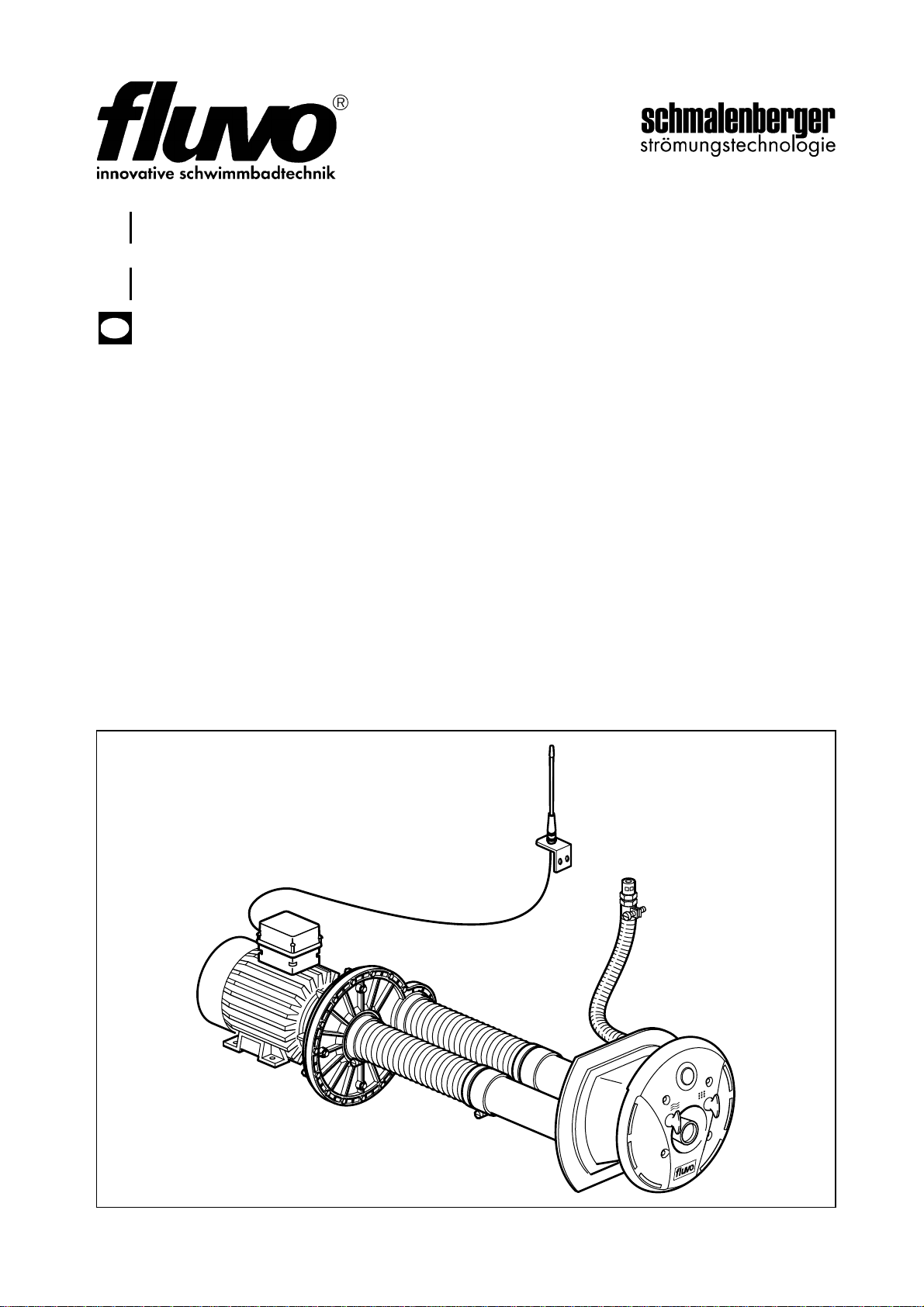
fig. 1
Overview of the Counter-current Sy-
stem
The counter-current system consists
of:
1. Pump kit
2. Assembly kit
3. Installation kit
The installation kit is always different
depending on the pool type.
There are 4 kinds of pool:
- Concrete-tile pool
- Concrete-liner pool
- Pre-fabricated pool
(steel, plastic or similar)
- Wood-liner pool
8360
OPERATOR‘S MANUAL
7
NTG700 rondo
Version:27213 - ESchmalenberger GmbH + Co. KG
D-72072 Tübingen / Germany
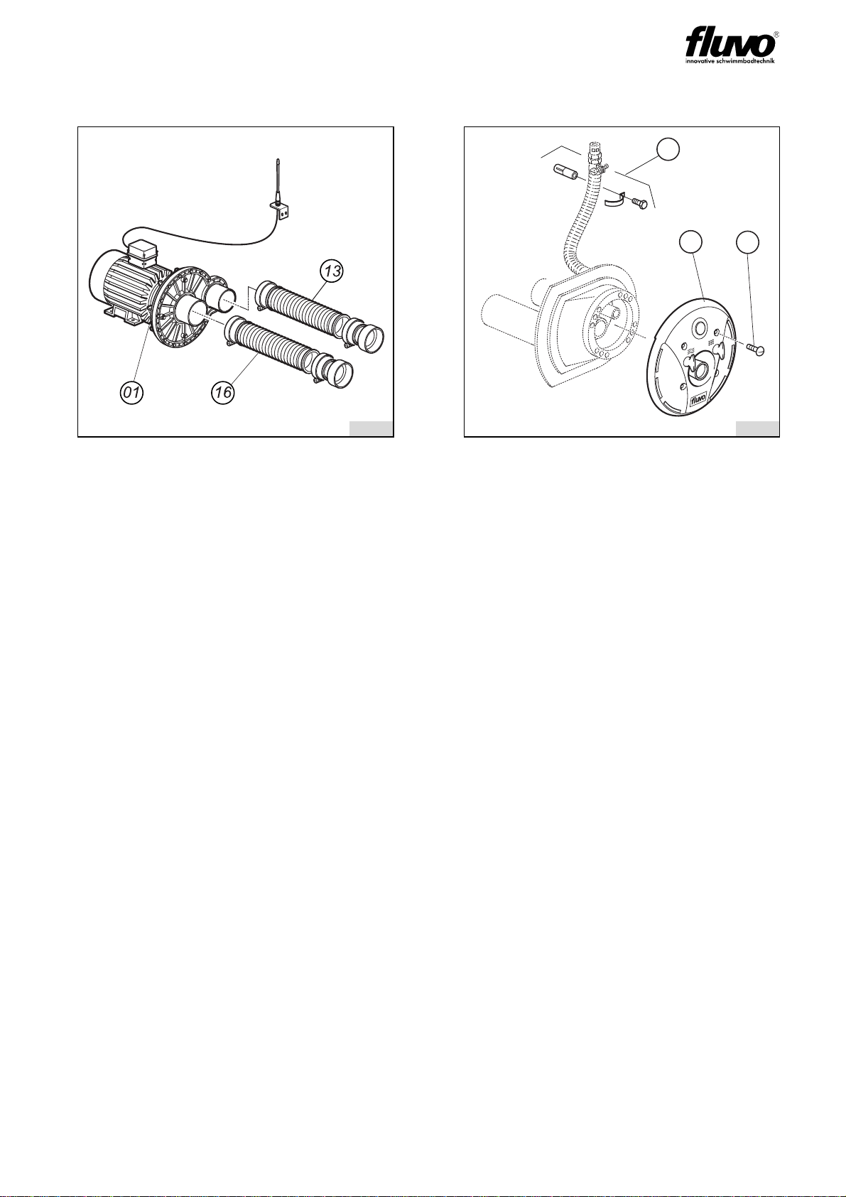
The item numbers correspond to the numbers in the parts list.
fig. 2 fig. 3
I - Pump kit
The pump kit consists of:
1. Pump assembly Item 01*
2. Suction hose Item 16
3. Pressure hose Item 13
*The pump kit is always identical no matter what
sort of pool it is intended for.
III - Assembly kit
The assembly kit consists of:
1. Face plate assembly Item 35
2. Mounting screws Item 90
3. Fixing bracket for
non-return air valve Item 56
8362
56
35 90
8332

OPERATOR‘S MANUAL
8NTG700 rondo
Version: 27213 - E
Schmalenberger GmbH+ Co. KG
D-72072 Tübingen / Germany
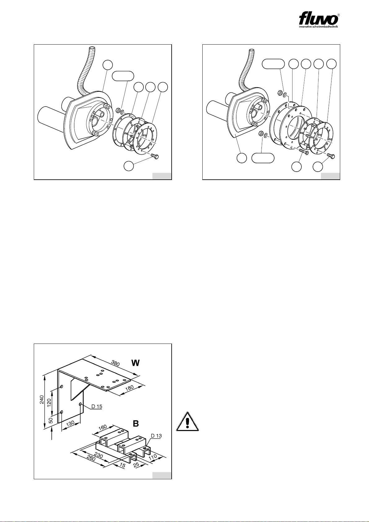
fig. 4 fig. 5
III - Installation kit / Concrete-tile pool
The installation kit consists of:
1. Housing Item K
The installation kit is concreted into the
concrete wall of the pool.
For details regarding installation, please
see section 4.
III - Installation kit for concrete-liner pool
The installation kit consists of:
1. Housing Item K
2. Clamp ring Item 72
3. Clamp gasket Item 34
4. Mounting screws Item 74
The installation kit is concreted into the
concrete wall of the pool.
Note: Parts 2 to 4 are delivered with the
face plate assembly.
K
8362 8363
K
32 72
74
OPERATOR‘S MANUAL
9
NTG700 rondo
Version:27213 - ESchmalenberger GmbH + Co. KG
D-72072 Tübingen / Germany
4 Installation Site Specifications and Installation
4.1 Base frames for the installation
fig. 6 fig. 7
III - Installation kit for pre-fabricated pool
The installation kit consists of:
1. Housing Item K
2. Clamp ring Item 22
3. Clamp gasket Item 39
4. Hold-ring Item 62
5. Mounting screws Item 74
6. Nuts and washers Pos. 26/27
For details regarding installation, please
see section 4.
III - Installation kit for wood-liner pool
The installation kit consists of:
1. Housing Item K
2. Clamp ring Item 22
3. Clamp gasket Item 39
4. Washer Item 68
5. Hold-ring Item 67
6. Mounting screws Items 63/74
7. Nuts and washers Items 64/65
84/85
For details regarding installation, please
see section 4.
fig. 8
There are two base frames available that
must be ordered separately to suit local
circumstances.
1. W= for wall mounting
2. B= for floor mounting
Warning! Risk of damage!
As the pumps are not self-priming, the in-
stallation must be under water level.
Make sure you take this into account du-
ring the installation planning phase.
26/83
K
62 39 22
74
8364
63 74
64/65K
84/83 68 67 39 22
8365
8338

OPERATOR‘S MANUAL
1 0 NTG700 rondo
Version: 27213 - E
Schmalenberger GmbH+ Co. KG
D-72072 Tübingen / Germany
4.2 Planning the pump pit
When planning a pump duct take into account:
1. Clear dimensions min. 600 x 600 x 600
2. Return connection min. 300 mm under the pool water level
3. Leakage water discharge pipe-end min. DN 40
4. Opening for cooling air min. 2x DN 125
5. Be sure to cover the pump pit if it is installed in the open air.
6. The position of the non-return air valve (L) must always be over the pool water level.
7. In case of leakage from the pump, a suitable water drainage must be provided!
8. The direct distance between the transmitter (S) and the aerial (33) must not exceed 1m!
4.3 Installation Preparations / Concrete pool
Tailor the installation kit:
Place the installation kit on the formwork board and transfer the bore holes. Bore the holes
into the pool-side formwork board (Pb). Mark out and cut holes into the outer formwork
board (P) for the suction and pressure supplies and the two hoses.
Screw the installation kit complete with the mounting protection film (C) tightly to the pool-
side formwork board (Pb).
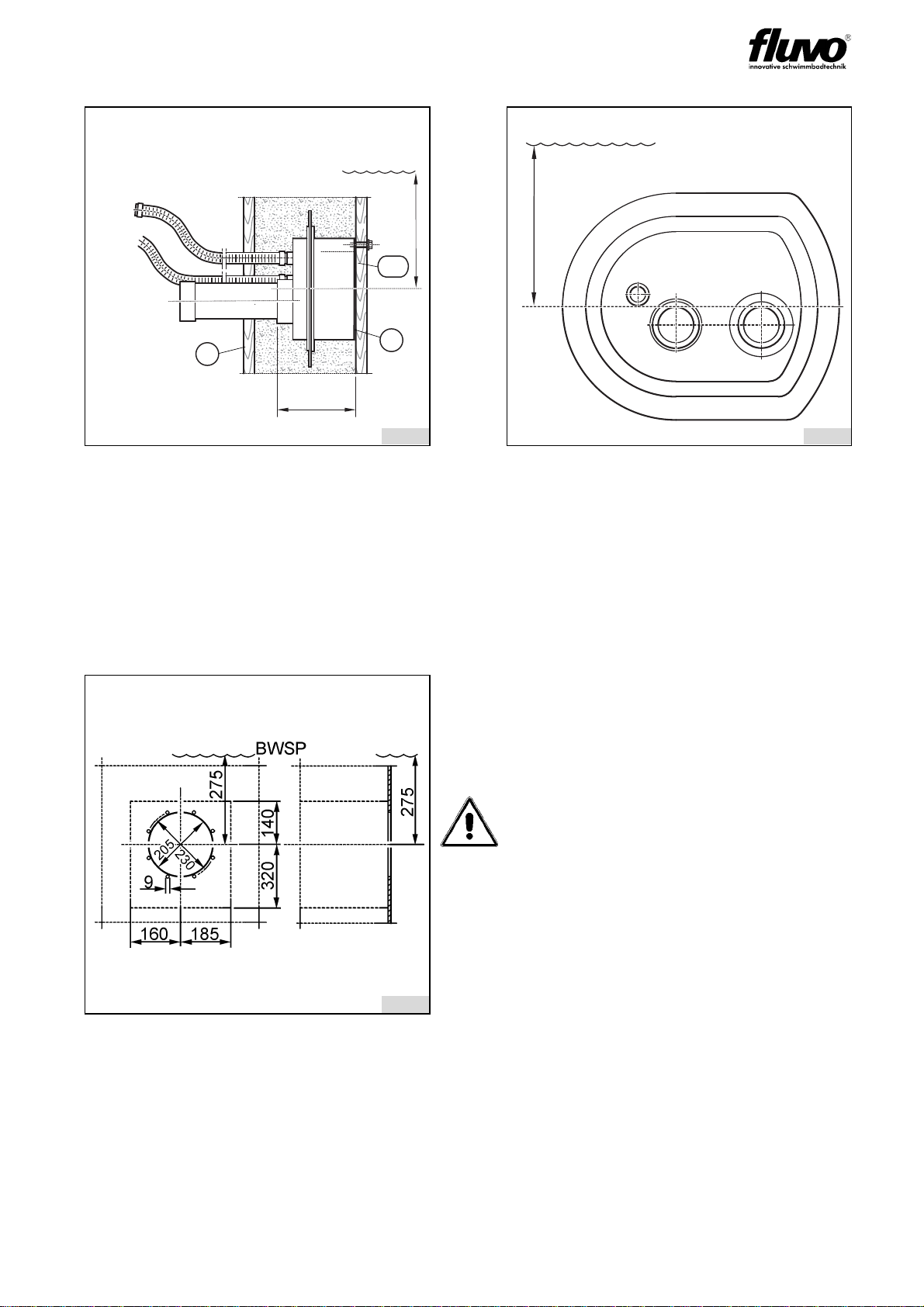
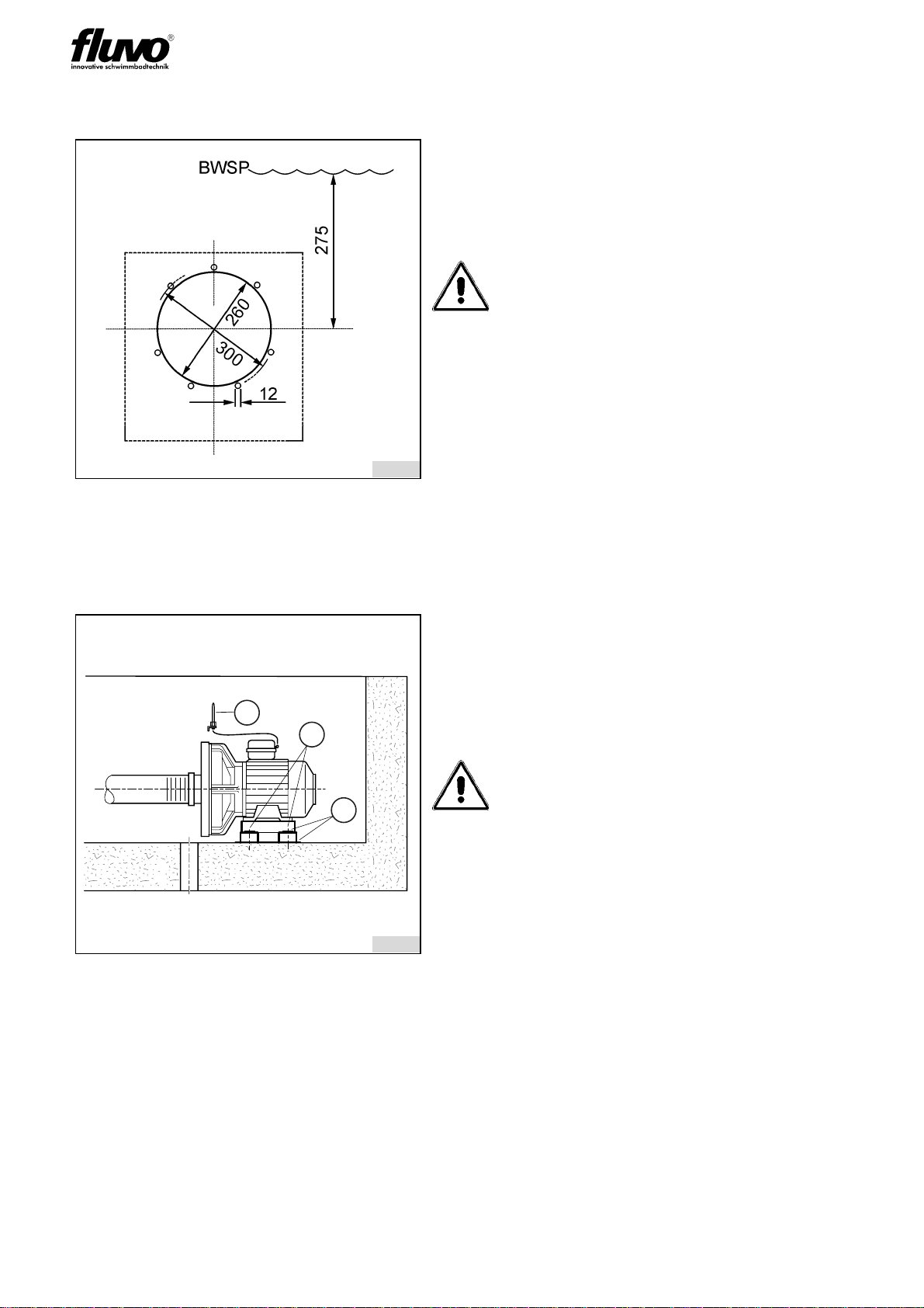
fig. 9: Cross-sectional view of the pump
pit fig. 10: Top view of the pump pit
BWSP Pool water level (PWL)
L Air valve
33 Aerial
S Transmitter
33 Aerial
Warning! Risk of damage!
1. The installation kit must be horizontal!
2. The distance between the centre of the installation kit and the water level
(BWSP) must be 275 mm.
8339
300
min. 1000 mm
min. DN 40
BWSP
160
L
33
8340
115
min. 1000 mm
min. 1500
350
600
S
33
OPERATOR‘S MANUAL
11
NTG700 rondo
Version:27213 - ESchmalenberger GmbH + Co. KG
D-72072 Tübingen / Germany
4.4 Installation Preparations / Pre-fabricated pool
fig. 11 fig. 12: Rear of the installation kit
C Mounting protection film
P Outer formwork board
PbPool-side formwork board
1. Pressure pipe (DN 50)
2. Suction pipe (DN 65)
3. Air supply to the non-return air
valve
fig. 13: Boring diagram
Tailor the installation kit
Apply the cavity Ø 205 and the mounting
holes Ø 9 to the pool wall.
Warning! Risk of damage!
The hold-ring (62) must be used as a
template.
For backfilling the pool ensure that there
is a cavity at least the size of the dotted
lines.
8366
275
152
BWSP
P
P
B
C
8367
275
BWSP
12
3
8308
OPERATOR‘S MANUAL
12 NTG700 rondo
Version: 27213 - E
Schmalenberger GmbH+ Co. KG
D-72072 Tübingen / Germany
4.5 Installation Preparations / Wood-liner pool
4.6 Installation - general
Place the base frame in the desired position. Fasten the base frame with 4 screws (S).
fig. 14: Boring diagram
Tailor the installation kit
Apply the cavity Ø 260 and the mounting
holes Ø 12 to the pool wall.
Warning! Risk of damage!
The hold-ring (68) must be used as a
template.
Take note of the asymmetrical position of
the holes!
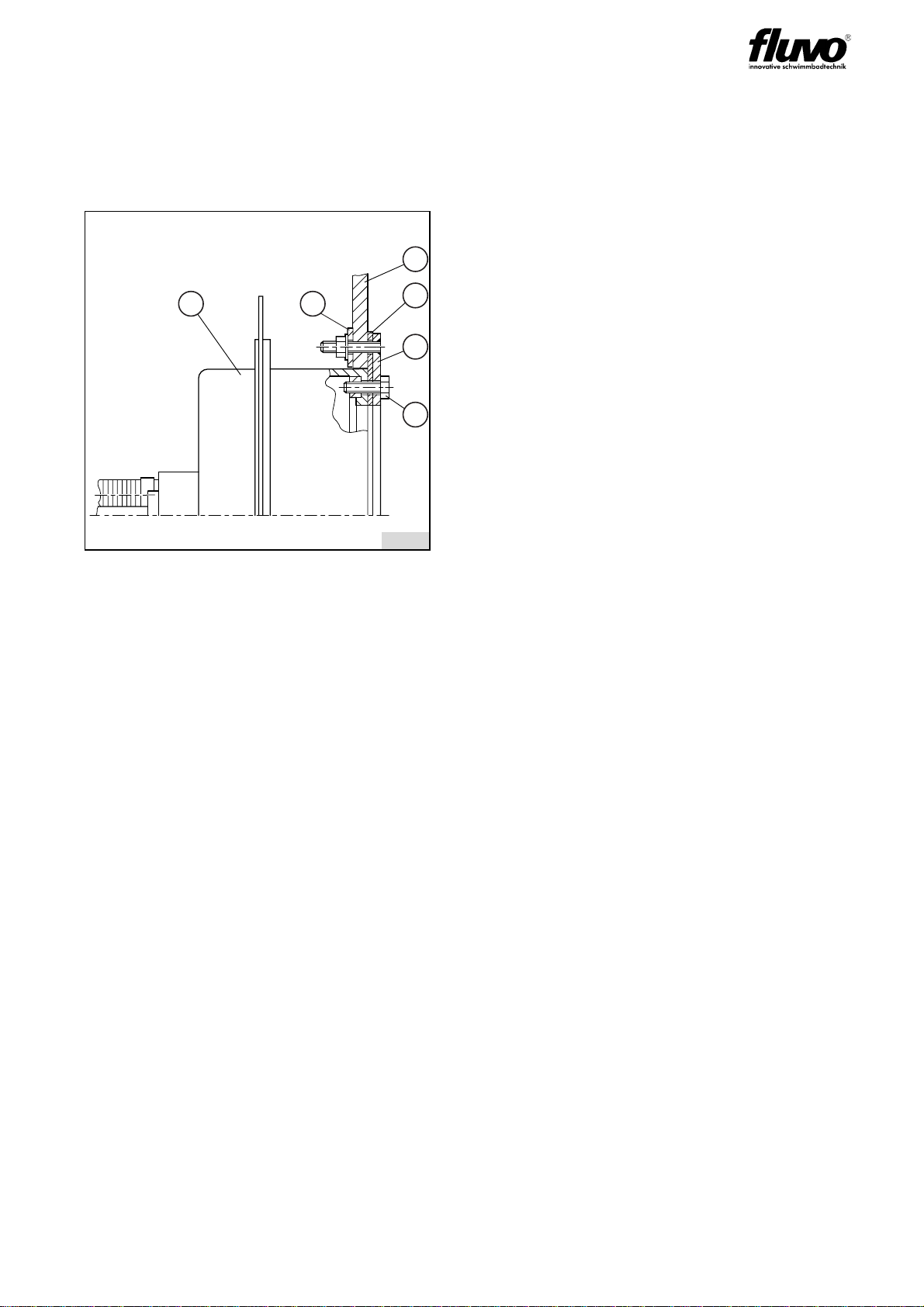
fig. 15
I Insulation
SScrew
33 Fixing bracket including aerial
Warning! Mortal danger!
If the motor is to be installed with a metal
supporting foot, then it must be fastened
insulated against the floor to avoid the
transfer of spurious voltages to the
device and swimming pool water.
8309
8343
S
I
33
OPERATOR‘S MANUAL
13
NTG700 rondo
Version:27213 - ESchmalenberger GmbH + Co. KG
D-72072 Tübingen / Germany
4.7 Installation kit Installation / Pre-fabricated pool
Mount the clamp ring (22) with the clamp gasket (39) and the hold-ring (62) to the pool wall.
The sealing contact faces must be clean and smooth.
Then mount the housing (K) on the clamp ring (22) with the screws (74).
fig. 16
BPoolwall
KHousing
22 Clamp ring
39 Clamp gasket
62 Hold-ring
74 Hexagon screw
8368
B
K62 32
22
74

OPERATOR‘S MANUAL
14 NTG700 rondo
Version: 27213 - E
Schmalenberger GmbH+ Co. KG
D-72072 Tübingen / Germany
4.8 Installation kit Installation / Wood-liner pool
Mount the hold-ring (67) with the distance washer (68) to the pool wall.
Hang in the liner (L). Fasten the liner (L) and the clamp gasket (39) together with the clamp
ring (22) and cut out the liner (L). Then mount the installation kit (92) on the clamp ring (22)
with the screws (74). See also detail X in fig. 18.
fig. 17 fig. 18: Detail X
BPoolwall
KHousing
22 Clamp ring
39 Clamp gasket
63 Countersunk screw
64 Distance washer
67 Hold-ring
68 Distance washer
74 Hexagon screw
84 Hexagon nut
92 Installation kit
92 Installation kit
8369
275
X
260
BWSP
B
K
8370
Detail "X"
B
68
K
67
39
74
22

OPERATOR‘S MANUAL
15
NTG700 rondo
Version:27213 - ESchmalenberger GmbH + Co. KG
D-72072 Tübingen / Germany
4.9 Pump Kit Installation
Mount the pump free of all tension with the hexagon screws M8 (S) on the base frame.
4.9.1 Connection to the pool
Stick the adaptors (14+17) to the pipe connection on the housing (K). Alternatively, by
using pipework, mount to the pump-side end of the pipework.
Warning!
1. Do not use any vibration dampers between the pump and the base frame.
2. If the pipework (R) to the pump is longer than 6 m then the nominal width
must be increased.
-Suction side from DN 65 to a min. of DN 80
-Pressure side from DN 50 to a min. of DN 65.
3. Then always mount the adaptors (V) on the pump body.
fig. 19
R Pipework
S Hexagon screws M8
V Adaptor
fig. 20
14 Return connection
17 Suction connection
KHousing
Warning!
Always be sure to lay the pipework using
bends and not angles to keep the pipe
resistance to a minimum.
8358
8371
K
17
14

OPERATOR‘S MANUAL
1 6 NTG700 rondo
Version: 27213 - E
Schmalenberger GmbH+ Co. KG
D-72072 Tübingen / Germany
4.9.2 Connection to the pump
Connect the hose lines (13 pressure side + 16 suction side) to the pump body. Use the
corresponding air pipe clamps (12.1, 12.2) on both sides for this.
4.9.3 Installing the aerial
Mount the aerial (33) with the fixing bracket (21) parallel to the pool wall close to the trans-
mitter (S).
Keep the distance between the transmitter (S) in the face plate assembly and the aerial
(33) as short as possible.
fig. 21
01 Motor
12.1 Air pipe clamp
12.3 Air pipe clamp
13 Hose line pressure side
16 Hose line suction side
Warning!
Make sure that the connections from the
body of the pump to the installation kit /
pipework are as nearly aligned as is
possible.
The hose lines must always be attached
to the pump on the one side
(compensator function), see fig. 21.
fig. 22
S Transmitter
21 Fixing bracket
33 Aerial
Warning!
The direct distance between the
transmitter (S) and the aerial (33) must
not exceed 1m!
The aerial must not be put into the
protective hose of the installation kit.
8347
8383
OPERATOR‘S MANUAL
17
NTG700 rondo
Version:27213 - ESchmalenberger GmbH + Co. KG
D-72072 Tübingen / Germany
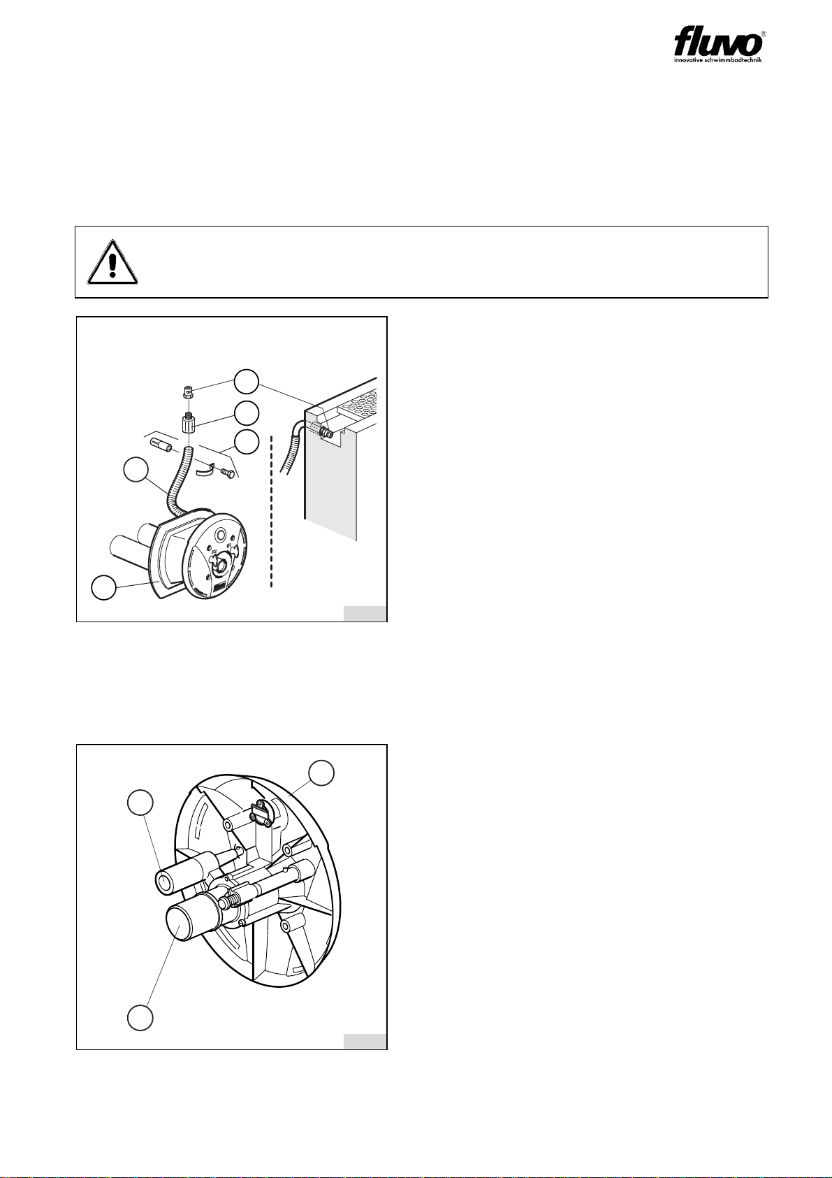
4.9.4 Non-return air valve Installation
Connect the non-return air valve (28) and the air line hose tail (29) to the air hose (T). Warm
the air hose (T) up prior to connecting. Fasten with the air pipe clamp (52).
Fasten the non-return air valve (28) with the fixing bracket (56) to the pool wall or similar.
In the case of a ground level overflow, place the non-return air valve (28) in the duct, see
fig. 23, detail B.
4.10 Mounting the face plate assembly
Figure 24 shows the rear of the face plate assembly.
Warning!
For the positioning of the non-return air valve (28) be sure to observe the de-
tails stated in section 4.2, Planning the pump pit.
fig. 23
T Air hose
20 Installation kit
28 Non-return air valve
29 Air line hose tail
30 Hose tail
52 Air pipe clamp
56 Fixing bracket
fig. 24
D Return connection
L Air connection
35 Face plate assembly
8373
AB
28
29
56
T
20
8317
35
L
D

OPERATOR‘S MANUAL
1 8 NTG700 rondo
Version: 27213 - E
Schmalenberger GmbH+ Co. KG
D-72072 Tübingen / Germany
4.10.1 Face plate assembly Installation / Concrete-tile pool
Remove the mounting protection film (C). Put on the face plate assembly (35), this allows
the pressure connection (D) and air connection (L) to slide into one another. Fasten to the
installation housing (99) with the screws (90.1).
4.10.2 Face plate assembly Installation / Concrete-liner pool
Remove the mounting protection film (C). Place the clamp gasket (32) between the instal-
lation housing (99) and the liner (L) and screw the clamp ring (72) to the installation housing
(99) using the screws (74). The sealing contact faces must be clean and smooth. Now cut
out the pool liner (L).
Put on the face plate assembly (35), this allows the pressure connection (D) and air con-
nection (L) to slide into one another. Fasten to the clamp ring (72) with the screws (90.2)
fig. 25
C Mounting protection film
K Installation housing
35 Face plate assembly
90.1 Screw
fig. 26
C Mounting protection film
K Installation housing
32 Clamp gasket
35 Face plate assembly
72 Clamp ring
74 Screw
90.2 Screw
8349
C
35
K
90.1
8375
C
35
7472
K
39
90.2
OPERATOR‘S MANUAL
19
NTG700 rondo
Version:27213 - ESchmalenberger GmbH + Co. KG
D-72072 Tübingen / Germany
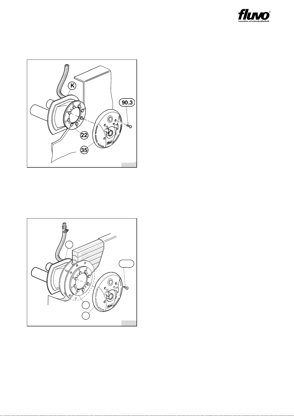
4.10.3 Face plate assembly Installation / Pre-fabricated pool
Put on the face plate assembly (35), this allows the pressure connection (D) and air con-
nection (L) to slide into one another. Fasten to the clamp ring (22) with the screws (90.3).
4.10.4 Face plate assembly Installation / Wood-liner pool
Put on the face plate assembly (35), this allows the pressure connection (D) and air con-
nection (L) to slide into one another. Fasten to the clamp ring (22) with the screws (90.3).
fig. 27
K Installation housing
22 Clamp ring
35 Face plate assembly
90.3 Screw
fig. 28
K Installation housing
22 Clamp ring
35 Face plate assembly
90.3 Screw
8376
8377
35
22
K
90.3

OPERATOR‘S MANUAL
2 0 NTG700 rondo
Version: 27213 - E
Schmalenberger GmbH+ Co. KG
D-72072 Tübingen / Germany
5 Electrical Connections
5.1 Electrical Connections - general
The electrical connections to the counter-current swimming system must be carried out by
a specialised company in the electrical engineering branch approved by the local energy
provider, taking into account the technical connection requirements.
Please observe:
• The mains power connection must be a fixed connection.
• Under no circumstances must there be any conducting connection between the metal
parts of the motor and the water.
• An earth leakage circuit breaker (nominal fault current £30 mA) must be fitted to the
mains power connection.
• The mains power supply cable must be equipped with an all-pole separator with a con-
tact opening of 3 mm.
• At the marked connection terminal (at the foot of the motor or next to the terminal box)
an equalising potential with a cross-section of 10 mm² must be fitted.
• The counter-current swimming system must only be operated provided that the termi-
nal box lid is closed!
5.1.1 Direction of rotation check
In the case of 3~ motors the direction of rotation must be the same as the direction of ro-
tation arrow on the blower cover of the counter-current swimming system .
Warning! Mortal danger!
The connections must be carried out by a qualified electrician.
For this refer to the TAB of the EVS, the VBG 4(§3) and DIN VDE 1000-10/
1995-5, for example.
The relevant DIN VDE (Association of German Engineers) regulations
0100 and in the case of explosion protection 0165 must be observed.
If the installation is not carried out properly, there is a risk of getting electric
shocks!
Warning!
Compare the available power supply voltage with the details on the motor’s
factory plate and select the appropriate switching.
We recommend the use of a motor protection facility. Explosion protected mo-
tors, increased safety (Ex)–e and temperature class T3, must always be con-
nected in accordance with DIN VDE 0170/0171 via a motor protection switch.
Connect the motor in accordance with the circuit diagrams in sections5.2and
5.3.
Warning!
Check by rapidly switching on and off.
If the direction of rotation is wrong for 3~ motors, change any two phases L1,
L2 or L3 of the power supply in the motor terminal box over.
Table of contents
Other FLUVO Lighting Equipment manuals


