ChargePoint Express 250 User manual

Express 250
Surface Conduit Entry Kit
Symbols Used in This Document ............................... 3
Introduction ................................................................... 4
Before You Begin......................................................... 4
Tools and Materials...................................................... 5
Check Site Readiness .................................................. 6
Check the SCE Kit Contents ....................................... 8
Prepare the Express 250............................................. 8
Install Surface Mount Anchor Bolts........................... 9
Anchor and Label the Station ....................................11
Install the SCE Box Base and Box Cover ..................11
Continue Normal Installation ....................................15
ChargePoint Charging Stations
2
IMPORTANT SAFETY INSTRUCTIONS:
SAVE THESE INSTRUCTIONS
Product Disposal
To comply with Directive 2012/19/EU of the European Parliament and of the Council of 4 July 2012 on
waste electrical and electronic equipment (WEEE), devices marked with this symbol may not be
disposed of as part of unsorted domestic waste inside the European Union. Enquire with local authorities
regarding proper disposal. Product materials are recyclable as marked.
No Accuracy Guarantee
Commercially reasonable efforts were made to ensure that the specifications and other information in this manual are
accurate and complete at the time of its publication. However, the specifications and other information in this manual are
subject to change at any time without prior notice.
Copyright and Trademarks
©2013-2020 ChargePoint, Inc. All rights reserved. This material is protected by the copyright laws of the United States
and other countries. It may not be modified, reproduced or distributed without the prior, express written consent of
ChargePoint, Inc. CHARGEPOINT is a U.S. and European Union registered trademark and service mark of ChargePoint,
Inc. and cannot be used without the prior written consent of ChargePoint.
WARNING:
1. Read and follow all warnings and instructions before installing and operating the ChargePoint®
Charging Station. Install and operate only as instructed. Failure to do so may lead to death, injury, or
property damage, and will void the Limited Warranty.
2. Only use licensed professionals to install your ChargePoint charging station and adhere to all national
and local building codes and standards. Before installing the ChargePoint® charging station, consult with a
licensed contractor, such as a licensed electrician, and use a trained installation expert to ensure
compliance with local building and electrical codes and standards, climate conditions, safety standards, and
all applicable codes and ordinances. Inspect the charging station for proper installation before use.
3. Always ground the ChargePoint charging station. Failure to ground the charging station can lead to risk
of electrocution or fire. The charging station must be connected to a grounded, metal, permanent wiring
system, or an equipment grounding conductor shall be run with circuit conductors and connected to the
equipment grounding terminal or lead on the Electric Vehicle Supply Equipment (EVSE). Connections to the
EVSE shall comply with all applicable codes and ordinances.
4. Install the ChargePoint charging station on a concrete pad using a ChargePoint approved method.
Failure to install on a surface that can support the full weight of the charging station can result in death,
personal injury, or property damage. Inspect the charging station for proper installation before use.
5. This charging station is not suitable for use in or around hazardous locations, such as near flammable,
explosive, or combustible materials.
6. Do not use this product if the enclosure, EV cable, or the EV connector is broken, cracked, open, or
shows any other indication of damage.
7. Do not put fingers into the electric vehicle connector.
8. This device should be supervised when used around children.
Important: Under no circumstances will compliance with the information in this manual relieve the user of
his/her responsibility to comply with all applicable codes or safety standards. This document describes the
most commonly-used installation and mounting scenarios. If situations arise in which it is not possible to
perform an installation following the procedures provided in this document, contact ChargePoint, Inc.
ChargePoint, Inc. is not responsible for any damages that may result from custom installations that are
not described in this document or for any failure to adhere to installation recommendations.

Express 250
3
Symbols Used in This Document
This guide and product use the following symbols:
DANGER: Risk of electric shock.
WARNING: Risk of personal harm or death.
CAUTION: Risk of equipment or property damage.
Important: Crucial step for installation success.

ChargePoint Charging Stations
4
Introduction
This document describes how to install an Express 250 DC fast charging station ins situations where the site
cannot pour a new concrete pad or run conductors underground. The Surface Conduit Entry (SCE) kit allows
surface drilling and epoxy installation of anchor bolts, as well as a rear conduit entry box for conductors to
enter the station through surface wireways. The SCE kit supports both Standalone and Paired installations.
The SCE kit also supports adding above-ground conduit to pair an already-installed Standalone station with
another Express 250 for shared DC output.
Installing an Express 250 using the SCE kit requires one ChargePoint Certified Installer and about 2.5 to 3
hours to complete (not including epoxy cure time). This time estimate includes the full charging station
installation, including the applicable steps described in the Express 250 Installation Guide. If this is a Paired
installation, allow an additional hour. This time estimate does not include the time needed to pull cables.
Note: This document is a supplement to the normal charging station installation described in the Express
250 Installation Guide that ships with the station. Ensure all installation instructions from that guide are
followed except where this guide deviates.
Note: Shunt trip wiring is normally a feature of the Express 250, but is not required for operation. If shunt
trip wiring will be used, run a wireway for the low voltage shunt trip wires that is separate from the AC
conductor wireway.
Before You Begin
Note: For assistance, go to chargepoint.com/support and find your region’s technical support number.
DANGER: RISK OF SHOCK. Before performing this procedure, follow standard practice and local
code to de-energize the circuit designated for each Express 250 at the service panel and lock
out/tag out the disconnect before proceeding. Use a multimeter to test that power is off. Keep
power off for this circuit until all cover panels are correctly reinstalled and the work scope is
completed. FAILURE TO FOLLOW THESE INSTRUCTIONS CAN RESULT IN SERIOUS INJURY OR
LOSS OF LIFE.
Important: You must be a licensed electrician and complete an online training course to become a
ChargePoint certified installer, and to get a login for ChargePoint. If you do not complete this
training, you will be unable to complete the installation process. Go to: chargepoint.com/installers
or chargepoint.com/eu/installers
CAUTION: Do not use power tools during installation or servicing. Over-torquing can damage the
equipment.
CAUTION: Do not install the charging station in inclement weather. If you must complete the
installation in rain or wind, you must use a weather-proof shelter that covers all boxes and
components.

Express 250
5
Tools and Materials
For an SCE installation, the installer must bring:
•All tools and materials mentioned in the Express 250 Charging Station Installation Guide (if installing a
new station) or Express 250 Pairing Retrofit Guide (if upgrading a Standalone station to be Paired).
Online copies of both are available at chargepoint.com/installers or chargepoint.com/eu/installers
•Surface wireways:
•2 in trade size for AC cable
•3 in trade size for DC cable (if Paired)
•3/4 in trade size for Ethernet Cat5 (if Paired)
•3/4 in trade size for shunt trip (if used)
•Conduit elbows sized to each size wireway
•Tools for cutting, assembling, and securing wireways
•Sheet metal drill with drill bits for wireway sizes listed above, as needed (pilot holes provided)
•Concrete drill, level feature recommended
•25 mm (1 in) and 6 mm (1/4 in) concrete bits
•25 mm (1 in) rebar bit if needed
•24 mm (15/16 in) open ended wrench
•Flathead screwdriver
•750 ml of epoxy with bonding strength of 11.7 MPa minimum, compressive strength of 82.7 MPa
minimum, and tensile strength of 49.3 MPa minimum, such as Hilti HIT-RE 500 V3 (normal cure time),
Hilti HY-200 (fast curing), or similar
Note: Different epoxy types have different cure times at various temperatures. Check local temperatures
for the site in advance to help choose an appropriate epoxy.
•Cable puller or fish tape
•Vacuum and/or brush
•Marker
•Isopropyl wipes
•Paper towels
Important: Read the Express 250 Charging Station Installation Guide, Express 250 Charging Station
Site Design Guide, and site drawings to source and bring the correct AC conductors (required),
shunt trip wiring (optional), DC conductors and lugs (Paired installations only), and Ethernet wiring
(Paired installations only).
Important: If the Express 250 will be paired, check the serial number on the rear surface just under
the cable swing arms. For North America stations with SNs prior to 1929xxxx, or EU/UK SNs prior
to 2003xxxx, the station also requires a Pairing Upgrade Kit. Contact ChargePoint for the kit and
the installation guide for that configuration.

ChargePoint Charging Stations
6
Note: This product is compatible with the
Express 250 Adapter. If the station has a
slightly raised black or silver base below the
cover panels, as shown on this image, break
off the two front tabs on the SCE box base
along their scored edges.
Note: SCE installations require a larger rear
clearance than a normal Express 250
installation, to allow room for the SCE and
wireways. Wireways must enter the SCE on its
rear face. Conductor bend radius does not allow wireways to enter the SCE from its sides.
Check Site Readiness
Before beginning work, check that the site meets the basic requirements outlined below, as illustrated in the
following image. Measurements are listed in mm (in).
•The panel breaker serving the charging station matches the site drawing requirements depending on
local code and the type of installation: 62.5 kW Standalone, 125 kW Paired, or 50 kW de-rated (when
replacing a previous, lower-amperage system).
•The smooth, level concrete has been approved by a structural engineer for the Express 250 dimensions
and weight, OR conforms to these general specifications*:
•At least 305 mm (12 in) deep (or deep enough to be 305 mm (12 in) below the frost line)
•At least 1296 mm (51 in) on each side
•Contains #4 rebar top and bottom 305 mm (12 in) on center
•Concrete 2500 PSI minimum
* These pad specifications are applicable in most conditions, as described in the Express 250 Site Design
Guide. In some extreme conditions, a larger pad would be required.
•Charging station sites are positioned so that each station is centered on a parking space (unless
curbside), with the front of the station facing the vehicle. (This maximizes cable reach.)
•The cellular signal strength at the station location has been tested and is consistently strong. If RSRQ is
measured at -10 dB or better, then RSRP can be -90 dBm or better. If RSRQ cannot be measured or is
not adequate, RSRP must be -85 dBm or better.
•The service clearance of open space (not necessarily at system grade) extends a minimum of 610 mm
(24 in) beyond the station in front, 2156 mm (84.8 in) side to side centered on the station, and 305 mm
(12 in) above the station (image callout a, below). See the images below for rear clearance depending
on configuration.
•The front of the station has 352 mm (14 in) of space at grade from the front right anchor, extending
1700 mm (67 in) to the left, without any permanent obstructions (bollards, wheel stops, etc.) (image
callout b).

Express 250
7
If the conduit runs from the back of the SCE to the side(s), with rigid wireway elbows:
•The rear conduit clearance at grade is 700 mm (27.6 in)
•The recommended extra rear service clearance of open space (not necessarily at grade) is 300 mm
(12 in) for servicing the conduit, for a total of 1005 mm (39.6 in) from the front anchor
If the conduit runs from the back of the SCE straight back:
•The rear conduit clearance at grade is 550 mm (21.7 in)
•The recommended extra rear service clearance of open space (not necessarily at grade) is 300 mm
(12 in) for servicing the conduit, for a total of 855 mm (33.7 in) from the front anchor
1305
(51.4)
280
(11)
1700
(67)
352
(14)
63 (2.5)
851
(33.5)
610
(24)
1005
(39.6)
700
(27.6)
1305
(51.4)
280
(11)
1700
(67)
352
(14)
63 (2.5)
550
(21.7)
610
(24)
855
(33.7)
851
(33.5)
ChargePoint Charging Stations
8
If the site does not meet these basic requirements, contact ChargePoint before continuing.
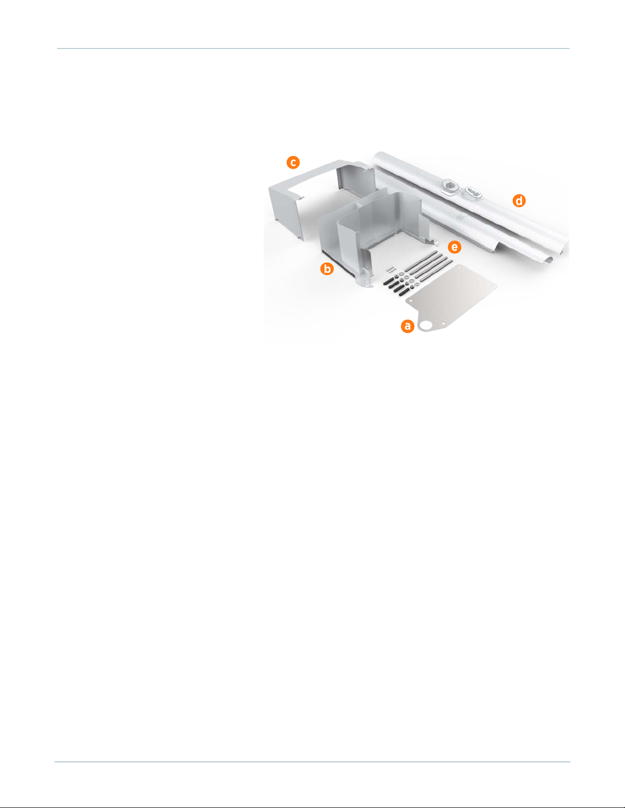
Check the SCE Kit Contents
Check the contents of the SCE Kit before
beginning work. The SCE Kit might arrive
in multiple boxes. The full kit includes:
a. Surface mount plate
b. Box base
c. Box cover
d. Left and right side extrusions with
SCE cutouts (x2)
e. Fasteners:
•Box base screws (x8)
•M16 x 300 Hilti anchor bolts,
304.8 mm (12 in) long (x4)
•M16x13x2 hex nuts (x8)
•5/8 in ASTM F436 washers (x8)
Prepare the Express 250
Determine whether you are installing a new Express 250 station to be completely surface mounted, or you
are adding above-ground conduit to pair a Standalone station with another Express 250 for shared DC
output.
If you are installing a NEW station:
1. Receive the Express 250 station and its Power Modules at the site.
2. Follow the directions in section 1 of the Express 250 Charging Station Installation Guide to familiarize
yourself with the process, crate contents, and required tools and materials.
3. Begin installation with the next section, "Install Surface Mount Anchor Bolts" on page 9.
If you are UPDATING a station:
1. Receive the Express 250 Pairing Kit at the site.
2. Follow the directions in section 1 of the Express 250 Pairing Retrofit Guide to familiarize yourself with
the process, crate contents, and required tools and materials.
3. Power off the station and remove all cover panels as described in the Express 250 Pairing Retrofit Guide.
Note: Earlier stations had grounding straps on the Power Modules and their holders. If you are pairing an
existing station, you must replace these with the EMI shields included in your Pairing Kit. The straps are
not sufficient for paired stations.
4. Begin work in this guide with the section "Install the SCE Box Base and Box Cover" on page 11.

Express 250
9
Install Surface Mount Anchor Bolts
1. Follow standard practice and local code to de-energize the applicable circuit and lock out/tag out the
disconnect before proceeding. Use a multimeter to test that power is off.
2. Place the surface mount plate at the proposed
location. Align the large left hole with AC conduit if
present (for example, when replacing an older
station). Check that the station placement on the pad
meets site requirements.
3. Use a marker to mark the locations for the Express
250 anchor bolts. Remove the surface mount plate.
4. Use the 6 mm (1/4 in) concrete drill bit to drill each
pilot hole about 51 mm (2 in) deep. The holes must
be parallel to each other and perpendicular to grade.
5. Use a vacuum or brush to clean the dust from the
holes.
6. Use the 25 mm (1 in) concrete drill bit to drill each
anchor hole a minimum of 229 mm (9 in) deep.
Anchor bolts must have 127 mm +/- 12.7 mm (5 in +/-
1/2 in) above grade.
7. Place the surface mount plate on the ground again.
Verify that the new holes for the Express 250 align
with the holes in the surface mount plate.
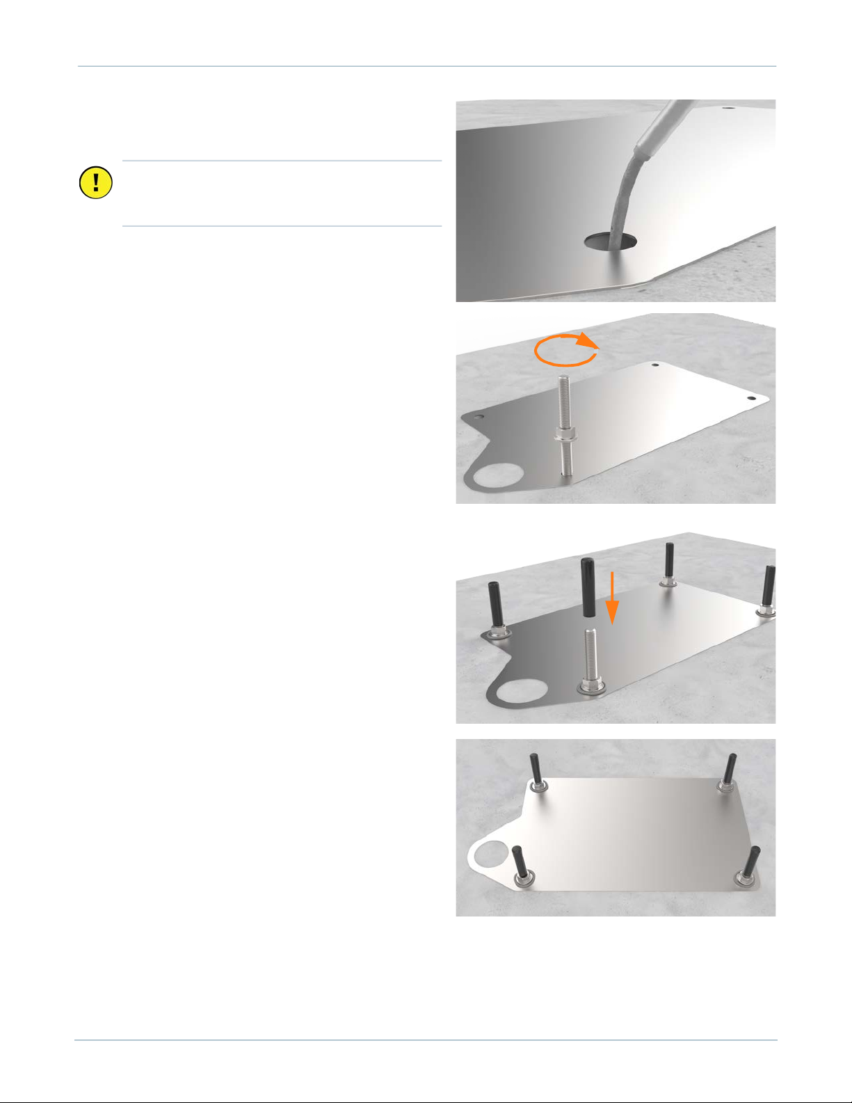
8. Thread a washer and a nut onto each anchor bolt, so that the measurement
from the top of the nut to the top of the bolt is 76 mm (3 in).
9. Put a piece of tape above each nut to prevent it from floating upward when
rotating the bolt into the epoxy later.
10. Prepare the epoxy. Ensure the applicator is dispensing correctly mixed epoxy
before beginning work (for example, the Hilti epoxy is white when unmixed
and grey when mixed).
Important: Ensure the rear clearance leaves
room for the conduit runs and for service
clearance.
76 mm
(3 in)
ChargePoint Charging Stations
10
11. Fill the first anchor bolt hole with epoxy until the
epoxy is about 44.5 mm (1.75 in) from the top of the
hole.
12. Insert the mounting bolt into the hole. Rotate the
mounting bolt as you insert it to draw epoxy into the
threads. Lift the anchor bolt again to see how close
to the surface the epoxy has filled. If the epoxy is
below grade level, add enough to fill the hole to
grade level. Use paper towels to wipe up any excess.
13. Measure the nut distance from the top of each bolt
again and adjust if needed. These nuts help secure
the surface mounting plate to the concrete and
should be flush against the base when installed.
14. If the Express 250 station will not be immediately
installed, insert a protective plastic cap over the bolt.
15. Use a level to check that each anchor bolt is plumb. If
needed, adjust while the epoxy is still setting.
16. Repeat the above epoxy steps for each of the other
three anchor bolts.
17. Stop. Allow the epoxy to cure for the initial cure time
listed on the epoxy, before beginning to install the
Express 250.
Note: If desired, use this time for measuring, cutting, and
fastening wireways to run conductors to the rear of the
station.
Important: Continue immediately to the next step
because the epoxy sets within about eight
minutes.

Express 250
11
Anchor and Label the Station
1. Check that the epoxy has set completely.
2. Torque all four nuts to 94.9 Nm (70 ft-lbs).
3. Follow the instructions in the Express 250 Installation Guide from the beginning of the guide to the end
of the section “Mount and Secure the Express 250”. The station should now be mounted on the anchor
bolts, leveled, and secured with the anchor washers and nuts.
4. Stop before connecting the AC wiring.
5. If required, adjust the ratings with a new label over
the existing ratings line, just below the swing arms
in the back:
a. If the Express 250 is being connected to wiring
and a breaker of 80 A, affix the 50 kW ratings label
to the station
b. If the Express 250 is being paired, affix the 125
kW label to the station
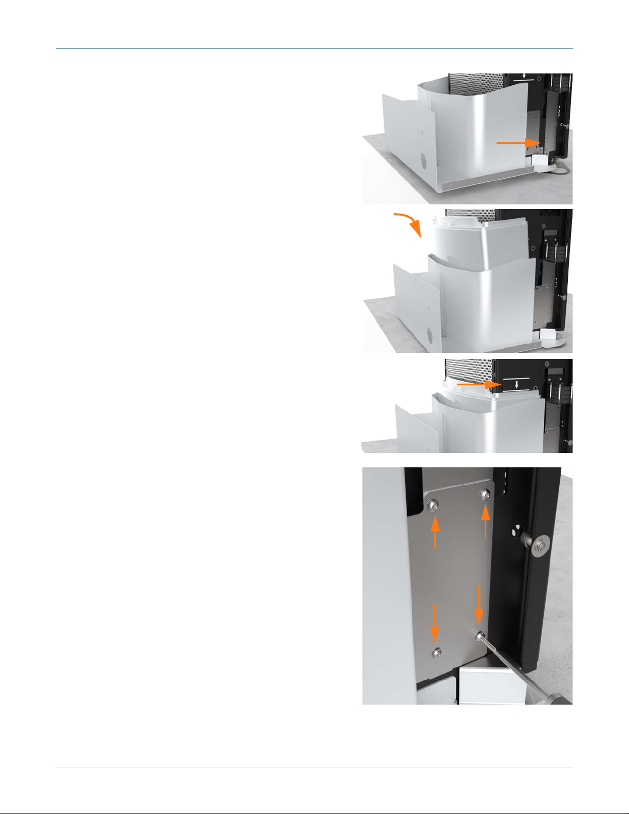
Install the SCE Box Base and Box Cover
1. Use a T25 Torx to remove the rodent guard L-brackets on
each side of the station, below the AC and DC wiring
terminals.
Important: The station should rest on the leveling nuts, not on the surface mount plate.
ChargePoint Charging Stations
12
2. Install the rear EMI shield:
a. Position the rear EMI shield (a) over the closed Power
Module holder, the drain hose, and the cooling controller cover
(b). Ensure the cutout on the long edge is on the right side,
leaving the sensor wire clear.
b. Use a T20 Torx to remove the two screws (c) that align with
the top EMI shield tabs. Discard the star washers beneath
them, if present.
c. Use isopropyl wipes to clean the frame grounding locations
and both sides of the rear EMI shield tabs.
d. Use a T20 Torx to reinstall the top screws with an M5 flat
washer from the installation kit to secure the top tabs of the
shield on each side.
e. Use a T25 Torx, an M5 screw, and an M5 washer to attach the
rear EMI shield to each middle and bottom grounding location
on the rear of the frame (d). Torque to 4 Nm (35 in-lbs).
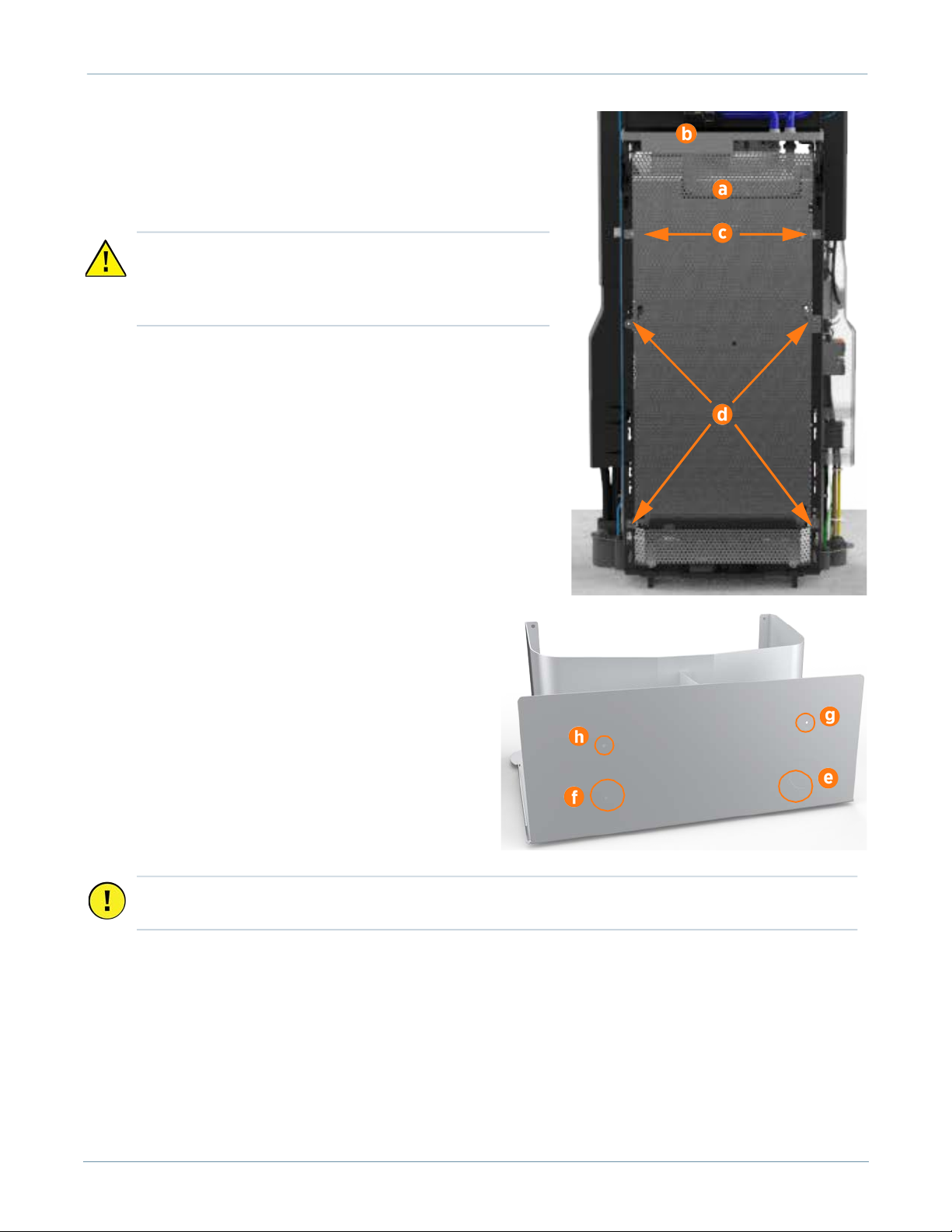
3. Loosen the captive screws along the bottom edges
of the SCE to release the cover from the base. Set the
cover aside.
4. Based on the provided pilot holes, use a sheet metal
drill bit to create the circle in the rear face of the box
base for AC (e). Drill out the circle for DC only if the
station will be paired (f).
5. If the station will have shunt trip wiring (g) or
Ethernet (h), use a 45 mm (12/16 in) core bit to drill
the hole(s) based on the provided pilot holes.
CAUTION: If the top edge of the EMI shield risks contact
with the wiring below the cooling controller or the drain
hose, pad the edge of the shield with electrical or duct
tape to prevent abrasion.
Important: Ensure the locations of the shunt trip and Ethernet holes do not interfere with routing
wireway elbows and conduit. Calculate height clearance for all wireways.
Express 250
13
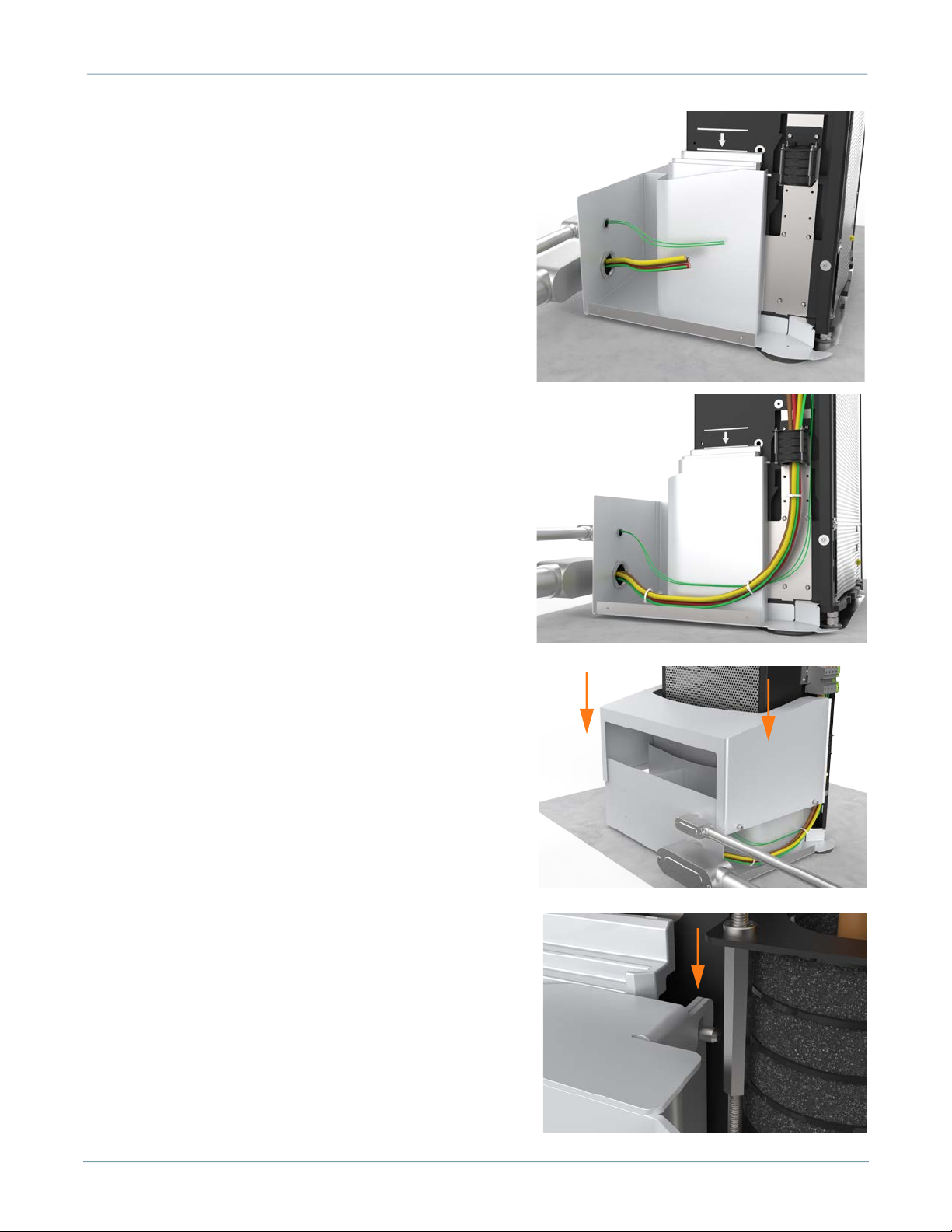
6. Position the SCE box base around the back of the station.
Be careful not to slide the bottom edge of the box base
underneath the surface mount plate.
Note: The box base cannot be installed on the station if the
lower rear cover panel is already installed.
7. Install the lower rear cover panel inside the gap between
the box base and the station:
a. Using two hands, one on each side of the lower rear
panel, align the guide tabs on the lower rear panel to the
matching slots on the Express 250.
b. Squeeze the sides of the panel inward to fit the tabs into
place in the C-channel, inside the watertight gasket.
Carefully push the panel down.
Note: The charging station has guide marks on the frame, to
show initial and final cover locations.
8. Use a T25 Torx to fasten the box base to the station with 4
screws on each side (8 total, included in the SCE Kit).
Torque to 4 Nm (35 in-lbs).
9. Install surface wireways between the service panel and the
Express 250 box base.
10. Fasten elbows to the Express 250 box base and to the
wireway using a code-approved sealing method.
ChargePoint Charging Stations
14
11. Pull all wiring through the wireways into the box base.
12. Go to the sections in the Express 250 Installation Guide
for wiring the AC conductors (and DC if pairing the
station). Land all applicable wires (AC, shunt trip, DC,
and Ethernet) per the installation instructions.
13. Slide the box cover over the box base.
14. Ensure the top corners of the box cover slide over the box
base guide pegs.

Express 250
15
15. By hand, tighten the two captive screws on each
bottom side edge that fasten the cover to the base.
Torque to 4 Nm (35.4 in-lbs).
16. Open the Power Module holders.
17. Install the right and left extrusions, aligning the
cutouts over the edges of the SCE box cover. SCE
extrusions have five captive screws each (one
bottom, two middle, two top). The bottom rear screw
is not present. Fasten these captive screws as
mentioned in the Installation Guide.
Note: For installation or servicing, SCE extrusions can be
removed without removing the SCE or rear bottom
panel. However, if the rear bottom panel must be
removed, first remove the SCE cover and loosen the box
base side screws.
Continue Normal Installation
1. Continue following the Express 250 Installation Guide to complete the rest of the station installation:
install Power Modules, the front EMI shield, and all other cover panels
2. When on-screen configuration prompts for either “replacement” or “new installation”, choose New.
3. Complete normal Express 250 pinpointing procedures through the end of the manual.

75-001417-01 r1
chargepoint.com/support
Warranty Information and Disclaimer
The Warranty you received with your Charging Station is subject to certain exceptions and exclusions. For example, your use of, or
modification to, the ChargePoint® Charging Station in a manner in which the ChargePoint® Charging Station is not intended to be used
or modified will void the limited warranty. You should review your warranty and become familiar with the terms thereof. Other than
any such limited warranty, the ChargePoint products are provided "AS IS," and ChargePoint, Inc. and its distributors expressly disclaim
all implied warranties, including any warranty of design, merchantability, fitness for a particular purposes and non-infringement, to the
maximum extent permitted by law.
Limitation of Liability
CHARGEPOINT IS NOT LIABLE FOR ANY DIRECT, INDIRECT, INCIDENTAL, SPECIAL, PUNITIVE OR CONSEQUENTIAL DAMAGES,
INCLUDING WITHOUT LIMITATION LOST PROFITS, LOST BUSINESS, LOST DATA, LOSS OF USE, OR COST OF COVER INCURRED BY
YOU ARISING OUT OF OR RELATED TO YOUR PURCHASE OR USE OF, OR INABILITY TO USE, THE CHARGING STATION, UNDER
ANY THEORY OF LIABILITY, WHETHER IN AN ACTION IN CONTRACT, STRICT LIABILITY, TORT (INCLUDING NEGLIGENCE) OR
OTHER LEGAL OR EQUITABLE THEORY, EVEN IF CHARGEPOINT KNEW OR SHOULD HAVE KNOWN OF THE POSSIBILITY OF SUCH
DAMAGES. IN ANY EVENT, THE CUMULATIVE LIABILITY OF CHARGEPOINT FOR ALL CLAIMS WHATSOEVER RELATED TO THE
CHARGING STATION WILL NOT EXCEED THE PRICE YOU PAID FOR THE CHARGING STATION. THE LIMITATIONS SET FORTH HEREIN
ARE INTENDED TO LIMIT THE LIABILITY OF CHARGEPOINT AND SHALL APPLY NOTWITHSTANDING ANY FAILURE OF ESSENTIAL
PURPOSE OF ANY LIMITED REMEDY.
FCC Compliance Statement
This equipment has been tested and found to comply with the limits for a Class A digital device pursuant to Part 15 of the FCC Rules.
These limits are designed to provide reasonable protection against harmful interference when the equipment is operated in a
commercial environment. This equipment generates, uses, and can radiate radio frequency energy and, if not installed and used in
accordance with the manufacturer’s instruction manual, may cause harmful interference with radio communications. Operation of this
equipment in a residential area is likely to cause harmful interference, in which case, you will be required to correct the interference at
your own expense.
Important: Changes or modifications to this product not authorized by ChargePoint, Inc., could affect the EMC compliance and revoke
your authority to operate this product.
Exposure to Radio Frequency Energy: The radiated power output of the 802.11 b/g/n radio and cellular modem (optional) in this
device is below the FCC radio frequency exposure limits for uncontrolled equipment. The antenna of this product, used under normal
conditions, is at least 20 cm away from the body of the user. This device must not be co-located or operated with any other antenna or
transmitter by the manufacturer, subject to the conditions of the FCC Grant.
FCC/IC Compliance Labels:
Visit chargepoint.com/labels/
Other manuals for Express 250
4
Table of contents


