Charles Machine Works Ditch Witch PR482 User manual

Original Instruction
PR482/SK5PR
Attachment Operator’s Manual
Publication number: ID0443833; page 1 of 6
Foreword
Read and understand this manual and the machine operator’s
manual before using your attachment. Keep it with the
equipment at all times for future reference. If you sell your
equipment, be sure to give this manual to the new owner.
If you need a replacement copy, contact your Ditch Witch®
dealer. Visit our website at www.ditchwitch.com or write to
the following address:
The Charles Machine Works, Inc.
Attn: Marketing Department
PO Box 66
Perry, OK 73077-0066
USA
The descriptions and specifications in this manual are subject
to change without notice. The Charles Machine Works, Inc.
reserves the right to improve equipment. Some product
improvements may have taken place after this manual was
published. For the latest information on Ditch Witch
equipment, see your Ditch Witch dealer.
PR482/SK5PR Attachment
Operator’s Manual
Issue number 2.0/OM-8/2021
Part number ID0443833
Copyright 2017, 2021
by The Charles Machine Works, Inc.
Ditch Witch is a registered trademark of
The Charles Machine Works, Inc.
Equipment Modification
This equipment was designed and built in accordance with applicable
standards and regulations. Modification of equipment could mean
that it will no longer meet regulations and may not function properly
or in accordance with the operating instructions. Modification of
equipment should only be made by competent personnel possessing
knowledge of applicable standards, regulations, equipment design
functionality/requirements and any required specialized testing.
Intended Use
The PR482/SK5PR attachment is designed for removing rocks
and small debris, and for thatching.
Safety Awareness
• Read and follow all safety precautions.
• Mark proposed path with white paint and have underground
utilities located before working. In the US or Canada, call 811 (US)
or 888-258-0808 (US and Canada). Also contact any local utilities
that do not participate in the One-Call service. In countries that do
not have a One-Call service, contact all local utility companies to
have underground utilities located.
• Mark jobsite clearly and keep bystanders away.
• Wear personal protective equipment. Do not wear jewelry or loose
clothing that can catch on controls.
• Use equipment carefully. Stop operation and investigate anything
that does not look or feel right.
• Contact your Ditch Witch dealer if you have any question about
operation, maintenance, or equipment use.
• Safety videos are available at www.ditchwitch.com and from
Ditch Witch dealers.
Safety Alert Classifications
These classifications and the icons work together to alert you to
situations which could be harmful to you, jobsite bystanders or your
equipment. When you see these words and icons in the book or on
the machine, carefully read and follow all instructions. YOUR SAFETY
IS AT STAKE.
indicates a hazardous situation that, if not avoided, will
result in death or serious injury. This signal word is to be limited to the
most extreme situations.
indicates a hazardous situation that, if not avoided,
could result in death or serious injury.
indicates a hazardous situation that, if not avoided,
could result in minor or moderate injury.
NOTICE indicates information considered important, but not hazard-
related (e.g., messages relating to property damage). IMPORTANT
can help you do a better job or make your job easier in some way.

Original Instruction
PR482/SK5PR
Attachment Operator’s Manual
Publication number: ID0443833; page 2 of 6
Safety Alerts Transport
Lift
Use a hoist capable of supporting the attachment’s size and
weight. See “Specifications” on page 5 or measure and weigh
attachment before lifting.
Controls
1Moving parts.
Contact can cause serious
injury. Stay away.
2Thrown objects.
Impact can cause injury.
Wear hard hat and safety
glasses.
3Rotating
shaft. Crushing will cause
death or serious injury. Stay
away.
4Lift location.
Attachment Function
To raise rake, raise lift (loader) arms.
To lower rake, lower lift (loader) arms.
To curl/tilt rake up, tilt mount plate up.
To curl/tilt rake down, tilt mount plate
down.
To rotate roller clockwise (when facing
motor), engage attachment drive (auxiliary)
in forward (F).
To rotate roller counterclockwise (when
facing motor), engage attachment drive
(auxiliary) in reverse (R).
00i 015
c00ic016c eps
c00ic018c eps
00i 017

Original Instruction
PR482/SK5PR
Attachment Operator’s Manual
Publication number: ID0443833; page 3 of 6
Connect Attachment
Attachment
1. Position attachment on
level surface with enough
space behind it to
accommodate machine.
2. Start engine.
3. Tilt mount plate (2)
forward.
4. Position mount plate in
the upper lip of the
receiver plate (1) on
attachment.
5. Raise lift arms while tilting back mount plate.
6. Pins will automatically
engage.
7. Ensure lock pins are
engaged by rotating
attachment down. Verify
that bottoms of lock pins
are visible under
attachment plate.
Hydraulic Hoses
1. Remove dirt and debris
from hydraulic couplers.
2. Connect male coupler on
attachment to female
coupler (3) on machine.
3. Connect female coupler
on attachment to male
coupler (1) on machine.
4. Ensure that connections are secure by pulling on hoses.
IMPORTANT: Before connecting attachment to machine,
ensure that mount and receiver plates are free of dirt and
debris and that latch handles are down.
IMPORTANT: Attachment should be raised enough to clear
the ground. Mount plate should be tilted back fully.
t05om026c.eps
12
t43om007w.eps
Pressurized fluid or air
could pierce skin and cause injury or
death. Stay away.
To help avoid injury:
• Use a piece of cardboard or wood, rather than hands, to
search for leaks.
• Wear protective clothing, including gloves and eye
protection.
• Before disconnecting a hydraulic line, turn engine off
and operate all controls to relieve pressure.
• Lower, block, or support any raised component with a
hoist.
• Cover connection with heavy cloth and loosen
connector nut slightly to relieve residual pressure. Catch
all fluid in a container.
• Before using system, check that all connections are tight
and all lines are undamaged.
• If you are injured, seek immediate medical attention
from a doctor familiar with this type of injury.
Hot parts may cause burns.
Do not touch until cool or wear gloves.
To help avoid injury: Wear gloves when connecting and
disconnecting hydraulic hoses and wait until machine has
cooled before touching hydraulic components.
2
1
3
t35om011w.eps
2
1
3

Original Instruction
PR482/SK5PR
Attachment Operator’s Manual
Publication number: ID0443833; page 4 of 6
Operate Attachment
1. Drive machine to starting point.
2. Stop forward movement.
3. Lower rake to the ground.
4. Start roller in the opposite direction of machine travel.
5. Increase engine speed to full throttle. If operating in heavy
rock, reduce speed slightly.
6. Operate at ground speed between 3 and 5mph under
normal conditions. In heavy rock, reduce the ground speed
to 1-3mph.
7. Move machine forward or backward as desired.
8. When raking is complete, stop machine movement.
9. Decrease engine speed to half throttle.
10. Raise rake.
11. Stop rotation.
12. Lower rake to ground surface.
13. Decrease engine speed to idle and stop engine.
Adjustment
Endplates
Endplates collect
material in front of the
roller while clean
material passes between
the roller and the barrier.
With endplates in the
working position (down,
as shown) and the roller
parallel with skid-steer,
material can be moved
along to fill in low spots.
To dig deeper, rotate
endplates up as shown.
Angle
1. Turn off engine.
2. Remove pins (shown)
and manually move
rake to desired
position.
3. Install pins to secure
rake.
Rotating shaft. Crushing will
cause death or serious injury. Stay away.
To help avoid injury:
• Use only with machine equipped with operator
presence system.
• Keep everyone at least 10ft (3m) away.

Original Instruction
PR482/SK5PR
Attachment Operator’s Manual
Publication number: ID0443833; page 5 of 6
Application Techniques
Break Compacted Soil
Roll attachment plate back until guide wheels are lifted and
only the toothed roller is in contact with the ground. The rake
can be straight or angled, but the endplates should be rotated
up.
Debris Removal
After soil has been loosened, tilt attachment forward until
guide wheels control depth of the roller. Rake can be angled
for windrowing or straight with both endplates installed to
catch debris. Increase travel speed for this technique.
Finish Grading
Tilt rake forward until teeth of roller just touch soil. In this
position, the rake will collect material from high areas and
leave it in low areas. Increase travel speed for this technique.
Spreading Fill and Topsoil
Position rake so it is tilted on gauge wheels. Install endplates
and set windrow angle as needed to control material
movement.
Change Grade
To modify grade during finish grading, angle the rake to collect
and windrow the maximum amount of material toward
targeted area.
Thatch Grass Area
Tilt attachment plate forward to support the rake on the front
gauge wheels. Raise roller so teeth just graze the surface.
Travel speed should be slow and careful.
Operating Tips
• Do not travel or turn with skid-steer lift (loader) arms and
attachment raised.
• Keep roller level with the ground. Keep power rake level
with the ground, front and back.
• Do not drop power rake to the ground with roller turning.
High speed jolts can damage motor.
Storage
Couple hydraulic hoses to prevent contamination.
Store attachment upright in a clean, dry place. Cover
attachment to keep it clean.
Maintenance
10-Hour
Check Hydraulic Hoses and Fittings
Check hydraulic hoses for leaks every 10 hours.
Check Hardware
Check all hardware every 10 hours. Tighten as required.
Specifications
Specifications are called out according to SAE recommended
procedures. Specifications are general and subject to change without
notice. If exact measurements are required, equipment should be
weighed and measured.
To help avoid injury: Unless otherwise noted, all
maintenance should be performed with the engine off.
Dimensions U.S. Metric
H Height 18.5in 470mm
L Length 44.5in 1.13m
W Width 58.5in 1.48m
Attachment mass 487b 220.9kg
Performance U.S. Metric
Offset distance 3in 76.2mm
Raking width 48in 1.2m
Roller angle, both directions 30° 30°
Solid tires 11 X 4.00-5

Original Instruction
PR482/SK5PR
Attachment Operator’s Manual
Publication number: ID0443833; page 6 of 6
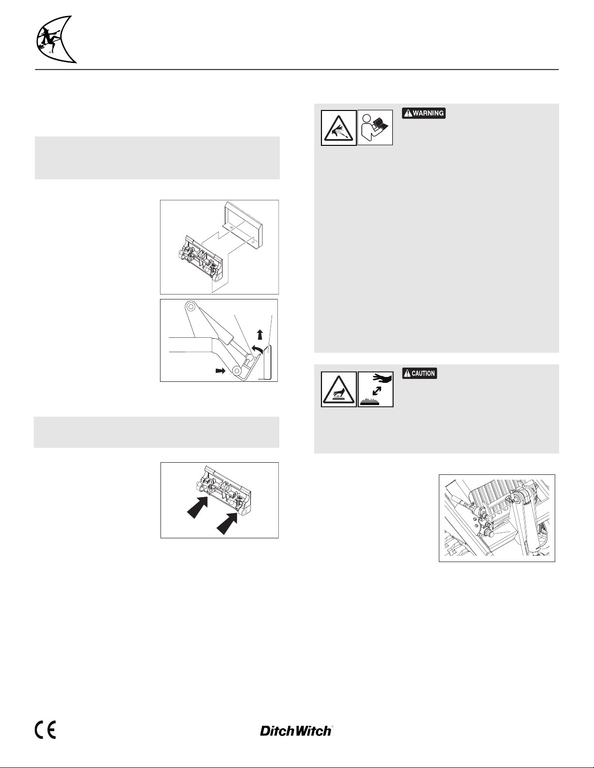
Support
Procedure
Notify your dealer immediately of any malfunction or failure of
Ditch Witch® equipment.
Always give model, serial number, and approximate date of your
equipment purchase. This information should be recorded and placed
on file by the owner at the time of purchase.
Return damaged parts to dealer for inspection and warranty
consideration if in warranty time frame.
Order genuine Ditch Witch replacement or repair parts from your
authorized Ditch Witch dealer. Use of another manufacturer's parts
may void warranty consideration.
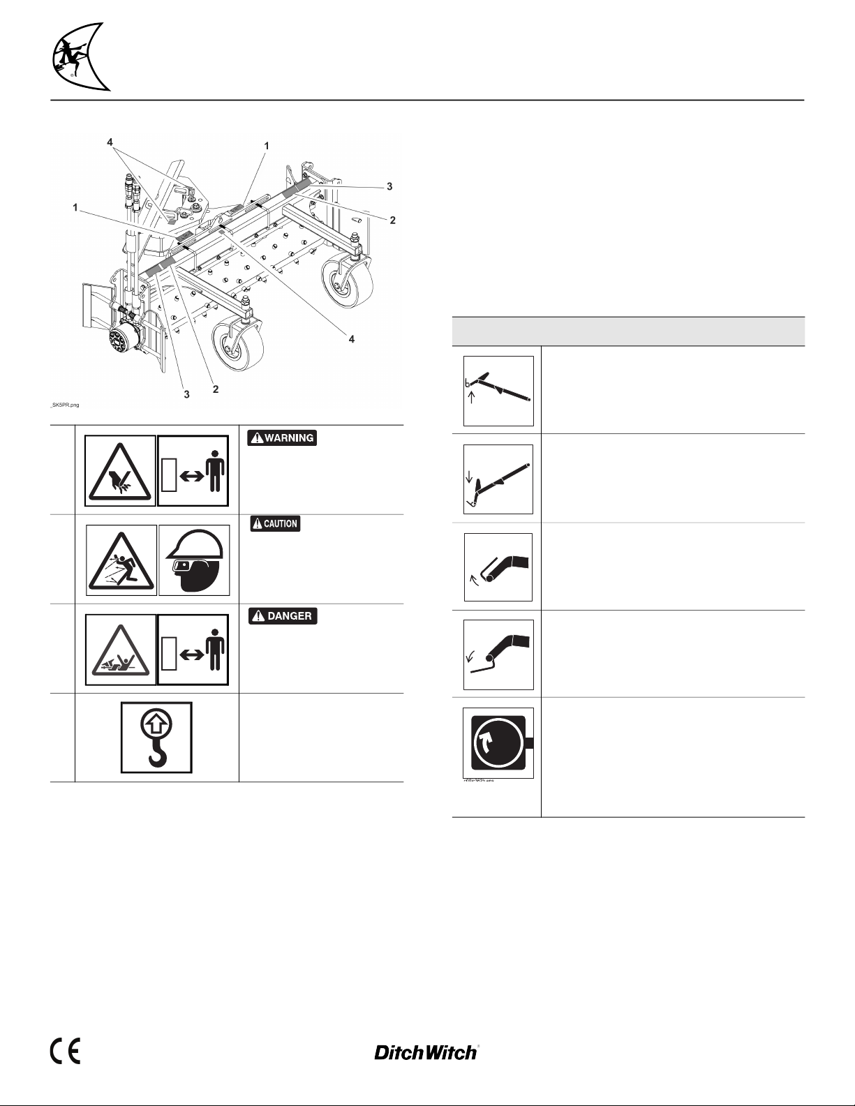
Serial Number Plate
1. Serial number
2. Attachment weight
3. Date of manufacture
Resources
Publications
Contact your Ditch Witch dealer for publications and videos covering
safety, operation, service, and repair of your equipment.
Ditch Witch Training
For information about on-site, individualized training, contact your
Ditch Witch dealer.
Warranty
Ditch Witch® Equipment and Replacement Parts
Limited Warranty Policy
Subject to the limitation and exclusions herein, free replacement parts will be
provided at any authorized Ditch Witch dealership for any Ditch Witch
equipment or parts manufactured by the Ditch Witch factory that fail due to a
defect in material or workmanship within one (1)year of first commercial use.
Free labor will be provided at any authorized Ditch Witch dealership for
installation of parts under this warranty during the first year following “initial
commercial” use of the serial-numbered Ditch Witch equipment on which it is
installed. The customer is responsible for transporting their equipment to an
authorized Ditch Witch dealership for all warranty work.
Exclusions from Product Warranty
• All incidental or consequential damages.
• All defects, damages, or injuries caused by misuse (including, but not
limited to, rollover), abuse, improper installation, alteration, neglect, or
uses other than those for which products were intended.
• All defects, damages, or injuries caused by improper training, operation, or
servicing of products in a manner inconsistent with manufacturer’s
recommendations.
• All engines and engine accessories (these are covered by original
manufacturer’s warranty).
• Tires, belts, and other parts which may be subject to another
manufacturer’s warranty (such warranty will be available to purchaser).
• ALL IMPLIED WARRANTIES NOT EXPRESSLY STATED HEREIN, INCLUDING
ANY WARRANTY OF FITNESS FOR A PARTICULAR PURPOSE AND
MERCHANTABILITY.
IF THE PRODUCTS ARE PURCHASED FOR COMMERCIAL PURPOSES, AS DEFINED
BY THE UNIFORM COMMERCIAL CODE, THEN THERE ARE NO WARRANTIES
WHICH EXTEND BEYOND THE FACE HEREOF AND THERE ARE NO IMPLIED
WARRANTIES OF ANY KIND WHICH EXTEND TO A COMMERCIAL BUYER. ALL
OTHER PROVISIONS OF THIS LIMITED WARRANTY APPLY INCLUDING THE
DUTIES IMPOSED.
Ditch Witch products have been tested to deliver acceptable performance in
most conditions. This does not imply they will deliver acceptable performance
in all conditions. Therefore, to assure suitability, products should be operated
under anticipated working conditions prior to purchase.
Defects will be determined by an inspection within thirty (30) days of the date
of failure of the product or part by Ditch Witch Product Support (DWPS) or its
authorized dealer. DWPS will provide the location of its inspection facilities or
its nearest authorized dealer upon inquiry. DWPS reserves the right to supply
remanufactured replacements parts under this warranty as it deems
appropriate.
Extended warranties are available upon request from your local Ditch Witch
dealer or the Ditch Witch factory.
Some states do not allow exclusion or limitation of incidental or consequential
damages, so above limitation of exclusion may not apply. Further, some states
do not allow exclusion of or limitation of how long an implied warranty lasts,
so the above limitation may not apply. This limited warranty gives product
owner specific legal rights and the product owner may also have other rights
which vary from state to state.
For information regarding this limited warranty, contact the DWPS
department, P.O. Box 66, Perry, OK 73077-0066, or contact your local dealer.
First version: 1/91; Latest version: 7/19
This manual suits for next models
1
Table of contents
Other Charles Machine Works Utility Vehicle manuals