Charles CMPH-75 SERIES User manual

Equipment Issue 1
First Printing, May 2009
Section CMPH-75CC-801
−CMPHtCROSS-CONNECT SERIES INSTALLATION GUIDE −
ECopyright 2009 Charles Industries, Inc. All rights reserved. Printed in the United States of America. Charlesris a registered trademark of and CMPHtis a trademark of Charles Industries, Ltd. Availability of features and technical specifications herein subject to change without notice. Page 1 of 3
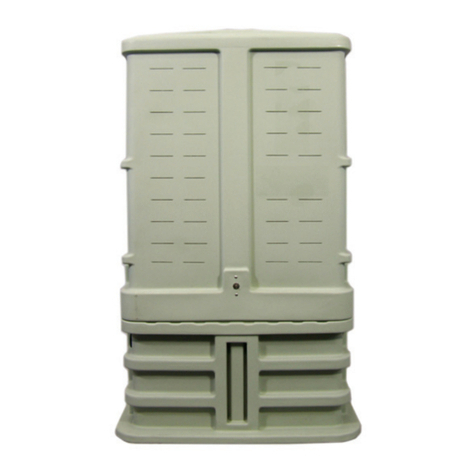
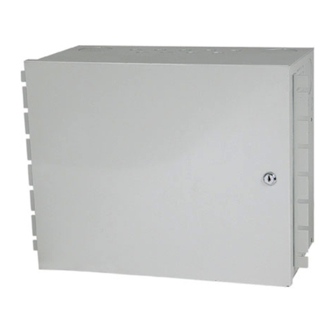
Figure 1. Typical CMPH Enclosure, Dome On and Dome Off Views
Flap Latch
secured via cup-washer
screw (see Steps 5 and 6)
Ground
Line Indicator
Label
or
Decal
Areas
Dome On Dome
Removed
Cross
Connect
Panel
(one on
both
sides)
- Installation Instructions -
CMPH-75XX Cross-Connect Series of
Charles Multi-Purpose Housing (CMPHt) Enclosures
1. GENERAL
1.1 Document Purpose
This document provides installation instructions for the CMPH-75XX
Cross-Connect Series of Charles Multi-Purpose Housing (CMPHt) enclo-
sures, which provide a quick and easy way to cross-connect up to 1200 feed
and distribution wire pairs using high-density terminal blocks in a single,
above-ground enclosure. See Figure 1 for a typical CMPH-75XX Cross-
Connect series model, see Table 6 for ordering information on all products in
this series, and call Charles Industries (see Part 3) to request more information.
- NOTE -
Hereafter the Charles Multi-Purpose Housing will be referred to as the
CMPH" or enclosure."
1.2 Document Status
Whenever this document is updated, the reason will be stated in this para-
graph.
1.3 Product Purpose and Description
The CMPH-75XX Cross Connect Series is designed to provide quick, flex-
ible, high-density, cross connections between feeder and distribution cables.
The enclosure’s internal framework and large swing-out panels hold up to 24,
50-pair, cross-connect terminal blocks. These pre-stubbed terminal blocks,
which contain factory-wired 25-pair or 50-pair wire-bundles that are termi-
nated with 710 or MS@connectors, can be installed initially, or easily added
at a later date without disruption of existing circuits. The swing-out panels
facilitate cable storage in the base prior to cable splicing and installer connec-
tions. This center-fed, cross-connect, interface system accommodates from
300 to 1200 pairs.
1.4 Exterior components. The CMPH enclosure offers easy installation, su-
perior structural strength, 360_technician access, and generous internal
connection capacity. The green light-weight base and dome are made of a dura-
ble material which minimizes condensation and protects against corrosion,
floods, fire, weather, dirt, insects, intrusion, dents and impact. The top piece
of the CMPH is the dome, designed to overlap the base for a flood-protective
bell-jar effect. The base has an open top, corrugated ribbed walls, internal,
dual-purpose, molded-in, channel grooves (which accept most metallic stakes
as well as the vertical channels of the internal framework, see Figure 2), and
an open bottom. Easy replacement installations and easy underground cable
access is provided via this open base bottom.
1.5 Interior components. At the center of the cross-connect CMPH is an in-
ternal metallic framework that supports two, large, hinged, heavy-duty,
wind-latchable, side panels, both of which are factory-equipped with either
25-pair or 50-pair terminal blocks (see Table 6 for the specific type of terminal
block used). Up to 24 50-pair terminal blocks can be equipped in a single high-
density CMPH. Factory-prewired at the back of each terminal block is a
5-foot-long wire-bundle stub that is terminated with either a 710 connector or
an MS@splice connector (per the specific model ordered). New or existing pre-
connectorized feed and distribution cables (wire gauge size of 22-26 AWG),
which also are terminated with either 710 or MS@connectors, enter the bottom
of the CMPH from a trench or vault and are mated with the connectors at the
end of the terminal blocks’ wire-bundle stubs. After the cable connections are
made inside the CMPH base (lower connections), the installer performs all
wire jumper connections (upper connections). Wire race-ways are provided
for protection of all cable and jumper pairs as they are installed. The hinged,
side-access style, terminal block panels enable the installer to create very
short, easily traceable, jumper runs. The installer routes and connects jumpers
between the proper toggle of the correct terminal block in one door panel (feed-
er side) and the proper toggle of the correct terminal block in the other door
panel (distribution side).
For models equipped with MS@splice connectors, the MS@connector has a
two part block which contains U-contacts, wire channels, and cut-off blades.
The body of the MS@splice cover module assembly and base are crimped to-
gether to terminate Feeder or Distribution pairs. Binder groups may be
identified on the module mouth and pairs can be identified on tagging cable
labels.
Also included with each CMPH is a test kit, a jumper wire spool holder, pair
identification labels, wire race-ways, splice bars, a ground bar, and other ac-
cessories (see Table 6).
1.6 Product Mounting Type and Location
The CMPH is an above-grade enclosure, the base of which is typically
installed in a trench or hole in the ground up to the base’s ground line indica-
tor, either in new or rehab-type installations around existing cables. The base
also can be mounted directly to a concrete pad using a special bracket, as well
as stake mounted. Molded channel grooves, located at the center of each inte-
rior side wall, enable stake mounting using 30”, 36” or 42” stakes. These
grooves accept most new and existing enclosures’ mounting stakes. The
ribbed or corrugated base walls provide excellent stability in most soil types.
The dome mounts on the base and protects all equipment installed or mounted
inside the CMPH.
1.7 Features
DSide-access terminal blocks on swing-out panels facilitate cable storage
before splicing and provide greater room for spliced connections
DWeather-resistant, gel-filled, Tyco Dat@ Term terminal blocks provide
application flexibility, rapid, pair-at-a-time, toolless, no-strip wire con-
nections
D50-pair terminal blocks equipped with 5’ stubs which are terminated
with 3M MS@splice terminals
DPlastic base provides ease of cabinet installation over existing cables
and facilitates cabinet rehabilitation
DSingle cabinet mounting footprint for 300-1200 wire pairs
DDurable, light-weight, plastic, impact-resistant material provides long
life
DBase with overlapping dome provides flood proof “bell jar” effect, to
minimize condensation and provide outstanding weather protection
DDesigned to meet Telcordia specification GR-3115-CORE
2. INSTALLATION
See Table 1 to perform a new CMPH enclosure installation. Table 2 describes
a new CMPH installation with stakes, and Table 3 describes an installation to
replace an existing enclosure (rehabilitation installation). Table 4 describes
how to make installer connections to the terminal blocks on the hinged interior
panels.
- CABLE DAMAGE WARNINGS -
Be careful not to damage any buried cables or service wires while digging either
to expose cables or to prepare a hole or trench, or while driving stakes.
- NOTE -
Never grasp or use the flap-latches as handles to lift the dome off the base; latch
breakage and possible enclosure intrusion could result.
Ground
Plate
Figure 2. Typical CMPH Enclosure, Dome Removed, Panels Open
Dome
Cup-washer screw
(attached to base via
lanyard, see Step 7)
Hasp
(see Step 23)
Base
collar
Base
Inside
frame-
work
Locking Pins
Feeder Side Hinged panel
Distribution Side
Hinged panel
Up to 12, 50-pair,
terminal blocks
can be installed
on each door
- GROUNDING WARNINGS -
Always follow local codes and company practices for performing proper cable
and site bonding and grounding, and perform all bonding and grounding prior
to other electrical and communications connections.
Table 1. Installing a New CMPH Enclosure
Step # Instruction
1. hObtain tools, materials and equipment. Gather the following
equipment to perform the CMPH installation.
h216 tool or can wrench hTrenching and digging equipment and tools
hCharles CMPH model hCable grounding materials and tools
hScissors, knife or snips hCable opening and management equipment
hLevel hClean, dry, pea gravel (3/8"-5/8" diameter)
hMeasuring tape hConduit and conduit caps (optional)
hSoil tamping tool(s) hWrenches or socket set
hSoil for backfill hInsulated work gloves (optional, to handle metallic stakes)
hSite cleanup tools
2. hPrepare trench. Do not damage any buried cables or wires while
digging. Dig and prepare the cable trench, per company practice.
3. hPlace cables (or conduit or innerduct) in trench. Follow company
practice to lay, place, and cut any cables and innerduct or conduit.
4. hUnpack and inspect equipment. Without damaging the CMPH
exterior, remove the CMPH from its packaging. Inspect the unit upon
delivery; if damaged in transit, report the damage to the shipping
company.
5. hUnlock the CMPH. Unlock
the CMPH using a 216 tool or
can wrench at the two cup-
washer screws (one at each
side of the CMPH); turn the
cup-washer screws counter-
clockwise until they freely
hang from their lanyard.
When locked, the cup-washer
screws prevent movement
of the flap-latches.
Flap Latch
Cup-washer
screw
216 Tool
Lanyard
6. hDisengage the flap-latches. Each limited-flexibility
flap-latch contains a hole in it which accepts the
round standoff protruding from the side of the base
collar. Each latch must be pulled out or away from
base side wall just enough to clear the length
of the protruding standoff. Maintain the
flexed or pulled-out latch position by
temporarily inserting the cup-washer
screw or an item of similar diameter or
thickness under each latch (between
the latch and the side wall). Do not
pry or flex the latches too far, only
enough to clear the standoff. Never
grasp or use the flap-latches as
handles to lift the dome off the base; latch
breakage and possible enclosure intrusion
could result.
Standoff
Cup-washer screw
Latch
Pull latch out. Insert
cup-washer screw
under latch.
7. hRemove the dome.
While the flap-latches
are properly disen-
gaged from the base
standoffs, grasp the
ribs at each side of
the dome and lift up
to remove the dome
from the base. The
cup-washer screws
remain attached to the
base via the lanyard (or
chain). Set aside the
dome for later use.
Standoff on Base
Cup-washer screw affixed via lanyard
Pull up on
ribs

030-300377 Rev. A Section CMPH-75CC-801
−CMPHtCROSS-CONNECT SERIES INSTALLATION GUIDE −
2
0905I1P1
8. hFind and remove red plastic bag. Remove the red bag labelled
“moisture barrier” hanging on one of the frame’s splice bars or
brackets. Set it aside for later use.
9. hOptional - Replacement or rehabilitation mountings only. For
applications to replace old enclosures, continue with the steps in
Table 3.
10. hDetermine and mark base installation location. To d etermi n e
exactly where to place the base in the trench, use the base itself as a
positioning template by placing it up over the top of the conduit,
innerduct, or cables (route the cables through the base) and lowering
the base to the ground. Analyze the site and position the base at its
proposed final orientation and horizontal positioning in the trench or
hole and adjust accordingly. Mark this proposed final spot by remov-
ing a shallow layer of top soil from around the outside perimeter of
the base about 2-4 inches wider than the base. Remove the base
and set it aside.
11. hDig a hole for the base. Caution: Avoid damaging buried cables,
wires, inner- duct, conduit or ground equipment whenever
digging. At and within the marked perimeter boundary, dig straight
down to a depth of 9 inches. Do not dig too deep.
12. hOptional - Stake mountings only. For stake mounting applications,
continue with the steps in Table 2.
13. hPut base in hole or trench and route cable(s) through base.
Route the cables and conduit or innerduct up through the bottom of
the base, then put the base in the prepared hole or trench.
14. hVerify proper base depth. Before backfilling, verify the base is at the
proper depth, approximately 9 inches deep. Rest the base on solid or
well-tamped soil when measuring this distance. Verify the base
ground line indicator is at the same level as the final-grade ground
line. Remove, add, or tamp more soil as necessary.
15. hLevel the base. Verify the level (or plumb) of the base. Check the
level at either the top surface of the base, or against one of the inter-
ior vertical channels of the metal frame. Check the level in both
dimensions; front to back, and side to side. Make any needed
base-bottom soil adjustments to get a good or true level or plumb
line.
16. hPrepare earth ground. Always follow local codes and company
practice when preparing earth ground and when grounding cables or
equipment. If an earth ground is not present at the CMPH site and
local code or practice requires an earth ground, prepare one now.
Attach the earth ground to the CMPH’s ground lug on the ground
plate (Step 3) using a ground wire of proper gauge, per company
practice.
17. h
Backfill soil inside
the base and tamp.
First plug, cap, or
cover all channel,
conduit, or innerduct
openings. Then per
company practice,
backfill soil inside the
base, tamping soil
periodically, to the
ground line mark.
This adds stability
and prevents any
company-approved
gravel (Step 19) from
falling or slipping
under the base sides
when it is added.
3-5 inches of
gravel inside
the base
(Step 19)
Base
Top
ÏÏÏÏÏÏÏÏÏÏ
ÏÏÏÏÏÏÏÏÏÏ
ÏÏÏÏÏÏÏÏÏÏ
ÏÏÏÏÏÏÏÏÏÏ
ÏÏÏÏÏÏÏÏÏÏ
ÏÏÏÏÏÏÏÏÏÏ
ÎÎÎÎÎÎÎÎ
ÎÎÎÎÎÎÎÎ
ÎÎÎÎÎÎÎÎ
ËËËËËËËË
Soil
Pea Gravel
Soil
Backfill and tamp outside the base. With the base in place, backfill
the trench or hole outside of the base. While backfilling, tamp the soil
or fill and check the base level once or twice. Continue to add and
tamp the soil until the soil is at the base ground-line mark.
8"
9"
Side View
Moisture
Barrier (see
Step 18)
Base
Bottom
Ground
Line
18. hPlace the red-plastic bag or sheet. Retrieve the provided, red-plas-
tic, vapor-barrier bag previously set aside, cut it open on all but one
long edge to make one large plastic sheet, verify it does not have any
large holes in it (if it does, seal them with duct tape), and place it into
the base on top of the soil fill. Completely cover the soil. Fit the bag
around and encircle the cables, conduit, or innerduct, spread it
outward from the center, and press all sheet edges downward where
they make contact with the base walls. Alternately, cut a hole or “X” in
the center of the sheet, drop the sheet down over the centered
cables or conduit group, bring it all the way down to the tamped soil
or fill, fit the sheet’s inner hole edges snugly around the cables or
conduit, and spread it out as underlined above. When installed
properly, this sheet acts as a vapor barrier and aids moisture run-off
into the soil. Failure to use the plastic moisture-barrier bag on
top of the soil significantly increases the risk of condensation
inside the enclosure.
19. hAdd gravel inside the base. Pour 3-5 vertical inches of
company-approved gravel (gravel minimizes condensation and drains
well) into the base (about to the top base rib, or 1” below any
innerduct or conduit opening) on top of the soil. Use 5/8” (or less)
diameter pea gravel, or clean, dry, non-porous, gravel rock only (cut
stone retains more moisture). Five 18-pound bags work well. Spread
out and level the gravel.
20. hEnd of base installation - determine next procedure. If cable and
wire connections will now be performed, follow the steps in Table 4
and also follow local practices and equipment manufacturer
instructions for the proper procedures. If further cable work will NOT
be performed at this time, close the CMPH enclosure as described in
the following steps.
21. hInstall dome. Locate the
dome and lift it up and over the
interior framework and
equipment. Lower the dome
until it overlaps and
self-latches to the base. Verify
the standoffs protrude through
the holes in the latches
(self-latch feature).
Dome slot
self-aligns
with standoff
on base
Latch
shown
detached
for visual
clarity only.
Base
collar
22. hLock the CMPH. Lock the
CMPH by re-inserting and
turning the cup-washer
screws clockwise into the
threaded holes provided for
them in the standoffs.
Tighten the cup-washer
screws with a 216 tool or
can wrench.
Flap Latch
Cup-washer
screw
216 Tool
Lanyard
23. h(Optional) Padlock
the CMPH. For
models equipped
with an optional
hasp, the CMPH
also can be locked
by inserting a
padlock through the
holes in the hasp
provided at the front
of the enclosure.
Hasp for padlock
(orderable option)
24. hEnd of CMPH placement. Clean up site. If no more equipment or
cable work will be performed at this time, clean up the site, fill and
tamp any trenches, replace any removed sod, restore the landscape
to it’s original condition, pick up all equipment, and optionally leave
this document inside the CMPH for future reference.
Table 2. Installing the CMPH with New Charles Stakes
Step # Instructions
Charles offers some CMPH models which include two mounting stakes (either 30", 36", or 42"
long). All stakes have identical hole patterns. This table describes how to install these models.
1. hPrepare the CMPH, trench, and cable. Perform Steps 1-11 of
Table 1 to open the enclosure and prepare the hole or trench and the
cables or conduit. Verify the base installation site is ready and
suitable for metallic stakes.
2. hRemove stakes from CMPH
framework. Two mounting
stakes are packed with the
CMPH and attached to
the frame with cable ties.
Detach the stakes from the
frame and remove the
packing used for shipping
purposes.
Cut the cable ties
which secure the
stakes to the frame
3. hDetermine which grooves to use for stakes. The base contains a
molded-in dual-purpose groove at the center of each wall to accept
the U-shaped mounting stakes (as well as the U-shaped vertical
channels of the frame). Per local company practice and site
conditions, select two wall grooves that are appropriate for stake
attachment purposes (the grooves on the narrow walls are typically
used).
Base Bottom View
Open
Inside
Area
Alternate Mounting
Grooves (generally used
in vault applications)
25.5"
29.5"
2"
1.5"
2"
17"
Base Top View
Preferred U-shaped channel
grooves for mounting stakes
4. h
1.6"
1.1"
Top View
of Stake
Set stake
into groove
Attach stakes to grooves in base. Set the base on the ground or a
raised surface to access the grooves through the base bottom. On
the inside of the base, remove the nuts and washers from the bolts
(which are 4” apart) that secure the frame channels in place. On the
mounting stake, the distance between the first and third hole down
from the top of the stake is 4”. Insert the top of the stake into the
base, rotate the stake so it will fit properly into the base groove (so
the perimeter contours match), align the stake holes with the bolts in
the base, and set the stake in place in the groove. Attach the lock
washers and nuts that were removed to secure both the mounting
stake and frame channel in place. Repeat for the other stake.
Base Side View
4"
1"
1.3"
Bolt for frame channel
and stakes
4"
Charles
Stake
Top View of Base
Wall at Groove
1.125"
3"
1"
1"
1.2"
Carriage
Bolt
3"
5. hVerify hole or trench accommodates stake length. Lift the base
and attempt to place it back in place in the trench or hole. If the
trench is deep enough to accommodate the length of stake
protruding from the bottom of the base, skip the rest of this step. If
the hole or trench is not deep enough to accept the stakes, and the
weight of the base is not enough to drive the stakes the length
needed to allow the base to rest at its proper depth, then once again
use the base as a template to mark the exact stake locations in the
ground where more soil must be removed. Remove the base from
the hole, and at the stake-hole indentations, dig down just enough to
accommodate the length of the stake.
6. hSet base in place, bring cables into base. When the hole is deep
enough for the stakes, again lift the base by its walls or ribs and set
it back into the hole, being sure to enclose or encompass within the
base all cables, innerduct, conduit or equipment present at the site
and intended for storage inside the enclosure.
7. hFinish the installation. Perform Steps 14 through 24 in Table 1 to
finish the installation. Be sure to backfill and firmly tamp soil into the
stake holes when backfilling.
Table 3. Installing Replacement or Rehabilitation Enclosures
Step # Instructions
The Charles CMPH has the same footprint as the UPC 1200 series. These instructions describe
how to replace a UPC 1200 with a Charles CMPH. To replace enclosures with smaller footprints,
remove the smaller enclosure and dig a wider hole, as described in Step 10 of Table 1.
1. hPrepare the base, trench, and cables. Locate the old or existing
enclosure (such as the UPC 1200 series) to be replaced. Perform
Steps 1-8 of Table 1 to prepare the new Charles CMPH enclosure,
the hole or trench, and the cables or conduit (skip Steps 2-3 if
trenching and new cable placement is not required).
2. hDig around existing enclosure. Remove the dirt from around the
existing enclosure. Dig deep enough to allow the enclosure to be
lifted and removed.
3. hPrepare existing enclosure for removal. Remove the bottom
panels of the UPC 1200. Locate the mounting stakes and remove
the nuts and bolts from them. Remove all attachments to the
enclosure, including cable supports and tie wraps, bonding
connections, and grounding connections.
4. hRemove the old enclosure. Completely remove the existing
enclosure.
5. hProtect cables and connections. Per company practice, wrap the
existing splice as tightly as possible without damaging the
connections.
6. hAnalyze condition of existing mounting stakes. Inspect the
existing mounting stakes for possible re-use. If they are
deteriorated, bent, out of alignment, or have a hole pattern that will
not work with the Charles CMPH base, carefully remove the stakes
and install new ones per company practice (consult Table 2 if
desired).
7. hOptional - remove the CMPH’s horizontal splice bars and/or
ground bracket. Analyze whether or not it will be necessary to
temporarily remove any of the CMPH’s internal, horizontal,
supportive splice bars or brackets in order to fit the existing cabling,
connections, splices, and equipment into the CMPH during the base
installation. After base installation, re-attach the bars and brackets
(Step 10).

030-300377 Rev. A Section CMPH-75CC-801
−CMPHtCROSS-CONNECT SERIES INSTALLATION GUIDE −
3
0905I1P1
8. hSet base in place. Lift the base over the existing cabling and
equipment, and route the wrapped splice and all equipment up
through the base bottom while lowering the base to the bottom of the
hole. If the existing stakes were used, verify they are inside the
base. If new stakes were attached to the base, insure the hole
accommodates them. Perform Steps 14-15 of Table 1 for the proper
base depth and level.
9. hAttach base to re-used stakes. Remove the nuts and washers
from the 4 bolts located inside the CMPH base that secure the frame
channels in place (2 bolts on each side, 4” apart). Manipulate the
base and/or stake tops so the re-used stakes fit into the preformed
stake grooves in the base walls. Align the base bolts with the stake
holes, and re-attach the washers and nuts onto the bolts. Firmly
tighten nuts.
10. hAttach cables to bars and brackets. If the splice bars or brackets
were removed, re-install them now in the best positions to support
(and ground) the equipment. Per company practice, attach or mount
all cables and equipment to the internal framework (bars, brackets)
of the CMPH. Re-attach any grounding, bonding, and cable
connections previously unattached to remove the old enclosure.
11. hClose the CMPH, clean the site. Perform Steps 19-24 in Table 1 to
close the CMPH and restore the site to its previous condition.
Table 4. Making Ground, Cable, and Jumper Connections
Step # Instructions
1. hRoute cables into CMPH enclosure. Per company practice and
local codes, bring the feed and distribution cables into the CMPH
enclosure through the open base bottom. Secure and stabilize the
cables per company practice.
2. hOpen cables. Per company practice, perform all cable opening
procedures.
3. hBond and strain-relief the
cables. Ground or bond the
cable(s) to the ground posts
provided on the ground plate.
Perform cable strain relief and
bonding per company practice. Attach earth ground to ground lug
Attach cable bond
straps to posts
Ground Plate
Posts to attach plate to ground bracket
4. hSplice cables to terminal block stubs. Per company practice,
perform cable splicing and connection procedures to connect the
feeder and distribution cables to the appropriate terminal block
wire-bundle stubs inside the CMPH enclosure. Perform cable
management techniques per company practice.
5. hPerform labelling. Fill out and complete the label provided on the
top of the internal CMPH framework to facilitate pair identification.
Each toggle port of each terminal block is labelled by the terminal
block manufacturer.
6. hMount jumper wire spool. Mount the field-provided jumper wire
spool on the provided jumper wire spool holder located inside the
enclosure.
7. hLocate proper toggles for
first wire pair. Locate or
identify the correct toggle in
the correct feeder terminal
block for the first wire pair
to be placed in service.
Also locate the correct
toggle in the correct
distribution block.
8. hPull jumper wire from spool. Pull the jumper wire from the spool
toward the identified first toggle in the feeder terminal block.
9. hPrepare wires of first wire pair. Straighten the last 1−2’’ of the
conductor pair wires to be installed and placed in service. Trim the
conductor wire ends evenly, but do not strip the insulation.
10. hOpen feeder terminal block toggle and insert
wires into toggle ports. Pinch and pull back the
toggle. Insert the pair into the ports, one wire per
port (two port holes per toggle). Note that ports are
labeled “T” for tip and “R” for ring. Wires should be
inserted about 3/8’’ before bottoming out.
11. hClose toggle. While holding the conductor wires in the toggle ports
with one hand, with the other hand push the toggle closed until it locks
shut. Tug gently on each individual wire to verify a good connection
was made. If a good connection was not made (wire is loose),
disconnect and remove the pair by pinching and pulling back the
toggle, remove the wire pair, then repeat Steps 9 and 10 until a good
connection is made. Note: Trim away the scored insulation area of
wire prior to reconnection.)
12. hRoute and dress jumper wire toward distribution block. Unwind
enough jumper wire from the spool to reach the identified toggle in
the distribution terminal block. Dress the jumper wire down toward
the bottom of the toggle, then route it sideways along the bottom of
the row of toggles toward the side of the block. Route the jumper
down the block, then over to the side, toward the hinge side of the
door panel, then on towards the panel on the opposite side. Slip the
jumper wire through any installed cable management rings and
behind the race-ways and run guides provided in the CMPH. Do not
run wires across the front face of the terminal blocks.
13. hCut jumper wire to proper length. Per company practice, extend
the wire toward the targeted distribution block’s correct toggle, allow
ample wire slack, and then cut the jumper wire to the proper length.
14. hConnect wire pair to correct toggle of distribution terminal
block. Repeat Steps 9-11 for the proper toggle of the targeted
distribution terminal block.
15. hTest connection. To test the wire pair connections, insert the
provided Dat@Term terminal block test clip into the toggle locations.
Make sure the test clip alignment guide is on the hinge side of the
toggle. Attach test set to test clip and test per company practice.
16. hComplete the label. Per company practice, fill out the provided label
to identify the line placed in service.
17. hRepeat for all lines. Repeat above steps for all lines to be placed in
service.
18. hReplacing toggles. In the unlikely event a toggle is damaged,
toggle removal and replacement is accomplished as described
herein. Tyco Dat@ Terminals have rotating wire terminating toggles
that can be removed and replaced if needed. To replace a damaged
toggle: 1. Open damaged toggle to normal open position. 2. Push
toggle out of it’s block cell by rotating it past it’s normal open
position. This will cause it to break free of the holding mechanism in
the block without damaging the block. 3. Once free, remove toggle
from block and discard. 4. Insert new toggle. 5. Rotate toggle into
cell, using care to make sure the toggle axle is mated with the
bearing surface in the block. 6. Rotate toggle until it closes and the
toggle latch locks. Toggle is now replaced. 7. Close any
corresponding opened toggles.
19. hPerform cable management. Verify all equipment and cabling is
organized and will not contact the interior walls of the dome when
installed (keep items at least 1” from the vertical plane of the base
collar). This assures safe and smooth dome placement.
Table 5. Physical Specifications
Feature U.S. Metric
Height, overall 47 in. 119.4 cm
Height, base only, incl. collar 17 in. 43.2 cm
Height, dome only 33 in. 83.8 cm
Height, internal framework 30 in. 76.2 cm
Height, base bottom to ground line 9 in. 22.9
Depth, base (at wider footprint) 17 in. 43.2 cm
Depth, dome 14.5 in. 36.8 cm
Width, base (at wider footprint) 29.5 in. 75 cm
Width, dome 27 in. 68.6 cm
Weight, dome 21 lbs. 9.5 Kg
Weight, base 22 lbs. 10 Kg
Weight, base w/brackets and
terminal blocks
100 lbs. 45 Kg
Weight, two 30” stakes 5 lbs. 2.2 Kg
Weight, two 36” stakes 6 lbs. 2.7 Kg
Weight, two 42” stakes 7 lbs. 3.2 Kg
NOTE: All dimensions and weights are approximate.
Table 6. Model Number Ordering Information and Options
Model # Description
CMPH-7512CC-EMT 1200 Pair Cross Connect CMPH With Tyco Blocks
CMPH-7509CC-EMT 900 Pair Cross Connect CMPH With Tyco Blocks
CMPH-7506CC-EMT 600 Pair Cross Connect CMPH With Tyco Blocks
CMPH-7503CC-EMT 300 Pair Cross Connect CMPH With Tyco Blocks
Optional Equipment for Use with CMPH Cross Connect
CMPH-BOND10 Package of 10 ground plates, each plate
contains a ground lug and 6 bond posts.
Attaches to internal, horizontal, ground
bracket.
19-300545-0 100 pair Tyco Data Term
Terminal Block, 5 ft. cable,
3M MS2 connectors
UMS30-STD Universal Mounting Stake - 30 inches
UMS36-STD Universal Mounting Stake - 36 inches
UMS42-STD Universal Mounting Stake - 42 inches
Various replacement and optional parts are available, including bracket kits for vault-mounting. Contact Charles Industries for
more information.
3. CUSTOMER TECHNICAL SERVICE
If technical assistance or customer service is required, contact Charles Indus-
tries by calling or using one of the following options:
847-806-8500 (Technical Service local)
847-806-6300 (Customer Service)
800-607-8500 (Technical Service toll-free)
847-806-6653 (Customer Service FAX)
847-806-8556 (Technical Service FAX)
[email protected] (email)
www.charlesindustries.com (website)
Other Charles Enclosure manuals
