Charles CMPH User manual
Equipment Issue 2
Fourth Printing, March 2016
Section LTCMPH-75-802
ECopyright 2012−2016 Charles Industries, Inc. All rights reserved. Printed in the United States of America.
Charlesris a registered trademark of and CMPHtis a trademark of Charles Industries, Ltd. Availability of features and technical specifications herein subject to change without notice. Page 1 of 5
0316P4
Charles Multi-Purpose Housing (CMPHt)Enclosure
Installation Instructions
1. GENERAL
1.1 Document Purpose
This document provides installation instructions for the Charles Multi-Pur-
pose Housing (CMPHt) enclosure, which provides a quick and easy way to
attach, mount, and protect various types and quantities of copper and fiber
cables, splices, cases, and equipment in a protective, outside plant (OSP),
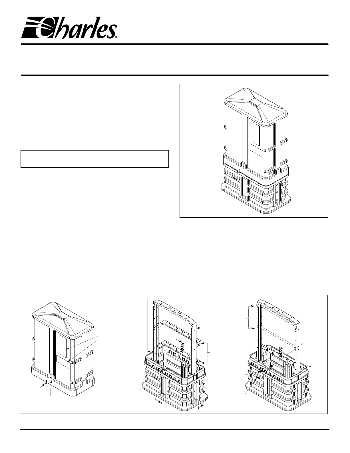
above-ground enclosure. See Figure 1 for a typical CMPH model, Table 5
for general information on products in this series, or call Charles Indus-
tries (see Part 2) to request more information.
- NOTE -
Hereafter the Charles Multi-Purpose Housing will be commonly referred to as
the “CMPH” or “enclosure.”
1.2 Document Status
Whenever this document is updated, the reason will be stated in this para-
graph. The Fourth Printing removes “Optional Stake Mounting”. Stake
mounting is required for best performance.
1.3 Product Purpose and Description
The CMPH is a non-metallic, two-piece, rectangular, OSP enclosure that
offers easy installation, superior structural strength, 360_technician ac-
cess, generous internal equipment and cable storage capacity, and
protection against corrosion, floods, fire, weather, dirt, insects, intrusion,
dents and impact. The CMPH contains a base, a dome, and internal frame-
work. The base has corrugated or ribbed walls, internal, dual-purpose,
molded-in, channel grooves (which accept most metallic stakes as well as
the vertical channels of the internal framework, see Figure 2), an open top,
and an open bottom. Easy replacement installations and easy underground
cable access is provided via the open bottom. The top piece of the CMPH
is the dome, designed to overlap the base for a flood-protective bell-jar ef-
fect. Inside the CMPH, sturdy framework with splice bars and brackets
provides versatile mounting options for equipment (such as fiber optic
Figure 1. Typical CMPH Enclosure, Closed View
splice closures, terminal blocks, and cases) as well as storage, contain-
ment, and attachment options for various types, sizes, and quantities of
conduit, innerduct, and cabling.
1.4 Product Mounting Type and Location
The CMPH is an above-grade enclosure, the base of which is typically in-
stalled in a trench or hole in the ground up to the base’s ground line indicator.
The ribbed or corrugated base walls provide excellent stability in most soil
types. The dome mounts on the base and protects all equipment installed or
Figure 2. Typical CMPH Enclosures, Dome Removed Views
Dome
Base
Inside
Framework
Fiber cable
management
offset brackets
Channel
Hasp
(see Step 26)
Ground
Plate
Hasp
(optional)
Base
collar
Copper cable
management
bars
Fiber-type Copper-type
Label or
decal
areas
Self-locking latch
(secured via cup‐washer screw)
Ground line
indicator
Base latch
(lock
catch)
030‐300377 Rev. A Section LTCMPH-75-802
0316P4 Page 2 of 5
mounted inside the CMPH. Stake mounting is obtainable via molded channel
grooves, which are located at the center of each interior side wall of the base.
These grooves accept most new and existing enclosures’ mounting stakes.
1.5 Installation
See Table 1 to perform a new CMPH enclosure installation. Table 2 de-
scribes a new CMPH installation with stakes, and Table 3 describes an
installation to replace an existing enclosure (rehabilitation installation).
- GROUNDING WARNINGS -
Always follow local codes and company practices for performing proper cable
and site bonding and grounding, and perform all bonding and grounding prior
to other electrical, fiber, and communications connections.
- CABLE DAMAGE WARNINGS -
Be careful not to damage any buried cables or service wires while digging either
to expose cables or to prepare a hole or trench, or while driving stakes.
Buffer tubes and fibers are sensitive to excessive bending, pulling, and crushing
forces. To avoid kinking of buffer tubes and fiber damage or breakage, exercise
great care when working with fiber, and do not exceed or violate minimum bend
radius requirements for fibers, buffer tubes, and cables.
- BODILY HARM WARNINGS -
Risk of serious eye damage! Never look into the end of a fiber optic line or circuit
nor use a magnifier in the presence of laser light or radiation. Always exercise
caution when installing, testing, or performing maintenance on live circuits. If eye
exposure to laser light or radiation has occurred or is suspected, immediately seek
medical treatment by a professional eye care physician.
Shards and cleaved glass fibers are very sharp and can easily pierce the skin. Do
not let cut pieces of fiber stick to your clothing or drop in the work area where they
can later cause injury. Use tweezers to pick up cut or broken pieces of glass fibers
and place them in a container specifically meant for this purpose.
The corrugated metal or armor that may be present in the feed cable is very sharp
at the cut or exposed edges. Extreme caution should be taken to prevent personal
injury. Protective work gloves are recommended when handling armored cable.
Cable and fiber cleaning solvents may contain hazardous materials or harmful
ingredients. Always read and follow the manufacturer’s precautions, warnings,
and instructions when working with cleaning solvents or products.
Table 1. Installing a New CMPH Enclosure
Step # Instruction
1. hObtain tools, materials and equipment. Gather the following equipment to
perform the CMPH installation.
h216 tool or can wrench hTrenching and digging equipment and tools
hCharles CMPH model hCable grounding materials and tools
hScissors, knife or snips hCable opening and management equipment
hLevel hClean, dry, pea gravel (3/8"‐5/8" diameter)
hMeasuring tape hConduit and conduit caps (optional)
hSoil tamping tool(s) hWrenches or socket set
hSoil for backfill hSite cleanup tools
2. hPrepare trench. Do not damage any buried cables or wires while
digging. Dig and prepare the cable trench, per company practice.
3. hPlace cables (or conduit or innerduct) in trench. Follow company
practice to lay, place, and cut any cables and innerduct or conduit.
4. hUnpack and inspect equipment. Remove the CMPH from its packaging.
Inspect the unit upon delivery; if damaged in transit, report the damage to the
shipping company.
5. hDisengage the CMPH lock. Unlock the
CMPH using a 216 tool or can wrench
at the front hex nut‐in‐cup washer
screw; turn the cup‐washer screw
counterclockwise approximately 1/8
turn until it stops. Hold in this position,
then lift the dome up approximately 1"
(enough to disengage the self‐locking
latch) by grasping and lifting the
molded side rail.
Cup‐washer screw
inside dome self‐locking latch
216
Tool
6. hRemove the dome.
Set aside the can
wrench after slightly
lifting the dome, then
use both hands to
grasp a side rail (rib)
with each hand and
completely lift off the
dome from the base.
Set aside the dome for
later use.
Pull up
on ribs
Pull up
on ribs
7. hLocate and remove red plastic bag. Remove the red bag labeled “moisture
barrier" included with the CMPH. Set it aside for later use.
8. hOptional - Replacement or rehabilitation mountings only. For
applications to replace old enclosures, continue with the steps in Table 3.
9. hDetermine and mark base installation location. To determine exactly
where to place the base in the trench, use the base itself as a positioning
template by placing it up over the top of the conduit, innerduct, or cables
(route the cables through the base) and lowering the base to the ground.
Analyze the site and position the base at its proposed final orientation and
horizontal positioning in the trench or hole and adjust accordingly. Mark this
proposed final spot by removing a shallow layer of top soil from around the
outside perimeter of the base about 2‐4 inches wider than the base. Set the
base aside.
10. hDig a hole for the base. Caution: Avoid damaging buried cables, wires,
innerduct, conduit or ground equipment whenever digging. At and
within the marked perimeter boundary, dig straight down to a depth of 9
inches. Do not dig too deep.
11. hStake mountings. Refer to Table 2 for instructions to install mounting
stakes in Table 2.
12. hPut base in hole or trench and route cable(s) through base. Route the
cables and conduit or innerduct up through the bottom of the base, then put
the base in the prepared hole or trench.
Note: Ensure the base location allows technician access to the lock and any
equipment installed or to be installed in the CMPH.
13. hVerify proper base depth. Before backfilling, verify the base is at the proper
depth, approximately 9 inches deep. Rest the base on solid or well‐tamped
soil when measuring this distance. Verify the base ground line indicator is at
the same level as the final‐grade ground line. Remove, add, or tamp more
soil as necessary.
14. hLevel the base. Verify that the base is level. Check the level in both
dimensions; front to back, and side to side. Make any needed base‐bottom
soil adjustments to bring the base to a level position.
15. hPrepare earth ground. Always
follow local codes and company
practice when preparing earth
ground and when grounding
cables or equipment. If an earth
ground is not present at the
CMPH site and local code or
practice requires an earth
ground, prepare one now. Attach
the earth ground to the CMPH's
ground lug on the ground plate
(Step 21) using a ground wire of
proper gauge, per company
practice.

030‐300377 Rev. A Section LTCMPH-75-802
0316P4 Page 3 of 5
16. h
Position the base on top
of the gravel and level the
base. Alternately backfill
the base on the inside
first then the outside,
tamping the soil as it is
added. This equalizes the
pressure inside/outside
the base and makes the
base more stable. The
backfill on the outside of
the base should be even
with the Ground Line on
the front of the base.
Inside, add backfill soil to
a point midway between
the first and second ribs.
2 to 3" gravel inside
the base (Step 18)
Base
Top
ÏÏÏÏÏÏÏÏÏ
ÏÏÏÏÏÏÏÏÏ
ÏÏÏÏÏÏÏÏÏ
ÏÏÏÏÏÏÏÏÏ
ÏÏÏÏÏÏÏÏÏ
ÎÎÎÎÎÎ
ÎÎÎÎÎÎ
ËËËËËË
Soil
Pea Gravel
Soil
Backfill and tamp inside/outside the base. Once the hole has been dug to
the proper depth, a layer of pea rock /gravel must be placed at the bottom of
the hole. Note: The base can be leveled more easily if it is placed on
gravel first.
8"
7"
Side View
Moisture
Barrier (see
Step 17)
Base
Bottom
Ground
Line
2"
above
vapor
barrier
1st
Rib
of
Base
ÎÎÎÎÎÎÎÎÎ
ÎÎÎÎÎÎÎÎÎ
Gravel layer
17. hPlace the red plastic moisture barrier. The provided moisture barrier sheet
or bag must be placed on top of the tamped backfill soil inside the base. If it is
supplied as a bag, cut the sides so it can be spread over the backfill soil. Bring
it to the edges of the base so it covers as much of the backfill as possible. The
sheet can be cut to fit around any duct or cable entering the base, or an X can
be cut in the center to allow the sheet to be fitted over the cable or conduits.
The sheet serves to prevent excessive moisture from entering the CMPH.
Failure to use the plastic moisture barrier on top of the soil significantly
increases the risk of condensation inside the pedestal.
18. hAdd gravel to the inside of the base. Pour approximately 2 to 3 inches of
5/8", or smaller, pea rock or gravel into the base up to the second rib or 2
inches below any innerduct or conduit opening. Keep the duct openings
sealed when adding gravel. Spread out and level the gravel.
19. hEnd of base installation - determine next procedure. If cable work will
now be performed, continue with the next steps and consult local practices
and equipment manufacturer instructions for the proper procedures. If
further cable work will NOT be performed at this time, skip to Step 24 to
close the CMPH enclosure.
20. hPerform cable routing and mounting. Per company practice and local
codes, perform all cable routing, mounting, and management procedures.
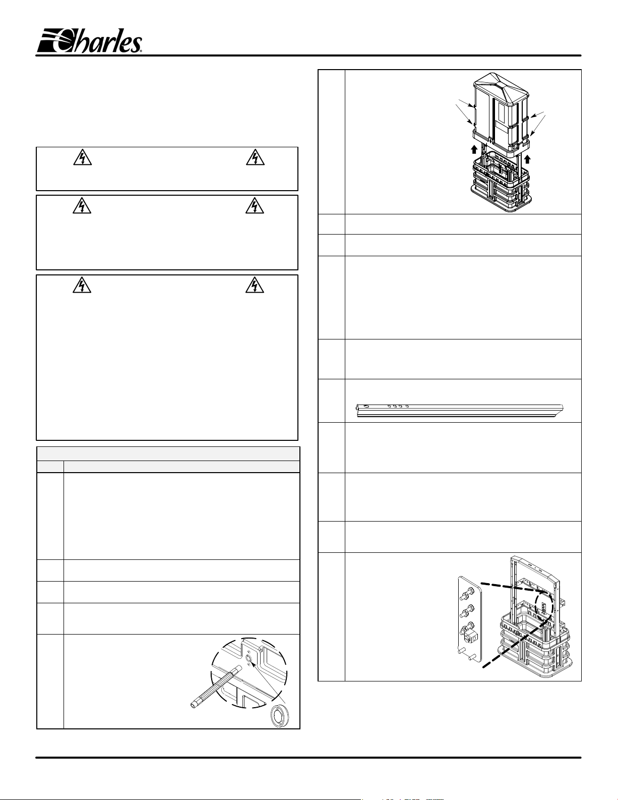
21. hBond and strain‐relief the cables.
Ground or bond the cable(s) to the
ground posts provided on the ground
plate. Perform cable strain relief and
bonding per company practice. Attach earth ground
to ground lug
Attach cable bond
straps to posts
Ground Plate
Posts to attach plate to ground bracket
22. hFinish cable work & equipment mounting. Per company practice, perform
all cable opening and splicing procedures, and equipment mountings and
connections.
23. hRe‐check cable management. Verify all equipment and cabling is organized
and will not contact the interior walls of the dome when installed (keep items
at least 1" from the vertical plane of the base collar). This assures safe and
smooth dome placement.
24. hInstall dome. Locate the dome and lift it
up and over the interior framework and
equipment. When replacing the dome,
make sure the lock side of the dome is
facing the catch side of the base. Lower
the dome until it overlaps and
self‐latches to the base. Lower dome
onto base,
latch will
self‐lock
Align bottom of
dome with top
of base
25. hVerify the CMPH is locked. The
dome design allows the dome to
self‐lock on the base. Verify the
dome is locked by attempting to
lift the dome.
26. h(Optional) Padlock the CMPH. For models equipped with an optional
hasp, the CMPH also can be locked by inserting a padlock through the
holes in the hasp provided at the front of the enclosure.
Hasp for padlock
(orderable option)
27. hLabel outer dome. Place all ID/warning labels on the dome, per company
practice.
28. hEnd of CMPH placement. Clean up site. If no more equipment or cable
work will be performed at this time, clean up the site, fill and tamp any
trenches, replace any removed sod, restore the landscape to it's original
condition, pick up all equipment, and optionally leave this document inside
the CMPH for future reference.
Table 2. Installing the CMPH with New Charles Stakes
Step # Instructions
Charles offers some CMPH models that include 2mounting stakes (either 30", 36", or 42" long).
All stakes have identical hole patterns. This table describes how to install these models.
1. hPrepare the CMPH, trench, and cable. Perform Steps 1‐10 of Table 1 to
open the enclosure and prepare the hole or trench and the cables or
conduit. Verify the base installation site is ready and suitable for metallic
stakes.
2. hRemove stakes from
CMPH framework. Two
mounting stakes are
packed with the CMPH;
detach them from the base
lag bolts by removing the
nuts and washers which
secure them. Take care to
retain the hardware which
will be re‐used in
subsequent steps.
Remove but retain the nuts
that secure the stakes to
the inside of the enclosure
Fiber‐type bracket
(note offset depth)
030‐300377 Rev. A Section LTCMPH-75-802
0316P4 Page 4 of 5
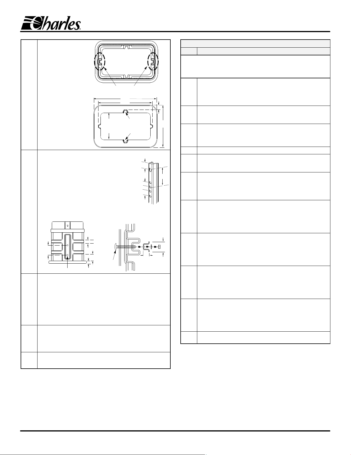
3. hDetermine which
grooves to use for
stakes. The base
contains a molded‐in
dual‐purpose groove
at the center of each
wall to accept the
U‐shaped mounting
stakes (as well as the
U‐shaped vertical
channels of the
frame). Per local
company practice
and site conditions,
select two wall
grooves that are
appropriate for stake
attachment purposes
(the grooves on the
shorter side walls are
typically used).
Base
Bottom
View
Open
Inside
Area
Alternate Mounting
Grooves (generally used
in vault applications)
25.5"
29.5"
2"
1.5"
2"
17"
Base
Top
View
Preferred U-shaped channel
grooves for mounting stakes
4. h
1.6”
1.1”
Top View
of Stake
Set stake
into groove
Attach stakes to grooves in base. Set the base on the
ground or a raised surface to access the grooves through
the base bottom. On the inside of the base, remove the
nuts and washers from the bolts (which are 4" apart) that
secure the frame channels in place. On the mounting
stake, the distance between the first and third hole down
from the top of the stake is 4". Insert the top of the stake
into the base, rotate the stake so it will fit properly into the
base groove (so the perimeters match), align the stake
holes with the bolts in the base, and set the stake in place
in the groove. Re‐install the lock washers and nuts that
were removed to secure both the mounting stake and
frame channel in place. Repeat for the other stake.
Base Side View
4
"
1
"
1.3
"
Bolt for frame channel and stakes
4
"
Charles
Stake
Top View of Base
Wall at Groove
1.125”
3”
1”
1”
1.2”
Carriage
Bolt
3
"
5. hVerify hole or trench accommodates stake length. Lift the base and
attempt to place it back in place in the trench or hole. If the trench is deep
enough to accommodate the length of stake protruding from the bottom of
the base, skip the rest of this step. If the hole or trench is not deep enough
to accept the stakes, and the weight of the base is not enough to drive the
stakes the length needed to allow the base to rest at its proper depth, then
once again use the base as a template to mark the exact stake locations in
the ground where more soil must be removed. Remove the base from the
hole, and at the stake‐hole indentations, dig down just enough to
accommodate the length of the stake.
6. hSet base in place, bring cables into base. When the hole is deep enough
for the stakes, again lift the base by its walls or ribs and set it back into the
hole, being sure to enclose or encompass within the base all cables,
innerduct, conduit or equipment present at the site and intended for storage
inside the enclosure.
7. hFinish the installation. Perform Steps 13 through 28 in Table 1 to finish
the installation. Be sure to backfill and firmly tamp soil into the stake holes
when backfilling.
Table 3. Installing Replacement or Rehabilitation Enclosures
Step # Instructions
The Charles CMPH has the same footprint as the UPC 1200 series. These instructions
describe how to replace a UPC 1200 with a Charles CMPH. To replace enclosures with
smaller footprints, remove the smaller enclosure and dig a wider hole, as described in
Step 9 of Table 1.
1. hPrepare the base, trench, and cables. Locate the old or existing
enclosure (such as the UPC 1200 series) to be replaced. Perform Steps 1‐7
of Table 1 to prepare the new Charles CMPH enclosure, the hole or trench,
and the cables or conduit (skip Steps 2‐3 if trenching and new cable
placement is not required).
2. hDig around existing enclosure. Remove the dirt from around the existing
enclosure. Dig deep enough to allow the enclosure to be lifted and
removed.
3. hPrepare existing enclosure for removal. Remove the bottom panels of
the UPC 1200. Locate the mounting stakes and remove the nuts and bolts
from them. Remove all attachments to the enclosure, including cable
supports and tie wraps, bonding connections, and grounding connections.
4. hRemove the old enclosure. Completely remove the existing enclosure.
5. hProtect cables and connections. Per company practice, wrap the existing
splice as tightly as possible without damaging the wire (or fiber)
connections.
6. hAnalyze condition of existing mounting stakes. Inspect the existing
mounting stakes for possible re‐use. If they are deteriorated, bent, out of
alignment, or have a hole pattern that will not work with the Charles CMPH
base, carefully remove the stakes and install new ones per company
practice (consult Table 2 if desired).
7. hOptional - remove the CMPH's horizontal splice bars and/or ground
bracket. Analyze whether or not it will be necessary to temporarily remove
any of the CMPH's internal, horizontal, supportive splice bars or brackets in
order to fit the existing cabling, connections, splices, and equipment into
the CMPH during the base installation. After base installation, re‐attach the
bars and brackets (Step 10).
8. hSet base in place. Lift the base over the existing cabling and equipment,
and route the wrapped splice and all equipment up through the base bottom
while lowering the base to the bottom of the hole. If the existing stakes were
used, verify they are inside the base. If new stakes were attached to the
base, insure the hole accommodates them. Perform Steps 13‐14 of Table 1
for the proper base depth and level.
9. hAttach base to re‐used stakes. Remove the nuts and washers from the 4
bolts located inside the CMPH base that secure the frame channels in
place (2 bolts on each side, 4" apart). Manipulate the base and/or stake
tops so the re‐used stakes fit into the preformed stake grooves in the base
walls. Align the base bolts with the stake holes, and re‐attach the washers
and nuts onto the bolts. Firmly tighten nuts.
10. hAttach cables to bars and brackets. If the splice bars or brackets were
removed, re‐install them now in the best positions to support (and ground)
the equipment. Per company practice, attach or mount all cables and
equipment to the internal framework (bars, brackets) of the CMPH.
Re‐attach any grounding, bonding, and cable connections previously
unattached to remove the old enclosure.
11. hClose the CMPH and clean the site. Perform Steps 23 to 28 of Table 1 to
close the CMPH and restore the site to its previous condition.
2. CUSTOMER TECHNICAL SERVICE
If technical assistance or customer service is required, contact Charles Indus-
tries by calling or using one of the following options:
847-806-8500 (Tech. Service local) 847-806-6300 (Customer Service)
800-607-8500 (Tech. Service toll-free) 847-806-6653 (Customer Service FAX)

030‐300377 Rev. A Section LTCMPH-75-802
0316P4 Page 5 of 5
Table 4. Physical Specifications
Feature U.S. Metric
Height, overall 47 in. 119.4 cm
Height, base only, incl. collar 17 in. 43.2 cm
Height, dome only 33 in. 83.8 cm
Height, internal framework 30 in. 76.2 cm
Height, base bottom to ground line 9 in. 22.9
Depth, base (at wider footprint) 17 in. 43.2 cm
Depth, dome 14.5 in. 36.8 cm
Width, base (at wider footprint) 29.5 in. 75 cm
Width, dome 27 in. 68.6 cm
Weight, dome 22 lbs. 10 Kg
Weight, base, fiber‐bracketry models 29 lbs. 13.1 Kg
Weight, base, copper‐bracketry models 27 lbs. 12.3 Kg
Weight, two 30" stakes 5 lbs. 2.2 Kg
Weight, two 36" stakes 6 lbs. 2.7 Kg
Weight, two 42" stakes 7 lbs. 3.2 Kg
NOTE: All dimensions and weights are approximate.
Table 5. Model Number Ordering Information & Options
Model # Description
CMPH‐75ABCD Charles Multi‐Purpose Housing. All sturdy self‐locking CMPH
models come with a polyethylene base, an overlapping
polyethylene dome, and internal metallic framework for mounting
equipment and cabling, a ground plate with a ground lug and
bond posts, instructions, and a plastic moisture‐barrier sheet.
Order model CMPH‐75 A B C D , where A, B, C, or D
represents one of the features as listed below.
A (stake size): 0 = No stakes. 1 = 30" stakes. 2 = 36" stakes. 3 = 42"
stakes.
B (bar or bracket type): 0 = Standard copper type. F = Fiber type (offset, see
Step 2 Table 2).
C (material): F = Flame retardant. N = Non‐flame retardant.
D (hasp): H = Hasp for padlock for additional security.
Hasp
Optional Equipment for Use with CMPHs
CMPH‐FOBRKT Kit containing one offset
bracket and mounting
hardware, typically used
for fiber applications.
CMPH‐BOND10 Package of 10 ground plates, each plate contains a
ground lug and 6 bond posts. Attaches to internal,
horizontal, ground bracket.
CMPH‐SPBAR10 Package of 10 splice bars, typically used for copper applications.
CKPL‐99 Mounting bracket
kit for either one
12‐pair
or one 25‐pair
terminal block.
Includes 2
brackets and
mounting
hardware.
12‐pair terminal
block (not included)
bracket
Various replacement and optional parts are available, including bracket kits for vault‐mounting. Contact Charles
Industries for more information.
Table of contents
Other Charles Enclosure manuals


Popular Enclosure manuals by other brands


CRU
CRU DataPort SecureDock quick start guide

Outback Power Systems
Outback Power Systems OBE-3-FT installation guide

Adaptec
Adaptec SANbloc S50 Quick install guide

Icy Box
Icy Box IB-1820M-C31 manual

Extron electronics
Extron electronics MediaLink MLM-WB+ user manual

2B Technologies
2B Technologies 106 installation manual