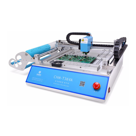
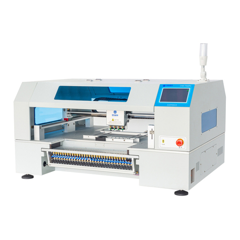
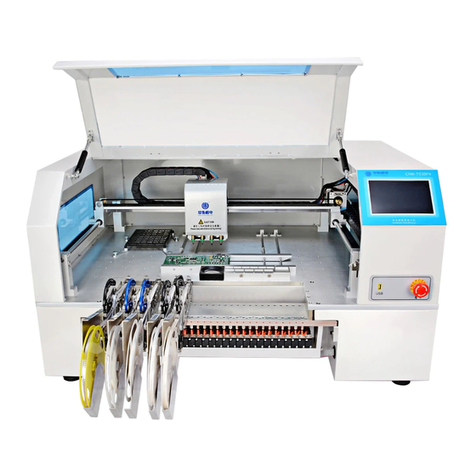
Charmhigh CHM-T48VB User manual

长沙常衡机电设备有限公司
http://www.charmhigh.net
1
Charmhigh Automatic Chip
Mounter(CHM-T48VB)Operating
Manual
2016
CHARMHIGH TECHOLOGY LIMITED
Technology Versus Future-V1.0-2016
2016-06-01

Charmhigh-V1.0-2016 |
2
All Rights Reserved
Catalogue
1. REVISION HISTORY......................................................................................................... 4
2. INSTALL THE MACHINE .................................................................................................. 5
3. PRODUCT LIST................................................................................................................. 6
4. HARDWARE REQUIREMENTS AND COMPATIBLE SOFTWARE................................. 7
4.1. HARDWARE REQUIREMENTS.......................................................................................... 7
4.2. COMPATIBLE SOFTWARE ............................................................................................... 7
5. NOTICES ........................................................................................................................... 8
6. TECHNICAL PARAMETERS ............................................................................................ 9
7. MECHANICAL STRUCTURE.......................................................................................... 10
8. BOOT THE MACHINE..................................................................................................... 12
9. RUN ................................................................................................................................. 13
9.1. EDIT WORK FILE......................................................................................................... 13
9.1.1. Component ....................................................................................................... 14
9.1.2. Material Stack ................................................................................................... 17
9.1.3. Batch................................................................................................................. 20
9.1.4. IC Tray............................................................................................................... 23
9.1.5. PCB Calibration ................................................................................................ 24
9.2. LOAD WORK FILE........................................................................................................ 26
10. TEST ............................................................................................................................ 28
11. SET .............................................................................................................................. 30
11.1. SYSTEM SET........................................................................................................... 31
11.2. VACUUM DETECTION SET........................................................................................ 34
11.3. BACKUP/RESTORE.................................................................................................. 35
12. FILE.............................................................................................................................. 37
12.1. GENERATE CSV FILE.............................................................................................. 37
12.1.1. By Altium Designer........................................................................................ 37
12.1.2. By Protel........................................................................................................ 39
12.2. FILE CONVERT........................................................................................................ 42
12.2.1. Material Stack ............................................................................................... 44
12.2.2. Component.................................................................................................... 44
12.2.3. Batch............................................................................................................. 45
13. LOG.............................................................................................................................. 47
14. SYSTEM LOG.............................................................................................................. 48
15. QUICK START............................................................................................................. 48

Charmhigh-V1.0-2016 |
4
All Rights Reserved
1. Revision History
No.
Date
Description
Version
1
2016-06-01
Create document
V1.0

Charmhigh-V1.0-2016 |
5
All Rights Reserved
2. Install the Machine
Open the packing cases, take out the SMT machine, placed it on a strong table;
Check if the machine is in good condition, check the list of products, if you have
any questions please contact us;
Please read this manual carefully before use SMT machine;
There's any problem in use, welcome to contact.

Charmhigh-V1.0-2016 |
6
All Rights Reserved
3. Product List
No.
Parts
Quantity
Remarks
1
SMT machine
1
-
2
nozzles
4
503,504,505,506
3
USB flash disk
1
8G
4
power cord
1
-

Charmhigh-V1.0-2016 |
7
All Rights Reserved
4. Hardware Requirements and Compatible Software
4.1. Hardware Requirements
All equipment are built-in, don't need other external devices.
4.2. Compatible Software
Compatible with Protel99se,Altium Designer.

Charmhigh-V1.0-2016 |
8
All Rights Reserved
5. Notices
(1) Keep the machine away from humidity and dust, otherwise may cause electric
shock or fire;
(2) Do not place the machine in the platform of instability or tilted, otherwise the
vibration of the machine when working may lead to lower precision, even personal
injury caused by overturned;
(3) Don't disassembling machine, or may be led to the decrease of the accuracy or
machine damage;
(4) Don't use hand to touch the moving parts, otherwise it may damage the machine
or cause personal injury;
(5) New machine components containing volatile substances, it need to maintain
good ventilation in the first few days using;
(6) The power cord can only be used for the machine, otherwise may damage the
other electrical appliances;
(7) Ensure the power supply meet machine nominal requirements;
(8) Ensure the power supply socket with good grounding;
(9) Keep the machine away from flammable and explosive goods;
(10) Place the nozzles and other small accessories in out of the reach of infants and
young children;
(11) Don't let the pull needle in the stretched state for a long time, or it could be
damaged;
(12) Don't put machine direct exposure to sunlight or bright light, otherwise may cause
the machine precision reduce or damage to the machine.

Charmhigh-V1.0-2016 |
9
All Rights Reserved
6. Technical Parameters
model
CHM-T48VB
PCB area
10mm×10mm~355mm×355mm
X,Y axis stroke
510×460mm
Z axis stroke
15mm
number of nozzle
2
material stack number
ordinary material stack 58, IC material stack up to 14
visual support
dual cameras
Motor drive
Closed-loop servo high voltage drive system(Ensure the
accuracy of operation)
Z axis back position
detection
Yes
Pull needle auto return
Yes
Leak detection method
Vacuum detection、Visual inspection
LCD Screen
7 inch Industrial LCD screen
Board
Independent research and development of industrial computer
motherboard
System
Embedded Linux system
need external air pump
no(built-in mute air pump)
need external PC
No need
power supply
220V(110V), 50Hz
power
250W
weight
65Kg
volume of packaging
0.41m3

Charmhigh-V1.0-2016 |
10
All Rights Reserved
7. Mechanical Structure
The figure below shows the machine structure as a whole.
tape placing
area A
nozzle
pull needle
ordinary material
stack A
Belt receiving
wheel A
IC tray (PCB) clamping area
down camera
power
PCB clamping area
up camera
touch screen
USB emergency stop
power switch
IC material stack
tape placing
area A
ordinary material
stack B
Belt receiving wheel B
Figure.7-1
(1) Nozzle: Support two nozzles, the nozzle 1 is on the left, nozzle 2 is on the right,
used for absorbing materials;
(2) Pull needle: Used for pulling tape, note, don't let the pull needle in the stretched
state for a long time, or it could be damaged;
(3) Down camera: Used for observing the material stack, PCB and components;
(4) Up camera: Used for calibrating the components position, angle, so as to improve
placement accuracy;
(5) IC tray (PCB) clamping area: Used for fixing the IC tray or PCB;
(6) PCB clamping area: Used for fixing PCB, let PCB close to left, top spring should
be compacted;
(7) Ordinary material stack A\B: Place tape packaging materials;
(8) Belt receiving wheel A\B: Used for collecting film;
(9) Tape placing area A\B: Used for placing tape;
(10)IC material stack: Used for placing the larger IC;
(11)Touch screen: Used for manipulating and control the machine;
(12)USB interface: Used for connecting the USB storage device;
(13)Emergency stop switch: Emergency stop after press down, machine normal

Charmhigh-V1.0-2016 |
11
All Rights Reserved
work when clockwise rotation and bounce;
(14)Power switch: Note, open this button to boot, shutdown should first close the
software through the touch screen, and then close the button.

Charmhigh-V1.0-2016 |
12
All Rights Reserved
8. Boot the Machine
Open the machine power switch, wait for the machine to self check and loading the
operating system, when machine start complete, display screen as shown below.
Figure.8-1
(1) Alarm:Used for viewing current alarm and cause;
(2) Run: Used for loading working files and control the machine running etc.;
(3) Test: Used for testing each function module respectively;
(4) Set: Used for setting various parameters that machine work required;
(5) Log: Used for viewing the record information;
(6) System Log: Used for viewing the log of system;
(7) Files: Used for managing and convert work file.

Charmhigh-V1.0-2016 |
13
All Rights Reserved
9. Run
The machine needs to select a work file to run, from the main screen, click on the run
button to enter the screen as shown below, through this screen can manage work file.
Figure.9-1
(1) Work file list: The middle of the screen displays a list of existing work files in the
system, click to select the work file, the upward double arrow on the right used for
paging up, upward single arrow used for selecting previous line, downward arrow
vice versa.
(2) New: Create a new work file;
(3) Delete: Delete the selected work file;
(4) Edit: Edit the selected work file;
(5) Load: Load the selected work file to run;
(6) Back: Click left arrow button on the upper right corner of the screen to return to
the previous level screen, other screen similarly.
9.1. Edit Work File
The work file editing screen shown as below, can edit component, material stack,
batch, IC tray and PCB calibration respectively.

Charmhigh-V1.0-2016 |
14
All Rights Reserved
Figure.9-2
9.1.1.Component
The screen as shown above, used for managing device in PCB.
(1) Component list: Show all components contained in the selected work file, green
indicates enables vision calibration, orange indicates disable vacuum testing,
purple indicates enables vision calibration and disable vacuum testing, gray
indicates skip the device;
(2) Add: Add a component to the end of the list;
(3) Insert: Insert a new component before the currently selected row;
(4) Delete: Delete the selected component;
(5) Edit: To edit the selected component, see below for details;
(6) Save: If you edit the component in the list, the save button will flash, prompt the
information changed and has not been saved yet, click to save and stop flash.
9.1.1.1. Edit
The popup screen as shown below, the top left of the screen displays the current
component‟s line number (start from 0),the arrows on both sides, used for selecting a
component before or after, also can click the middle button popup keyboard to input
device line number directly.

Charmhigh-V1.0-2016 |
15
All Rights Reserved
Figure.9-3
(1) Comp. ID: Set component ID number, component ID number can not repeat in
the same work file;
(2) MStack: Set the specified component‟s material stack, when specifying a new
material stack, the material stack list in work file will automatically add a new
similar material stack;
(3) Speed: Set the component speed, set to 0 indicate use system speed, tips,
reduce speed properly when mount IC can improve the accuracy, e.g. 50%;
(4) Height: Set component height, smaller values represent lower height, and the
nozzle down more; Note,in order to adapt the 1.6 mm height PCB board, the
factory default height is 0.5 mm. Do some adjust for different thickness boards.
(5) Angle: Set component rotation angle, counterclockwise is positive, clockwise is
negative;
(6) Designator: Component designate information, such as R1, R2, C1, U1 etc.;
(7) Comments: Component annotation information, such as 0402,0805;
(8) MHead: Select nozzle, e.g. nozzle 1;
(9) Coord. X: Component coordinate X, generally do not need to modify if it is
generated in work file;
(10) Coord. Y: Component coordinate Y, generally do not need to modify if it is
generated in work file;
(11) Skip comp.: Check indicate not mount;
(12) Vacuum detect: Check indicate not throw material due to vacuum insufficient,

Charmhigh-V1.0-2016 |
16
All Rights Reserved
note, no material detection still effective, i.e. if the current position is not get the
material, it will do it one more time, if still failed then pull the tape one time and try
two times, if pull tape two consecutive times (in 3 position, total try 6 times) all
failed, then the machine alarm and stop, we suggest open this function when
mount such as cylindrical component;
(13) Enable vision: Check indicate calibrate component with vision, note, enable
vision can improve precision when mount IC;
(14) Coord. set: Setting component coordinate use down camera or nozzle, see
details below.
9.1.1.2. Coordinate Setting
Screen shown as below.
Figure.9-4
(1) Coordinate: Coordinate offset display in the upper left corner;
(2) MHead\Vision: Switchover coordinate set mode among nozzle and vision, the
figure below shows the screen that set coordinate by nozzle, in this mode user
need to check position by eye;

Charmhigh-V1.0-2016 |
17
All Rights Reserved
Figure.9-5
(3) Move: In the left side of the window four arrows control the mount head moving
in four directions respectively, movement speed can changed by H/L button, L
indicate low speed, H indicate high speed;
(4) Enlarge: zoom up the image;
(5) Find Target: Locating component position automatically, principle explains as
follows, the algorithm search from the image center to around, the first searched
close graph is deemed to the target which marked with red rectangle. Note, the
border of the target must be clear and closed, silk printing is found generally;
capture target is just auxiliary function, silk printing position not always be the
right position of component since the deviation of process technology, user
should set coordinate according to the position of footprint;
(6) Auto. center: Move nozzle to the center of target if target was captured;
(7) MHead n(n is MHead number): When use nozzle to positioning, click this button
then specified nozzle press down, for the convenience of observation;
(8) Apply: Click to apply changes.
9.1.2.Material Stack
Screen show as below, in this page can manage different kinds of component‟s place
position.

Charmhigh-V1.0-2016 |
18
All Rights Reserved
Figure.9-6
(1) Material stack list: Display all material stack that the work file contained;
(2) Add: Add a new one to the end of the list; tape packaged material use ID 1 to 29,
bulk IC use ID 60 to 79, IC tray use ID 80 to 99(see details below);
(3) Insert: Insert a new one to the position that before current selected material stack;
(4) Delete: Delete selected material stack, note, all of components that use this
material stack in the component list will be deleted too;
(5) Edit: Edit selected material stack, screen show as below.
Figure.9-7

Charmhigh-V1.0-2016 |
19
All Rights Reserved
a) Stack ID: Set current material stack ID, value can‟t repeat, all of components‟ ID
that use this material stack in the component list will be changed too;
b) Feed: The center distance between two successive components in the tape, unit
is millimeter;
c) Ec size X\Y: The size of components in this stack, unit is millimeter;
d) X\Y offset: Material stack coordinate adjustment;
e) Height: Functionally just like corresponding item in component edit, all of
relevant component will be changed;
f) Speed: Functionally just like corresponding item in component edit, all of
relevant component will be changed;
g) Comments: Set material stack comments;
h) Skip comp.: Functionally just like corresponding item in component edit, all of
relevant component will be changed;
i) Vacuum detect: Functionally just like corresponding item in component edit, all
of relevant component will be changed;
j) Enable vision: Functionally just like corresponding item in component edit, all of
relevant component will be changed;
k) Coord. set: Functionally just like corresponding item in component edit, see
figure below, there will appear a pull needle button in the top right corner of the
window when set coordinate by nozzle, click it then machine will pull tape one
time, in order to make the component in a certain place, then calibrating the feed
place of material by camera or nozzle, see figure below, adjusting the tape let the
red circle touches the blue line, the place of green rectangle is just the suggested
feed place.

Charmhigh-V1.0-2016 |
20
All Rights Reserved
Figure.9-8
Figure.9-9
9.1.3.Batch
Batch is that splicing a number of same PCBs to mount together, but just need one
Table of contents
Other Charmhigh Industrial Equipment manuals

