Charmhigh CHM-T560P4 User manual

长沙常衡机电设备有限公司
http://www.charmhigh.net
1
2016/2/19
Technology Versus Future | CHARMHIGH TECHNOLOGY LIMITED
CHM-T560P4
PICK AND PLACE MACHINE
USER MANUAL V2.5-2.0-1.0

1
CATALOGUE
1. VERSION UPDATE ........................................................................................................... 2
2. SAFETY MATTERS........................................................................................................... 3
3. MAIN PARAMETERS........................................................................................................ 4
4. MACHINE INTRO.............................................................................................................. 5
5. START ............................................................................................................................... 7
6. RUN ................................................................................................................................... 8
6.1. EDIT WORK FILE............................................................................................................ 8
6.1.1. Component edit................................................................................................... 9
6.1.2. Material Stack Edit............................................................................................ 12
6.1.3. IC Tray edit........................................................................................................ 14
6.1.4. Panel edit.......................................................................................................... 16
6.1.5. PCB calibrate.................................................................................................... 17
6.2. RUN........................................................................................................................... 19
7. TEST................................................................................................................................ 21
8. SET .................................................................................................................................. 22
8.1. SYSTEM SET............................................................................................................... 23
8.3. BACKUPAND RECOVERY.............................................................................................. 25
9. FILE MANAGE ................................................................................................................ 26
9.1. GENERATE CSV FILE .................................................................................................. 26
9.1.1 BY ALTIUM DESIGNER ................................................................................................. 26
9.2. FILE CONVERT ............................................................................................................ 28
9.2.1. CSV File............................................................................................................ 29
9.2.2. Material stack station list................................................................................... 30
9.2.3. Components list................................................................................................ 31
9.2.4. Batch.....................................................................................
错误!未定义书签。
10. LOG.............................................................................................................................. 32
11. SYSTEM LOG.............................................................................................................. 33
12. MAINTENANCE........................................................................................................... 34
3. WARRANTY .................................................................................................................... 35
4. CONTACT US......................................................................................错误!未定义书签。

2
1. Version update

3
2. Safety matters
(1) Stay away from dust and wet.
(2) Stay away from inflammables and explosives.
(3) Put machine on a stable platform, if not stable will lose of accuracy.
(4) Keep it away from child.
(5) Don’t dismounting machine randomly, it will lose of accuracy or broke the
machine.
(6) Make sure power supply and air supply is standard and in good condition.
(7) Make sure power supply connect earth well.
(8) Don’t touch machine during working.
(9) Power cord only use for this machine.
(10) Please read manual carefully before using.

4
3. Main parameters
Parameters
Description
Model
CHM-T560P4
XYZ axis travel
600mm(X)×630mm(Y)×20mm(Z)
PCB area
400mm(L)×270mm(W)
Support component
0402,0603~5050, SOP, QFN,BGA
Mounting speed
Without vision: 8000cph
With vision: 5500cph
Accuracy
0.015mm
Mounting head
4pcs
Feeding system
Support max 60pcs 8mm pneumatic feeder
4mm, 8mm, 12mm, 16mm, 24mm for option
11pcs general IC stack
Support IC tray
Vision detection
Up & down camera
Motor control
XY axis stepper motor with encoder
Flexible S deceleration
Z axis reset detection
Component leakage
detection
Vacuum detection & vision detection
Main board
High-reliability industry motherboard
Touch screen
7 inches industry screen
Operation system
Embedded Linux system
External air supply
0.5MPa
Power supply
AC220V 50Hz / AC110V 60Hz
Machine dimension
1180mm(L)×870mm(W)×600mm(H)
Power
250W
Net weight
160Kg
5
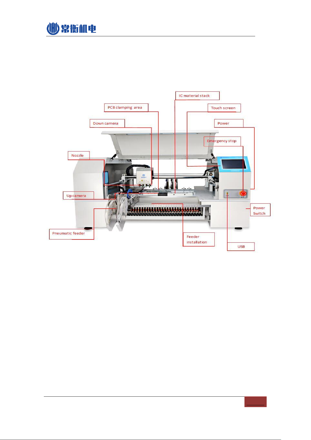
4. Machine intro
CHMT560P4 machine structure as below:
PIC4-1
(1) Nozzles: 4 heads with Juki nozzle
(2) Down-looking camera: help positioning and for mark point calibration.
(3) PCB clamping area: push the PCB on the end of left corner
(4) Bulk IC material stack: put some loose-packed ICs
(5) Full Touch screen: Touch pen or external USB mouse supported
(6) Power: 220v or 110v, fuse inside it
(7) Emergency button: press it will emergency stop, rotate to right it will pop out and
back to normal working
(8) Power switch: turn ON/OFF machine
(9) USB: connect external USB flash
(10) Up-looking camera: use for component positioning and angle calibration
(11) Feeder installation area

6
(12) Pneumatic Feeder: standard Yamaha feeder 8mm,12mm,16mm,24mm or Tube
feeder.
7
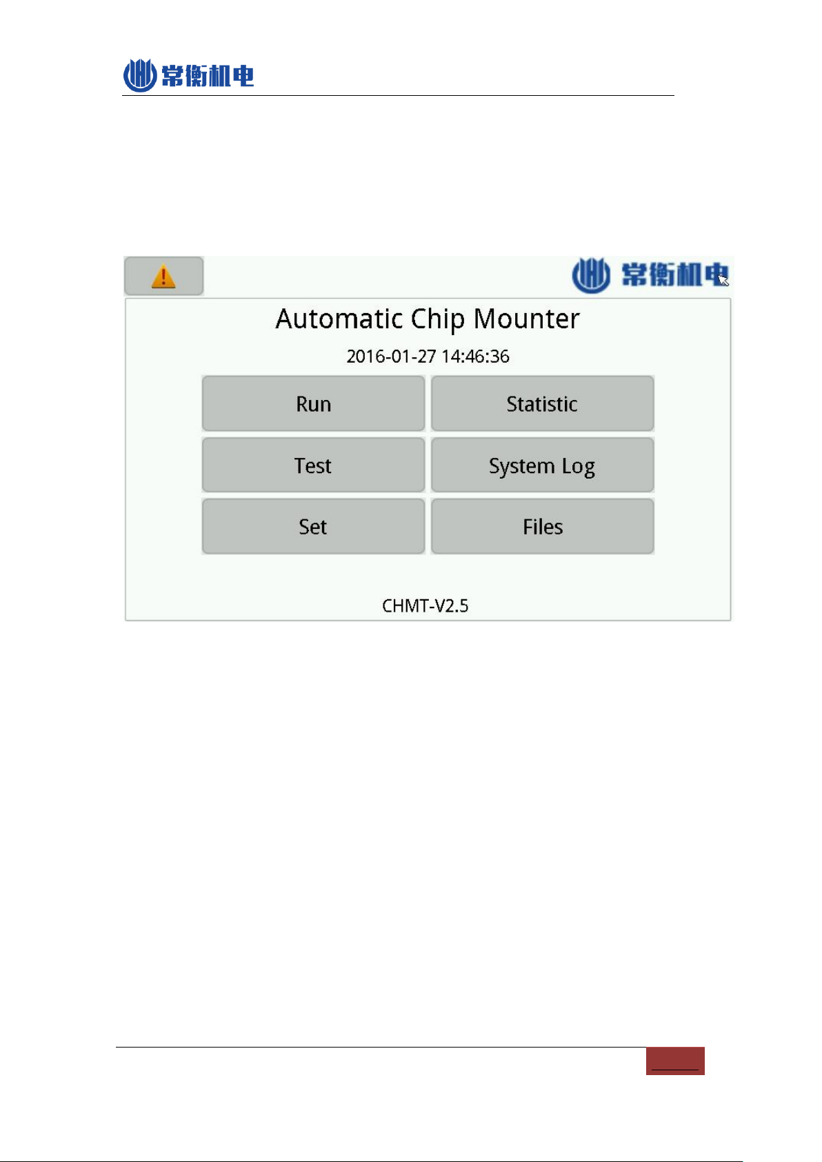
5. Start
Power on, press "confirm" on the screen, machine self-check and operation system
start, below is home page. You can normal use it now.
PIC5-1
(1) Alarm: on the left-side up triangle corner, used to check alarm detail and history.
(2) Run: Used to manage and run the working file.
(3) Test: Used to test the machine’s functions (can't amend any value, just for testing)
(4) Set: For machine settings and system set
(5) Statistic: Used to view statistics
(6) System log: For the record information
(7) Files: used to manage files and convert work file
8
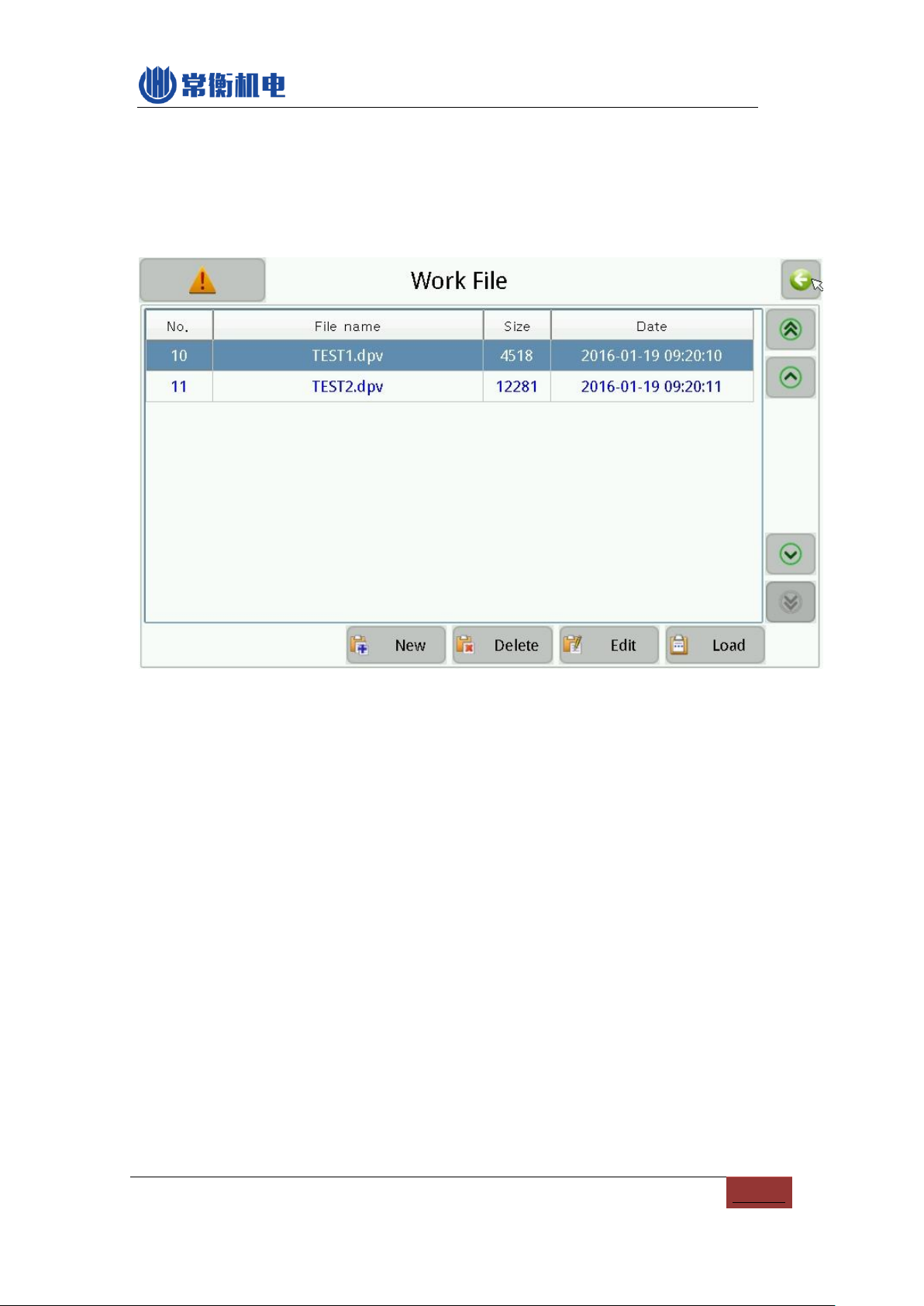
6. RUN
Home page --- Run, then you will see below image:
PIC6-1
(1) Work file: current working file
(2) New: create a new working file by yourself
(3) Delete: delete work file
(4) Edit: Edit the selected working file
(5) Load: loading the selected working file and ready to run
(6) Back: on the right-side up corner of the screen, used to back to last page.
6.1. Edit work file
Below image is edit work file:
9
PIC6-2
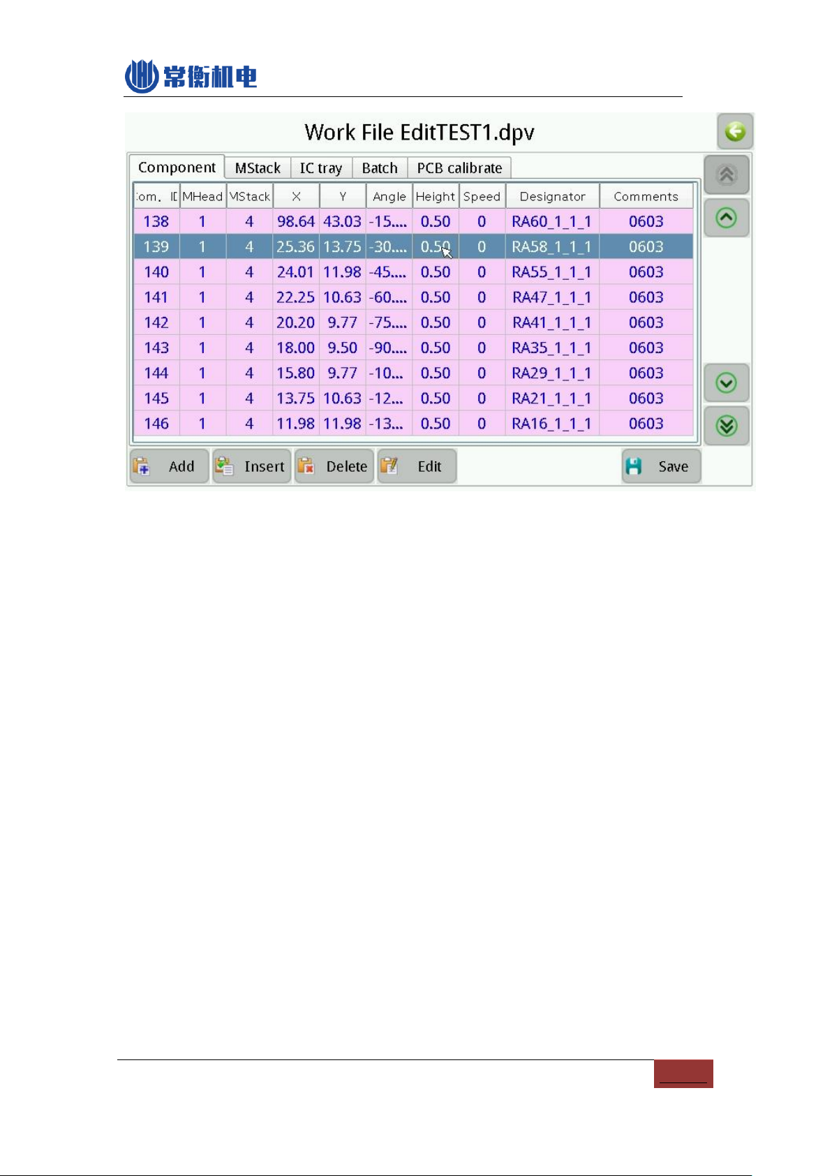
6.1.1.Component edit
As above picture:
(1) Component list
(2) Add : add a new component on the end of the sheet
(3) Insert: insert a new component before current component.
(4) Delete: delete a component
(5) Edit: edit the selected component
(6) Save: after amend the component list you need to save, if not save in time, the
save button will twinkle, then press the button and save, the twinkle end.
6.1.1.1. Edit Component
Below image:

10
PIC6-3
(1) Component number: on the left-side up corner (start from No.0). Press it you
can select the component number.
(2) Comp. ID: unique number, it won’t have 2 same comp. ID in one work file.
M Stack: stack 1-30, 31-60 is normal feeder on the two sides of machine, stack
81-91 is for front bulk IC, stack 92-100 is for vibration feeder, stack 101-119 is for
IC tray.
(3) Speed: 0 is default value, it stands for max speed(100). (For placing IC, you can
lower down the speed to 20-50, it will be more accuracy.
(4) Height: it is used for component height setting. 0.5 is default value, for under
3mm height component. More smaller value, means the component height will
more lower, means the Z axis goes more down. For higher component, you need
to set higher value. (Note: machine general height is 0.5mm, the general PCB
thickness is 1.6mm, you can adjust the height according to the thickness
of your PCB)
(5) Angle: for rotate angle of component.
(6) Designator: component identification information, such as R1, R2, C1, U1 etc.
(7) Comments: component information, such as 0402, 0805 etc.
(8) M Head: nozzle for this component
(9) Coordinate X: usually work file generated from software no need to change the

11
setting. (If you create file manually, then you can press to adjust
the position.)
(10) Coordinate Y: usually work file generated from software no need to change the
setting.(If you create file manually, then you can press to adjust
the position.)
(11) Skip comp: means not place this component
(12) No throwing inspection: means forbid throwing materials due to lack of
vacuum. (Note: 1. If you have enable "use vision" function, then this function can
be OFF.)
(13) Use vision: means open camera vision system, if turn off, the speed will
increase but accuracy will be lower.
(14) Coord. Set: After press the cross, machine head moving to the component
position, and you can move the arrow to set the component position seeing from
down-looking camera (when you are creating work file manually in machine).
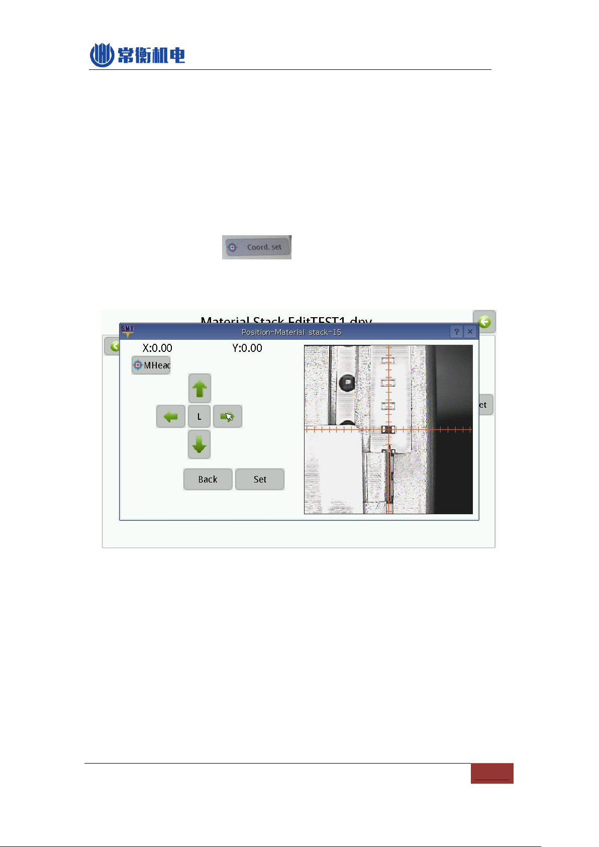
6.1.1.2. Coordinate set

12
PIC6-4
(1) Coordinate: X and Y’s coordinate is relative coordinates, means the coordinate
after movement comparing with previous coordinate.
(2) Vision: press this button exchange nozzle positioning and vision positioning, we
suggest use vision positioning, nozzle position not that accurate.
(3) Two point: means diagonal positioning, left-up corner and right-down corner. We
suggest use this function for some big ICs, pictures as below:
Left-up corner right-down corner
Note: use this way of positioning, don’t view printing silk frame, silk printing not
accurate, you need to view the bonding pad.
(4) Move: “L” for low speed, “H” for high speed.
(5) Set: press it for save position changes
6.1.2.Material Stack Edit

13
PIC6-5
(1) M Stack list
(2) Add: add a new stack at the end of stack list;
(3) Insert: insert a new stack
(4) Delete: delete the selected stack, note: If delete this stack, the components will
be delete as well.
(5) Edit: edit selected stack, image as below:
PIC6-6
a) Stack ID: 1-30 /31-60 for normal feeder, 81-91 for front bulk IC material, 101-119
user defined IC tray, If edit the stack ID, all the component will be changed as
well.
b) X/Y offset: Default value is 0, after adjust the picking position, it will be changed.
c) Take Height: means picking height, the component in the reel if too high, you
can set the take height.
d) Take delay: it means the picking head stopping time on the component. (It is for
heavy component and ICs)
e) EC height: means component height, normal component height is 3mm, when
you have higher component, then set this value higher.
f) Speed: means the Z axis up and down speed, 0 stands for max speed(100). For
14
ICs, please slow down the speed.
g) Head: machine's head
h) Angle compensation: you can set this to adjust the offset of angle.
i) Comments: component information(for your own recognize)
j) EC size X/Y: Aid function for camera vision calibrate, please keep it 0.
k) Skip comp. Not place this component, same as above mentioned.
l) No throwing inspection: function the same as “component edit” as above.
m) Use vision: function the same as “component edit” as above.
n) Coord. set: press to select the pick position, image as below:
(For picking position, the cross must aim and pick the first component showing
on the feeder)
PIC6-7
6.1.3. IC Tray edit
IC tray stack number from 101-119, software allow max 20pcs IC tray.
IC tray fixed on the holding area, you can put anywhere on the machine's work area.
some IC out in a whole black tray with array shape, machine will pick the IC from left to
right, down to up. IC tray edit image as below:

15
PIC6-8
The stack number is from 81 -100, IC tray edit image as below:
PIC6-9
(1) First IC center coord. X/Y: on the left-down side corner;
(2) Last IC center coord. X/Y: on the right-up side corner;
(3) X/Y direction number: The number of X/Y direction on IC
(4) Start IC number: from number 0, IC number from left to right, up to down, when
running, machine will start from your selected IC number.
16
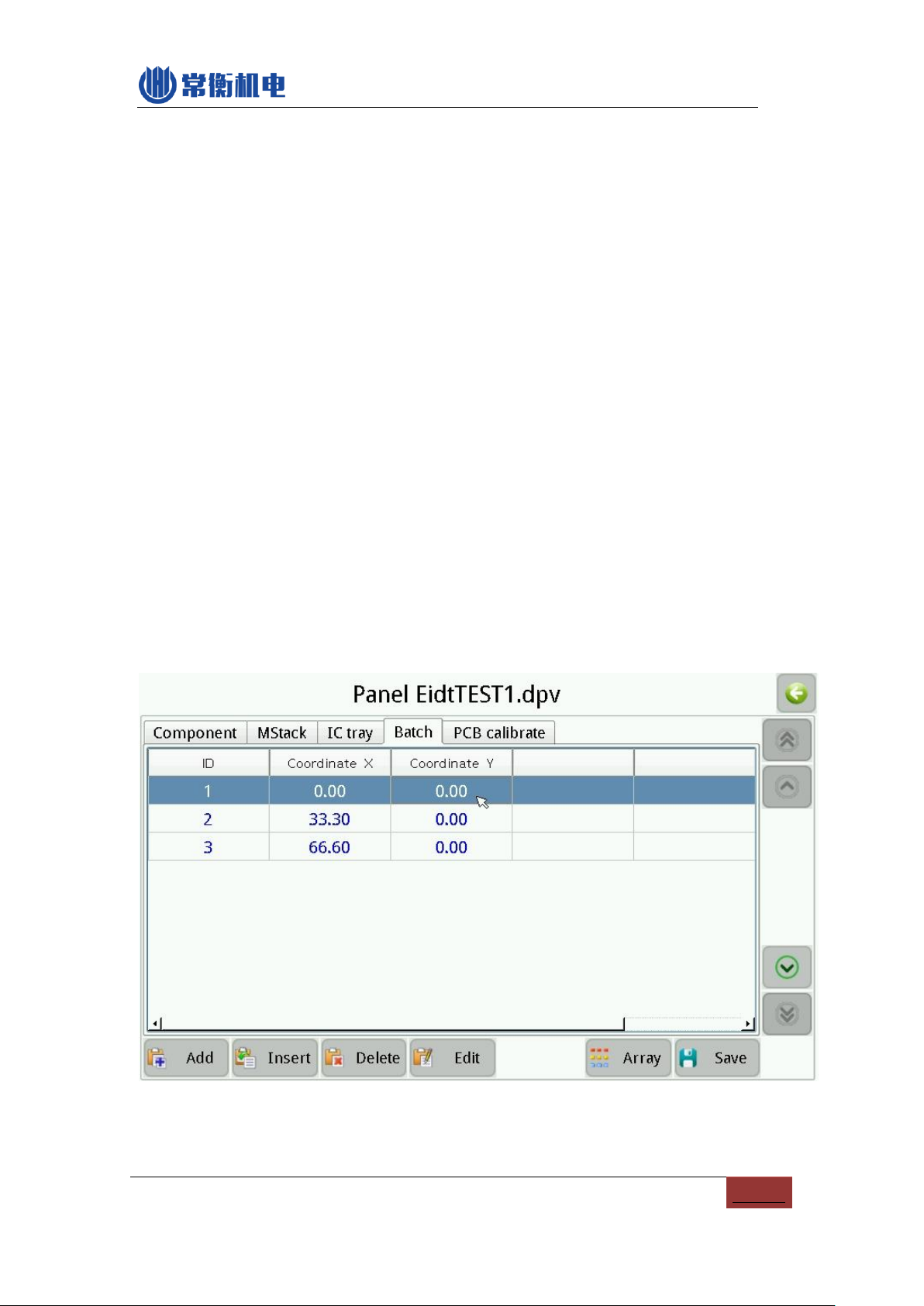
6.1.4. Batch edit
Batch is very convenient for same multi PCBs. There are 2 ways of Batch: "Coord"
or "Array" positioning for PCB. "Coord" positioning according to the origin point of each
PCB, "Coord" way is complicated but more accurate; "Array" positioning need to know
how many PCB quantity for X and Y direction. And each board's X and Y direction Spacing
(means board size, you can use a ruler to measure the size), then machine will calculate
the origin point automatically.
Reference teaching video:
Batch 1 - Array
https://www.youtube.com/watch?v=HrLop77IaJ8&feature=youtu.be
Batch 2 - coordinate
www.youtube.com/watch?v=kuQAqu-MFS4)
6.1.4.1. Coord.
Coordinate way image as below:
PIC6-10
Above picture, one line for one PCB, X and Y for origin point coordinate.

17
6.1.4.2. Array
Array way image as below:
PIC6-11
“Add skip”, it can skip some PCB and not mounting this PCB.
“Create single” used to all the small PCB expand to one PCB, and save into a new work
file. This function means you can adjust one single component in this new PCB. New work
file will show “Single” at end for the name.
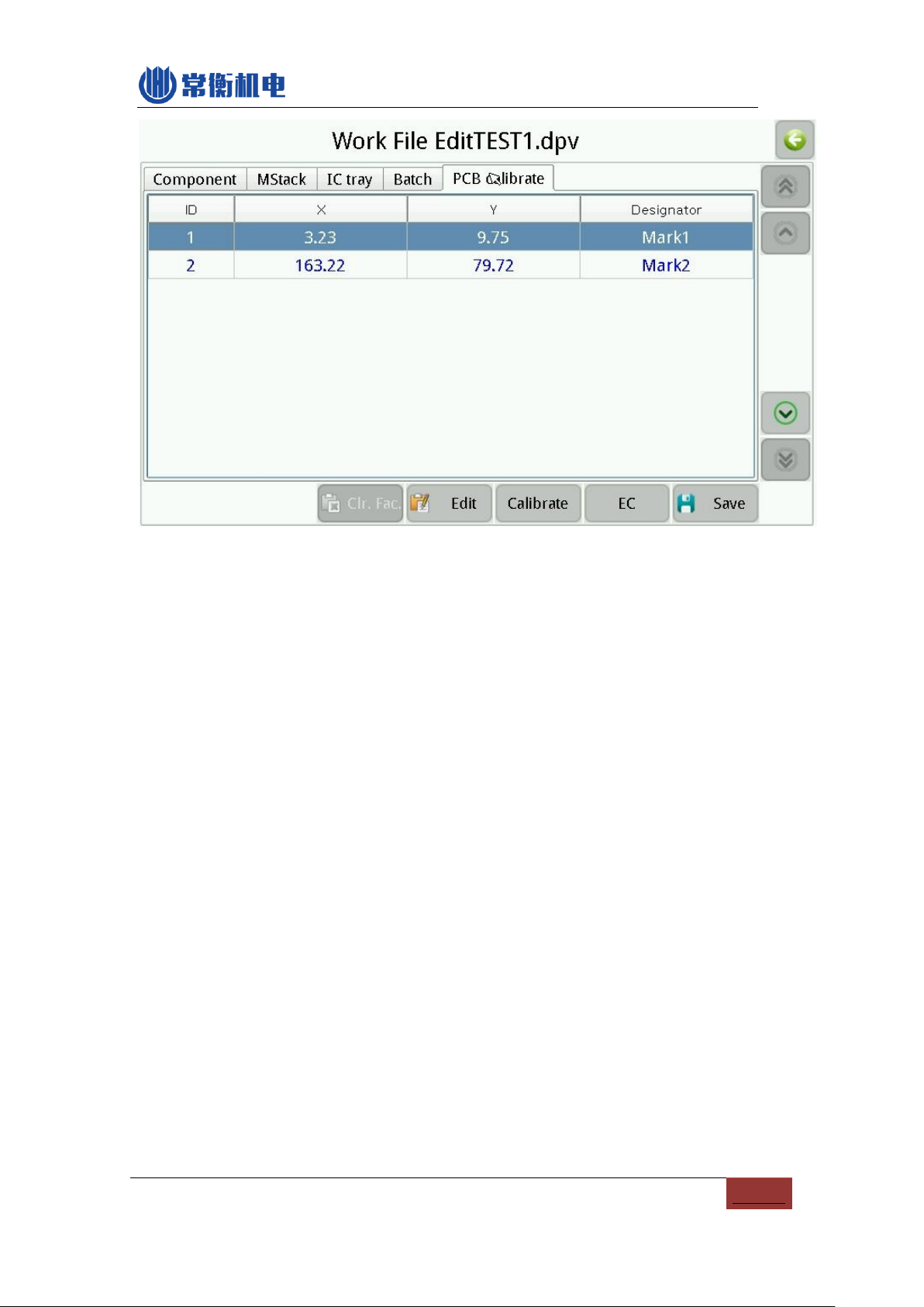
6.1.5.PCB calibrate
Due to each PCB is different, it has some offset when placing the second board, in
order to ensure the accuracy, you need to calibrate the actual position of the PCB and
component. Machine will auto find 2 components position of PCB, more smaller
component, higher precision.
Image as below:
18
PIC6-12
Two ways of PCB calibrate:
Component coordinate: the left-up corner component + the right-down corner
component.
Mark point: you can use 2 random components as Mark point, or use the mark
point of this PCB directly, after positioning the two points, then all of other
components of this PCB will be correction automatically. (Note: 2 mark points
need to be far apart, such as one in left-up corner and another in right-down
corner.)

19
PIC6-13
How to set Mark pointAuto Calibration CHMT 5 series models:
www.youtube.com/watch?v=HLL6ignTYyU
6.2. Run
After work file completion, now you can run this file!
Image as below:
Table of contents
Other Charmhigh Industrial Equipment manuals


