manuals.online logo
Brands
  1. Home
  2. •
  3. Brands
  4. •
  5. Mayr
  6. •
  7. Industrial Equipment
  8. •
  9. Mayr EAS-NC Lastic-Backlash-free Quick start guide

Mayr EAS-NC Lastic-Backlash-free Quick start guide

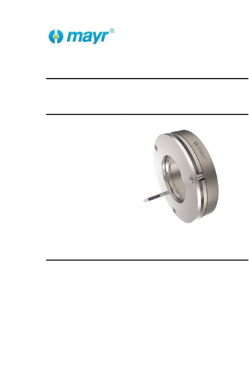
Installation and Operational Instructions for EAS®-NC
Lastic-Backlash-free clutch Type 454._ _ _._
Sizes 01 to 3 (B.4.8.3.EN)
22/04/2021 TK/MD/SU Chr. Mayr GmbH + Co. KG
Eichenstraße 1, D-87665 Mauerstetten, Germany
Phone: +49 8341 804-0, Fax: +49 8341 804-421
Page 1 of 5 www.mayr.com, E-Mail: public.m[email protected]
Please read these Operational Instructions carefully and follow them accordingly!
Ignoring these Instructions may lead to malfunctions or to clutch failure, resulting in damage to other parts.
Contents:
Page 1: - Contents
- Safety and Guideline Signs
- Safety Regulations
Page 2: - Clutch Illustrations (Variants)
- Parts List
Page 3: - State of Delivery
- Function
- Temperature Resistance
- Design
- Limit Switch
Page 4: - Clutch Installation
- Installation of Both Clutch Halves
- De-installation
- Installation of the Clutch Halves with Keyway
- Joining Both Clutch Halves
Page 5: - Permitted Shaft Misalignments
- Clutch Alignment
- Maintenance
- Disposal
- Technical Data
Safety and Guideline Signs
CAUTION
Danger of injury to personnel and
damage to machines.
Please Observe!
Guidelines on important points.
Safety Regulations
These Installation and Operational Instructions (I + O) are part of the clutch delivery.
Please keep them handy and near to the clutch at all times.
It is forbidden to start initial operation of the product until you have ensured that all applicable EU directives and directives
for the machine or system, into which the product has been installed, have been fulfilled.
At the time these Installation and Operational Instructions go to print, the EAS®-clutches accord with the known technical
specifications and are operationally safe at the time of delivery.
Without a conformity evaluation, this product is not suitable for use in areas where there is a high danger of explosion.
This statement is based on the ATEX directive.
DANGER
If the EAS®-clutches are modified.
If the relevant standards for safety and / or installation conditions are ignored.
User-implemented Protective Measures
Cover all moving parts to protect against seizure, dust impacts or foreign body impact.
The clutches may not be put into operation without a limit switch unless mayr® has been contacted and has agreed
otherwise.
To prevent injury or damage, only specialist personnel are allowed to work on the components. They must be
familiar with the dimensioning, transport, installation, initial operation, maintenance and disposal according to
the relevant standards and regulations.
Please read the Installation and Operational Instructions carefully prior to installation and initial operation of the
device.
These Safety Regulations are user hints only and may not be complete!
Installation and Operational Instructions for EAS®-NC
Lastic-Backlash-free clutch Type 454._ _ _._
Sizes 01 to 3 (B.4.8.3.EN)
22/04/2021 TK/MD/SU Chr. Mayr GmbH + Co. KG
Eichenstraße 1, D-87665 Mauerstetten, Germany
Phone: +49 8341 804-0, Fax: +49 8341 804-421
Page 2 of 5 www.mayr.com, E-Mail: public.m[email protected]
Fig. 1
Parts List (Only use mayroriginal parts)
Item
Name
1
EAS®-NC clutch
1.1
Connection flange
1.2
Cap screw
1.3
Tensioning screw - cone bushing
2
Elastomeric element (red 98 Sh A / yellow 92 Sh A)
3.1
ROBA®-ES clamping hub
3.1.1
Tensioning screw - clamping hub
3.2
ROBA®-ES shrink disk hub
3.2.1
Tensioning screw - shrink disk hub
3.3
ROBA®-ES hub with keyway
4
Limit switch
Please observe the Installation and Operational Instructions B.4.8.2.EN for the EAS®-NC clutch Item 1.
The limit switch Item 4 is not included in the standard scope of delivery.
contactless
limit switch
Installation and Operational Instructions for EAS®-NC
Lastic-Backlash-free clutch Type 454._ _ _._
Sizes 01 to 3 (B.4.8.3.EN)
22/04/2021 TK/MD/SU Chr. Mayr GmbH + Co. KG
Eichenstraße 1, D-87665 Mauerstetten, Germany
Phone: +49 8341 804-0, Fax: +49 8341 804-421
Page 3 of 5 www.mayr.com, E-Mail: public.m[email protected]
State of Delivery
The clutch (EAS®-NC part and flexible part) is completely
assembled and set to the torque stipulated in the order, if required.
Please check the state of delivery!
Function
EAS®-NC-Lastic-Backlash-free clutches are backlash-free, positive
locking, torque-limiting overload clutches in combination with a
flexible coupling for the connection of two shafts.
While compensating for axial, radial and angular misalignments, the
EAS®-NC-Lastic-Backlash-free transmits the torque reliably and
safely from the input to the output in normal operation.
In case of overload, i.e. when the set limit torque is exceeded, the
clutch separates the input and the output.
The mayr®limit switch registers the overload and transmits a signal
to switch off the drive or any other control function.
Temperature Resistance
EAS®-NC clutches Type 454. can be operated in continuous use up
to a temperature of -20 °C/ +80 °C; short-term temperature peaks of
up to +120 °C are allowed.
Designs
1. EAS®-NC-Lastic-Backlash-free Ratchetting Clutch
Type 454._ _0._
ratchets on overload and emits an electrical signal (via the limit
switch) to switch off the drive. The detent torque is substantially
lower than the set disengagement torque. Re-engagement takes
place automatically.
2. EAS®-NC-Lastic-Backlash-free Synchronous Clutch
Type 454._ _5._
emits an electrical signal (via the limit switch) on overload to switch
off the drive, releases it mechanically and re-connects the drive
elements after one turn (360°).
The residual torque in a disengaged condition is substantially lower
than the set disengagement torque.
Re-engagement takes place automatically at the same point at
which it disengaged.
Limit Switch
In case of overload, the mayr®limit switch registers the clutch
disengagement quickly and precisely and emits a signal to switch
off the drive or other control functions.
Installation and Operational Instructions for EAS®-NC
Lastic-Backlash-free clutch Type 454._ _ _._
Sizes 01 to 3 (B.4.8.3.EN)
22/04/2021 TK/MD/SU Chr. Mayr GmbH + Co. KG
Eichenstraße 1, D-87665 Mauerstetten, Germany
Phone: +49 8341 804-0, Fax: +49 8341 804-421
Page 4 of 5 www.mayr.com, E-Mail: public.m[email protected]
Clutch Installation
EAS®-NC clutches include cone bushings, shrink disks, clamping
hubs or keyways as part of the standard delivery.
The EAS®-NC clutch (1) and the ROBA®-ES-coupling hub (3) are
mounted onto the shafts and secured axially (example Fig. 2).
After this, both clutch halves can simply be pushed together.
Please Observe!
Do not put any axial pressure onto the elastomeric element (2).
The distance dimension “E” acc. Table 1 and Fig. 2 must be
observed!
Fig. 2
Installation of Both Clutch Halves
Installation of the clutch halves Type 454._0/1_._
EAS®-NC side (1) cone bushing
ROBA®-ES-side clamping hub (3.1) or shrink disk hub (3.2)
During installation, please observe the following:
The shafts must not have a keyway.
Shaft tolerances: EAS®-NC-side up to diameter 38 h6,
ROBA®-ES-side over diameter 38 h8 or k6.
Shaft surface: finely turned or ground
(Ra = 0.8 µm).
Shaft material: yield point at least 400 N/mm2,
e.g. C45 +QT, 42CrMoS4 +QT.
Degrease or remove conserving layers on the shafts and
bores before installing the clutch.
Greasy or oily bores or shafts do not transmit the torques
defined in the catalogue.
Mount both shaft ends and bring them into the correct position.
On Type 454._0_._
Tighten the tensioning screw (3.1.1) on the ROBA®-ES-side
using a torque wrench to the required torque stated in Table 1.
Tighten the tensioning screw (1.3) on the EAS®-NC-side
stepwise (in 3 to max. 6 tightening sequences) and cross-wise
evenly using a torque wrench to the required torque stated in
Table 1.
On Type 454._1_._
Tighten the tensioning screws (3.2.1) on the ROBA®-ES-side
stepwise (in 3 to max. 6 tightening sequences) and cross-wise
evenly using a torque wrench to the required torque stated in
Table 1.
Tighten the tensioning screws (1.3) on the EAS®-NC-side
stepwise (in 3 to max. 6 tightening sequences) and cross-wise
evenly using a torque wrench to the required torque stated in
Table 1.
De-installation
Loosen all tensioning screws by several thread turns.
Screw out the tensioning screws located next to the tapped
extracting holes and screw them into the tapped extracting
holes up to their limits. Then tighten these screws until the
tensioning connections loosen.
Fig. 3
Fig. 4
Installation of the Clutch Halves with Keyway
Type 454._2_._
Mount the clutch halves (1 or 3.3) onto both shaft ends using a
suitable device and bring them into the correct position.
with a press cover and a screw, screwed into the shaft
threaded center hole and/or a locking set screw (see Fig. 2).
Joining Both Clutch Halves
Due to the pre-tension on the flexible elastomeric element (2), an
axial installation force is required when joining the clutch hubs (1
and 3._). The force required can be reduced by lightly greasing the
elastomeric element.
Attention! Use PU-compatible lubricants (e. g. Vaseline)!
Please Observe!
Do not put any axial pressure onto the elastomeric element (2).
The distance dimension “E” acc. Table 1 and Fig. 2 must be
observed!
Contact surface
Contact surface
Installation and Operational Instructions for EAS®-NC
Lastic-Backlash-free clutch Type 454._ _ _._
Sizes 01 to 3 (B.4.8.3.EN)
22/04/2021 TK/MD/SU Chr. Mayr GmbH + Co. KG
Eichenstraße 1, D-87665 Mauerstetten, Germany
Phone: +49 8341 804-0, Fax: +49 8341 804-421
Page 5 of 5 www.mayr.com, E-Mail: public.m[email protected]
Permitted Shaft Misalignments
The EAS®-NC-Lastic-Backlash-free clutch compensates for angular,
axial and radial misalignments (Fig. 5) without losing its backlash-
free function. However, the permitted shaft misalignments stated in
Table 1 must not simultaneously reach their maximum value. If
more than one kind of misalignment takes place simultaneously,
they influence each other. This means that the permitted
misalignment values are dependent on one another, see Fig. 6.
The sum total of the actual misalignments in percent of the
maximum value must not exceed 100 %.
The permitted misalignment values stated in Table 1 refer to clutch
operation at nominal torque, an ambient temperature of +30 °C and
an operating speed of 1500 rpm.
If the clutch is operated in other or more extreme operating
conditions, please contact the manufacturers.
Axial Radial Angular
displacement misalignment misalignment
Fig. 5
Clutch Alignment
Exact alignment of the clutch improves the running smoothness of
the clutch substantially, reduces the load on the shaft bearings and
increases the clutch service lifetime.
We recommend alignment of the clutch using a dial gauge or
special laser on drives operating at very high speeds.
Fig. 6
Maintenance
EAS®-NC-Lastic-Backlash-free clutches are largely maintenance-
free, only extreme ambient conditions or clutch operating conditions
may lead to wear of the elastomeric element (2).
It is recommended to carry out a visual inspection within the scope
of the inspections carried out at regular intervals.
Disposal
Electronic components (Limit switch):
Products which have not been disassembled can be disposed of
under Code No. 160214 (mixed materials) or components under
Code No. 160216, or can be disposed of by a certified disposal firm.
Steel components:
Steel scrap (Code No. 160117)
All aluminum components:
Non-ferrous metals (Code No. 160118)
Seals, O-rings, V-seals, elastomers:
Plastic (Code No. 160119)
Table 1: Technical Data
EAS®-NC-Lastic-Backlash-free Size
01
0
1
2
3
Distance Dimension “E” [mm]
16
18
20
24
26
Axial displacement ΔKa[mm]
1.2
1.4
1.5
1.8
2.0
Radial misalignment ΔKr92 Sh A / 98 Sh A [mm]
0.1 / 0.06
0.14 / 0.1
0.15 / 0.11
0.17 / 0.12
0.19 / 0.14
Angular misalignment α 92 Sh A / 98 Sh A [°]
1.0 / 0.9
1.0 / 0.9
1.0 / 0.9
1.0 / 0.9
1.0 / 0.9
Angular misalignment Δz 92 Sh A / 98 Sh A [mm]
0.35 / 0.31
0.39 / 0.35
0.57 / 0.51
0.70 / 0.63
0.83 / 0.75
Tightening torque
Tensioning screw - cone bushing (1.3) [Nm]
3
3
5.5
9.5
9.5
Tightening torque
Tensioning screw - clamping hub (3.1.1) [Nm]
10.5
10.5
25
25
70
Tightening torque
Tensioning screw - shrink disk (3.2.1) [Nm]
3
6
6
10.5
30
Difference dimension Δz = z1- z2
Dimensions z1and z2are measured
vertically and horizontally offset by 180°.
Δz [%]
Angular misalignment
ΔKa[%] Axial displacement
ΔKr[%] Radial misalignment

Other Mayr Industrial Equipment manuals

Mayr ROBA-servostop 8980.00 00 Quick start guide

Mayr

Mayr ROBA-servostop 8980.00 00 Quick start guide

Mayr EAS-Compact 49 Series Quick start guide

Mayr

Mayr EAS-Compact 49 Series Quick start guide

Mayr ROBA-quick Quick start guide

Mayr

Mayr ROBA-quick Quick start guide

Mayr ROBA-stop-stage Owner's manual

Mayr

Mayr ROBA-stop-stage Owner's manual

Mayr EAS-NC Quick start guide

Mayr

Mayr EAS-NC Quick start guide

Mayr ROBA-stop-S 856 Quick start guide

Mayr

Mayr ROBA-stop-S 856 Quick start guide

Mayr EAS-compact 493. 4 .0 Series User manual

Mayr

Mayr EAS-compact 493. 4 .0 Series User manual

Mayr ROBA-ES 94 Series Quick start guide

Mayr

Mayr ROBA-ES 94 Series Quick start guide

Mayr ROBA-DS 956 Series Quick start guide

Mayr

Mayr ROBA-DS 956 Series Quick start guide

Mayr EAS-HT 405 Series Quick start guide

Mayr

Mayr EAS-HT 405 Series Quick start guide

Mayr EAS-XT 475.24 Series Quick start guide

Mayr

Mayr EAS-XT 475.24 Series Quick start guide

Mayr EAS-Compact Quick start guide

Mayr

Mayr EAS-Compact Quick start guide

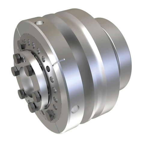
Mayr ROBATIC-clutch Quick start guide

Mayr

Mayr ROBATIC-clutch Quick start guide

Mayr ROBA-servostop 8981.29 01 Quick start guide

Mayr

Mayr ROBA-servostop 8981.29 01 Quick start guide

Mayr ROBA-takt Quick start guide

Mayr

Mayr ROBA-takt Quick start guide

Mayr EAS-dutytorque 404 400 Series Quick start guide

Mayr

Mayr EAS-dutytorque 404 400 Series Quick start guide

Mayr ROBA-stop-S User manual

Mayr

Mayr ROBA-stop-S User manual

Mayr ROBATIC 500.1 Series Quick start guide

Mayr

Mayr ROBATIC 500.1 Series Quick start guide

Mayr EAS-Sm User manual

Mayr

Mayr EAS-Sm User manual

Mayr EAS-Compact Type 49. 4. Size 4 Series Quick start guide

Mayr

Mayr EAS-Compact Type 49. 4. Size 4 Series Quick start guide

Mayr EAS 400 04.7 Series User manual

Mayr

Mayr EAS 400 04.7 Series User manual

Mayr Smartflex 932.3 3 Series Quick start guide

Mayr

Mayr Smartflex 932.3 3 Series Quick start guide

Mayr EAS-Compact 49 Series Quick start guide

Mayr

Mayr EAS-Compact 49 Series Quick start guide

Mayr ROBA -brake-checker plus User manual

Mayr

Mayr ROBA -brake-checker plus User manual

Popular Industrial Equipment manuals by other brands

ANEMOI AIRPIVOT installation manual

ANEMOI

ANEMOI AIRPIVOT installation manual

Eaton Char-Lynn HP30 instruction manual

Eaton

Eaton Char-Lynn HP30 instruction manual

Parkside PUTK 50 B1 operating instructions

Parkside

Parkside PUTK 50 B1 operating instructions

Tormach Automatic Tool Changer owner's guide

Tormach

Tormach Automatic Tool Changer owner's guide

Spectris NDC PREHEATER MCS120 Operator's guide

Spectris

Spectris NDC PREHEATER MCS120 Operator's guide

Sewosy CPREG-1 Mounting instructions

Sewosy

Sewosy CPREG-1 Mounting instructions

ABB HT609723 Operation manual

ABB

ABB HT609723 Operation manual

Siemens SIRIUS 3RA1913-1 Series operating instructions

Siemens

Siemens SIRIUS 3RA1913-1 Series operating instructions

Stepp SRM Operation, maintenance and parts manual

Stepp

Stepp SRM Operation, maintenance and parts manual

Esko Kongsberg XN Site Preparation

Esko

Esko Kongsberg XN Site Preparation

Holzstar DB 900 operating instructions

Holzstar

Holzstar DB 900 operating instructions

Pack Leader PL-622 Operational manual

Pack Leader

Pack Leader PL-622 Operational manual

ABB HT846641 Operation manual

ABB

ABB HT846641 Operation manual

Viessmann Vitogate 300 Nstallation and service instructions

Viessmann

Viessmann Vitogate 300 Nstallation and service instructions

SUHNER ABRASIVE LVC 20 Technical document

SUHNER ABRASIVE

SUHNER ABRASIVE LVC 20 Technical document

Afag SE20 Assembly and operating instructions

Afag

Afag SE20 Assembly and operating instructions

MIR 250 user guide

MIR

MIR 250 user guide

Jäger Z62-M260.23 S5 manual

Jäger

Jäger Z62-M260.23 S5 manual

manuals.online logo
manuals.online logoBrands
  • About & Mission
  • Contact us
  • Privacy Policy
  • Terms and Conditions

Copyright 2025 Manuals.Online. All Rights Reserved.