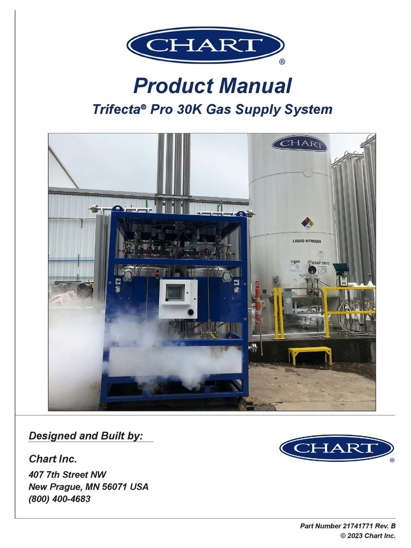
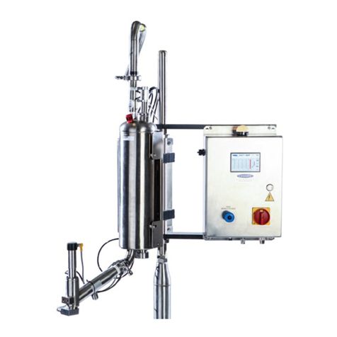
CHART Trifecta Pro Series User manual

Part Number 21486938 Rev. A
© 2019 Chart Inc.
Designed and Built by:
Chart Inc.
407 7th Street NW
New Prague, MN 56071 USA
(800) 400-4683
Product Manual
Trifecta
Pro Series


iii
Product Manual - Trifecta®Pro Series
Contents
Revision Log . . . . . . . . . . . . . . . . . . . . . . . . . . . . . . . . . . . . . . . . . . . . . . iv
Preface . . . . . . . . . . . . . . . . . . . . . . . . . . . . . . . . . . . . . . . . . . . . . . . . . . . . .1
General . . . . . . . . . . . . . . . . . . . . . . . . . . . . . . . . . . . . . . . . . . . . . . . . . .1
Product Highlights. . . . . . . . . . . . . . . . . . . . . . . . . . . . . . . . . . . . . . . . . . . . .1
Product Manual . . . . . . . . . . . . . . . . . . . . . . . . . . . . . . . . . . . . . . . . . . . . . .1
Terms . . . . . . . . . . . . . . . . . . . . . . . . . . . . . . . . . . . . . . . . . . . . . . . . . . .2
Acronyms / Abbreviations. . . . . . . . . . . . . . . . . . . . . . . . . . . . . . . . . . . . . . . . .2
Introduction . . . . . . . . . . . . . . . . . . . . . . . . . . . . . . . . . . . . . . . . . . . . . . . . . .3
General . . . . . . . . . . . . . . . . . . . . . . . . . . . . . . . . . . . . . . . . . . . . . . . . . .3
Typical Layout. . . . . . . . . . . . . . . . . . . . . . . . . . . . . . . . . . . . . . . . . . . . . . .3
Flow Capacity . . . . . . . . . . . . . . . . . . . . . . . . . . . . . . . . . . . . . . . . . . . . . . .3
Safety . . . . . . . . . . . . . . . . . . . . . . . . . . . . . . . . . . . . . . . . . . . . . . . . . . . . .5
General . . . . . . . . . . . . . . . . . . . . . . . . . . . . . . . . . . . . . . . . . . . . . . . . . .5
Safety Summary . . . . . . . . . . . . . . . . . . . . . . . . . . . . . . . . . . . . . . . . . . . . . .5
Safety Bulletin. . . . . . . . . . . . . . . . . . . . . . . . . . . . . . . . . . . . . . . . . . . . . . .6
. . . . . . . . . . . . . . . . . . . . . . . . . . . . . . . . . . . . . .6
Oxygen Enriched Atmospheres . . . . . . . . . . . . . . . . . . . . . . . . . . . . . . . . . . . . . .7
Nitrogen and Argon . . . . . . . . . . . . . . . . . . . . . . . . . . . . . . . . . . . . . . . . . . . .7
Installation. . . . . . . . . . . . . . . . . . . . . . . . . . . . . . . . . . . . . . . . . . . . . . . . . . .9
Installation Procedure . . . . . . . . . . . . . . . . . . . . . . . . . . . . . . . . . . . . . . . . . . .9
Placement of Trifecta Pro Series Skid. . . . . . . . . . . . . . . . . . . . . . . . . . . . . . . . . . .9
Liquid Line Piping to Bulk Tank . . . . . . . . . . . . . . . . . . . . . . . . . . . . . . . . . . . . .9
Piping to Vaporizer . . . . . . . . . . . . . . . . . . . . . . . . . . . . . . . . . . . . . . . . . . . 10
Bulk Tank Pressure Transmitter . . . . . . . . . . . . . . . . . . . . . . . . . . . . . . . . . . . . .11
Electrical Power Supply . . . . . . . . . . . . . . . . . . . . . . . . . . . . . . . . . . . . . . . . .11
Commissioning . . . . . . . . . . . . . . . . . . . . . . . . . . . . . . . . . . . . . . . . . . . . . 11
Purge and Pre-Charge of the Trifecta XPro Series . . . . . . . . . . . . . . . . . . . . . . . . . 11
Check Trifecta Pro Series Cylinder Relief Valves . . . . . . . . . . . . . . . . . . . . . . . . . 15
Operation . . . . . . . . . . . . . . . . . . . . . . . . . . . . . . . . . . . . . . . . . . . . . . . . . . 17
Hard Sets (Complete Parameter List) . . . . . . . . . . . . . . . . . . . . . . . . . . . . . . . . . . 17
HMI Screens. . . . . . . . . . . . . . . . . . . . . . . . . . . . . . . . . . . . . . . . . . . . . . .18
MAIN Screen . . . . . . . . . . . . . . . . . . . . . . . . . . . . . . . . . . . . . . . . . . . .18
HIGH/HIGH HIGH ALARM Screen. . . . . . . . . . . . . . . . . . . . . . . . . . . . . . . .18
ALERT Screen . . . . . . . . . . . . . . . . . . . . . . . . . . . . . . . . . . . . . . . . . . . 18
ALARM Screen . . . . . . . . . . . . . . . . . . . . . . . . . . . . . . . . . . . . . . . . . . 19
ALARM & ALERT HISTORY Screen . . . . . . . . . . . . . . . . . . . . . . . . . . . . . . .19
RESET COUNTS Popup . . . . . . . . . . . . . . . . . . . . . . . . . . . . . . . . . . . . . .19
SETPOINT DATA ENTRY Popup . . . . . . . . . . . . . . . . . . . . . . . . . . . . . . . . . 20
INFO Popup . . . . . . . . . . . . . . . . . . . . . . . . . . . . . . . . . . . . . . . . . . . . 20
SCREEN MENU NAVIGATION Popup . . . . . . . . . . . . . . . . . . . . . . . . . . . . . .20
ACTIVE SETPOINT Screen . . . . . . . . . . . . . . . . . . . . . . . . . . . . . . . . . . . .20
TREND Screen . . . . . . . . . . . . . . . . . . . . . . . . . . . . . . . . . . . . . . . . . . . 21
MANUAL CONTROL Screen . . . . . . . . . . . . . . . . . . . . . . . . . . . . . . . . . . . 21
Parameter Settings. . . . . . . . . . . . . . . . . . . . . . . . . . . . . . . . . . . . . . . . . . . .21
Fill Setpoint. . . . . . . . . . . . . . . . . . . . . . . . . . . . . . . . . . . . . . . . . . . . .21
Pressure Build Setpoint. . . . . . . . . . . . . . . . . . . . . . . . . . . . . . . . . . . . . . .22
Bulk Critical Setpoint. . . . . . . . . . . . . . . . . . . . . . . . . . . . . . . . . . . . . . . .22
Operation Details . . . . . . . . . . . . . . . . . . . . . . . . . . . . . . . . . . . . . . . . . . . . 23
Mode “0” . . . . . . . . . . . . . . . . . . . . . . . . . . . . . . . . . . . . . . . . . . . . . . 24
Mode Switch “0” to “1” . . . . . . . . . . . . . . . . . . . . . . . . . . . . . . . . . . . . . . 29
Mode “1” . . . . . . . . . . . . . . . . . . . . . . . . . . . . . . . . . . . . . . . . . . . . . . 30
Mode Switch “1” to “2” . . . . . . . . . . . . . . . . . . . . . . . . . . . . . . . . . . . . . . 31

iv
Table of Contents Product Manual - Trifecta®Pro Series
Mode “2” . . . . . . . . . . . . . . . . . . . . . . . . . . . . . . . . . . . . . . . . . . . . . . 32
Mode Switch “2” to “3” . . . . . . . . . . . . . . . . . . . . . . . . . . . . . . . . . . . . . . 34
Assist Mode “3” . . . . . . . . . . . . . . . . . . . . . . . . . . . . . . . . . . . . . . . . . . 35
Mode Switch “3” to “2” . . . . . . . . . . . . . . . . . . . . . . . . . . . . . . . . . . . . . . 36
Mode Switch “3” to “0” . . . . . . . . . . . . . . . . . . . . . . . . . . . . . . . . . . . . . . 37
Service . . . . . . . . . . . . . . . . . . . . . . . . . . . . . . . . . . . . . . . . . . . . . . . . . . . . 41
Alerts & Alarms . . . . . . . . . . . . . . . . . . . . . . . . . . . . . . . . . . . . . . . . . . . . .41
Manually Operating the Valves . . . . . . . . . . . . . . . . . . . . . . . . . . . . . . . . . . . . . 41
Control Box . . . . . . . . . . . . . . . . . . . . . . . . . . . . . . . . . . . . . . . . . . . . . . . 42
Circuit Breakers . . . . . . . . . . . . . . . . . . . . . . . . . . . . . . . . . . . . . . . . . . . . . 43
Repairs. . . . . . . . . . . . . . . . . . . . . . . . . . . . . . . . . . . . . . . . . . . . . . . . . .44
Check Valve Leaking . . . . . . . . . . . . . . . . . . . . . . . . . . . . . . . . . . . . . . . . . . 44
Solenoids . . . . . . . . . . . . . . . . . . . . . . . . . . . . . . . . . . . . . . . . . . . . . . . . 44
Non-Energizing Solenoid. . . . . . . . . . . . . . . . . . . . . . . . . . . . . . . . . . . . . .44
Contaminants on Solenoid Seat . . . . . . . . . . . . . . . . . . . . . . . . . . . . . . . . . . 44
Moisture in Solenoid . . . . . . . . . . . . . . . . . . . . . . . . . . . . . . . . . . . . . . . . 44
Solenoid Failure . . . . . . . . . . . . . . . . . . . . . . . . . . . . . . . . . . . . . . . . . . 44
Leaking Components . . . . . . . . . . . . . . . . . . . . . . . . . . . . . . . . . . . . . . . . . . 44
Pressure and Liquid Level Transmitters. . . . . . . . . . . . . . . . . . . . . . . . . . . . . . . . .45
Ball Valve Maintenance and Repair . . . . . . . . . . . . . . . . . . . . . . . . . . . . . . . . . . .45
Electrical Schematic. . . . . . . . . . . . . . . . . . . . . . . . . . . . . . . . . . . . . . . . . . .46
Rail Assemblies . . . . . . . . . . . . . . . . . . . . . . . . . . . . . . . . . . . . . . . . . . . . . 48
Preventive Maintenance . . . . . . . . . . . . . . . . . . . . . . . . . . . . . . . . . . . . . . . . . . 49
Procedure . . . . . . . . . . . . . . . . . . . . . . . . . . . . . . . . . . . . . . . . . . . . . . . . 49
Recommended Spare Parts . . . . . . . . . . . . . . . . . . . . . . . . . . . . . . . . . . . . . . . 50
Troubleshooting . . . . . . . . . . . . . . . . . . . . . . . . . . . . . . . . . . . . . . . . . . . . . . .55
. . . . . . . . . . . . . . . . . . . . . . . . . . . . . . . . . . . . . . . . .55
Normal Activation of Solenoids . . . . . . . . . . . . . . . . . . . . . . . . . . . . . . . . . . . . . . . . . 55
Frost Formation . . . . . . . . . . . . . . . . . . . . . . . . . . . . . . . . . . . . . . . . . . . . . 55
Leak Check . . . . . . . . . . . . . . . . . . . . . . . . . . . . . . . . . . . . . . . . . . . . . . . 55
Data from Main Screen and Analog Pressure Gauges . . . . . . . . . . . . . . . . . . . . . . . . . 55
Appendix 1 . . . . . . . . . . . . . . . . . . . . . . . . . . . . . . . . . . . . . . . . . . . . . . . . . 57
Introduction . . . . . . . . . . . . . . . . . . . . . . . . . . . . . . . . . . . . . . . . . . . . . . . 57
HMI Screens. . . . . . . . . . . . . . . . . . . . . . . . . . . . . . . . . . . . . . . . . . . . . . .57
MAIN Screen - Master/Slave. . . . . . . . . . . . . . . . . . . . . . . . . . . . . . . . . . . .57
SETPOINT DATA ENTRY - Master/Slave . . . . . . . . . . . . . . . . . . . . . . . . . . . . 57
ACTIVE SETPOINT - Master/Slave. . . . . . . . . . . . . . . . . . . . . . . . . . . . . . . .58
. . . . . . . . . . . . . . . . . . . . . . . . . . . . . 58
Revision Log
Revision Level Date Description
A 09/17/2019 Manual Creation

1
Product Manual - Trifecta®Pro Series
General
The Trifecta Pro Series is the preferred solution for reliable
and continuous laser assist gases for delivery pressures up
liquid pressure by alternately feeding two liquid cylinders
equipped with innovative multi-function pressure building
vaporizers. The Trifecta solution utilizes a standard bulk
tanks.
Product Highlights
• System utilizes standard medium-pressure bulk tank to
lower investment and use existing assets
•
• Cylinders switch by pressure instead of level to further
reduce product loss and protect against pressure decay
• Robust design features streamlined all stainless steel
electronic control system (PLC) for increased durability
and reliability.
•
up and continuous operation.
• Frame assembly features a protective top cover in a
compact footprint with an elevated base for improved
ventilation.
•
(500 & 600 MAWP) service
• Inconel and copper material used where required on high
pressure oxygen unit
Product Manual
The Trifecta Pro Series Product Manual is designed to be
used in conjunction with all Trifecta models provided by
Chart. If there are any questions regarding the operation of
1-800-400-4683.
This manual contains information regarding the safe
oxygen with this system. It should be thoroughly read and
understood by anyone that operates the equipment.
The safety requirements for operating the system and
handling or transporting extremely cold liquid products are
shown in the Safety section. Use this safety section as a
“Safety Checklist” each time the equipment is being used.
The Introduction section discusses the general features of the
In the Installation section information is available on the best
commissioning of the system.
For information on settings and operation of the system refer
to the Operations section.
sections of this manual should aid in answering common
questions about the system. Part numbers are also available
for ease of ordering through www.chartparts.com.
Preface

2
Preface Product Manual - Trifecta®Pro Series
Terms
Throughout this manual safety precautions will be designated
as follows:
Warning! Description of a condition that
can result in personal injury or
death.
Caution! Description of a condition that
can result in equipment or
component damage.
Note: A statement that contains information
that is important enough to emphasize or
repeat.
Acronyms / Abbreviations
The following acronyms / abbreviations are used throughout
this manual:
BAR Pressure (Metric)
CGA Compressed Gas Association
MAOP Maximum Allowable Operating Pressure
MAWP Maximum Allowable Working Pressure
MPT Male Pipe Thread
NFPA National Fire Protection Association
PB Pressure Builder
PLC Programmable Logic Controller
PN Part Number
PSI Pounds per Square Inch
PSIG Pounds per Square Inch (Gauge)
SCFH Standard Cubic Feet Hour

3
Product Manual - Trifecta®Pro Series
General
Pro Series high-pressure gas supply system.
Chart works closely with our customers to ensure the total
highest performance at the lowest operating cost - all while
management.
Typical Layout
There are three main components to the "Trifecta" system:
• Medium Pressure Bulk Tank (Minimum 175 psig)
• Vaporizer(s)
• Trifecta Pro Series Skid
The Trifecta Pro Series has been designed for ease of
installation and operation. An ideal install has the Trifecta
Pro Series skid close to the liquid use valve on the bulk
vaporizer facing the sun ("heat of the day").
A typical layout is shown here:
Flow Capacity
The Trifecta Pro Series system is designed to supply high
to maintain supply pressure at or above the required pressure
setting. The unique design has self-contained diagnostics that
the Trifecta.
The Pro Series can supply liquid nitrogen and liquid argon in
maximum allowable working pressures from 500 to 600 psi.
It can supply liquid oxygen in maximum allowable working
pressures of 500 psi.
Service MAWP*
(psig)
MAOP*
(psig)
LIN
500 450
600 550
LAR
500 450
600 550
LOX 500 450
*MAWP = Maximum Allowable Working Pressure
MAOP = Maximum Allowable Operating Pressure
The system uses ambient vaporizers to maintain pressure
is dependent on the weather conditions. The best ambient
above the freezing point.
The Pro Series was developed and tested by Chart's New
Minnesota winter conditions for optimal performance in the
For example: the Trifecta X15 is rated to deliver liquid
similar to Minnesota. If the end user can tolerate lower
be set to higher pressures.
Note:
for continuous duties in excess of 8-10
hours per day. Higher duty cycles require
auxiliary pressure build capacity and
properly sized process vaporizers.
Introduction

4
Introduction Product Manual - Trifecta®Pro Series
system to:
• Build pressure in the transfer tanks using gravity and
ambient coils.
–
building coils.
–
require de-icing of the pressure building system or the
addition of higher capacity vaporizers.
•
the use point.
–The vaporizer must be sized for the geographical
–
coils will reduce the performance.
•
prior to the primary tank emptying.
–
–Special care must be given in selection of the bulk
tank that supplies the Trifecta.
–The tanks heat leak performance is critical in
transferring cryogen in the liquid state to the Trifecta.
–Liquid use lines and valves out of the bulk tank must
be sized properly. Small restrictive liquid lines and
–The pressure building system of the bulk tank
needs to be sized to build tank sub-cool. The sub-
cool condition (pressure above the liquid saturation
the liquid state as it travels to the Trifecta.
–Liquid feed lines from the bulk tank to the Trifecta
losses. Take great care in laying out your Trifecta
system. Insulating the liquid feed line will reduce its
reduced losses.

5
Product Manual - Trifecta®Pro Series
General
All operators should have a full and complete understanding
of the content of this manual before operating the equipment
described. This manual is intended to describe the operation
of the equipment and not intended to supersede any site-
any non-insulated piping can get extremely cold and should
not be touched by exposed skin. If the system requires
up.
transmitters can monitor the system pressure and liquid
levels.
that the manual isolation valve to the bulk tank be closed.
Safety Summary
Strict compliance with proper safety and handling practices
is necessary when using a cryogenic system. We recommend
that all our customers re-emphasize safety and safe handling
practices to all their employees and customers.
While every possible safety feature has been designed into
that the user of the cryogenic system carefully read to fully
understand all WARNINGS and CAUTION notes listed in
this safety summary and enumerated below.
Also read the information provided in the Safety Bulletin
for Oxygen and Inert Gases following this Safety Summary.
Periodic review of the Safety Summary is recommended.
Warning! In oxygen enriched atmospheres
ammable items burn
vigorously and could explode.
Warning! Do not permit smoking or open
ame in any area where oxygen
is stored, handled, or used.
Failure to comply with this
warning may result in serious
personal injury.
Excess accumulation of oxygen creates an oxygen-enriched
as an oxygen concentration above 23%). Certain items
considered non-combustible in air may burn rapidly in
such an environment. Keep all organic materials and other
Caution! Before removing any parts or
loosening ttings, empty the
cryogenic container of liquid
contents and release any vapor
pressure in a safe manner.
and may cause painful burns to personnel unless properly
protected. Personnel must wear protective gloves and eye
Failure to do so may result in personal injury due to the
extreme cold and pressure in the tank.
Warning! Accidental contact of liquid
gases with skin or eyes may
cause a freezing injury similar to
a burn.
Handle liquid so that it will not splash or spill. Protect your
eyes and cover skin where the possibility of contact with
goggles or a face shield should be worn if liquid ejection
or splashing may occur or cold gas may issue forcefully
removed and long sleeves are recommended for arm
shed spilled liquid.
Warning! Use only replacement parts
that are compatible with liquid
oxygen and have been cleaned
for oxygen use.
previously used in a compressed air environment. And do not
use oxygen equipment for compressed air. Failure to comply
with these instructions may result in serious damage to the
container.
Safety

6
Safety Product Manual - Trifecta®Pro Series
Caution! Before locating oxygen
equipment, become familiar
with the relevant National Fire
Protection Association (NFPA)
standards for “Bulk Oxygen
Systems at Customer Sites,”
and with all local safety codes.
The NFPA standard (www.nfpa.org) covers general
principles recommended for installing bulk oxygen systems
on industrial and institutional consumer premises.
Caution! To prevent possible tip over, do
not leave tank standing upright
unless it is secured to its
foundation (bolted down).
Transporting and erection of the tank should be performed in
accordance with rigging instructions available from Chart.
Failure to comply with these instructions may result in
serious damage to the container.
Safety Bulletin
Portions of the following information is extracted from
cryogenics is available from the CGA at www.cganet.com.
to time subjected to assorted environmental conditions of
an unforeseen nature. This safety bulletin is intended to call
attention to the fact that whenever a cryogenic container
is involved in any incident whereby the container or its
followed. The same holds true whenever the integrity or
function of a container is suspected of abnormal operation.
Good safety practices dictate the contents of a damaged or
suspect container be carefully emptied as soon as possible.
Under no circumstances should a damaged container be left
Incidents which require that such practices be followed
safety practices must be followed.
In the event of known or suspected container vacuum
problems (even if an extraordinary circumstance such as
unit. Continued use of a cryogenic container that has a
vacuum problem can lead to embrittlement and cracking.
unit is exposed to inordinate stress conditions caused by an
internal liquid leak.
recommended that any damaged container be returned to
The remainder of this safety bulletin addresses those adverse
environments that may be encountered when a cryogenic
container has been severely damaged. These are oxygen
exposure to inert gases.
Oxygen Decient Atmospheres
Warning! Nitrogen and argon vapors in
air may dilute the concentration
of oxygen necessary to support
or sustain life. Exposure to
such an oxygen decient
atmosphere can lead to
unconsciousness and serious
injury, including death.
The normal oxygen content of air is approximately 21%.
users should exercise suitable precautions.
One aspect of this possible hazard is the response of humans
when exposed to an atmosphere containing only 8 to 12%
immediate with virtually no warning.
When the oxygen content of air is reduced to about 15
an individual breathing the air is mentally incapable of
diagnosing the situation because the onset of symptoms
errors in judgment and confusion can be masked by a state of
and well being.
7
SafetyProduct Manual - Trifecta®Pro Series
Human exposure to an atmosphere containing 12% or less
oxygen leads to rapid unconsciousness. Unconsciousness can
occur so rapidly that the user is rendered essentially helpless.
This can occur if the condition is reached by an immediate
oxygen.
atmospheres rely on the “buddy system” for protection -
obviously the “buddy” is equally susceptible to asphyxiation
if he or she enters the area to assist the unconscious partner
unless equipped with a portable air supply. Best protection
is obtainable by equipping all individuals with a portable
supply of respirable air. Life lines are acceptable only if the
area is essentially free of obstructions and individuals can
assist one another without constraint.
exist:
1. Use the “buddy system.” Use more than one “buddy” if
necessary to move a fellow worker in an emergency.
2. Both the worker and “buddy” should be equipped with
self-contained or airline breathing equipment.
Oxygen Enriched Atmospheres
An oxygen-enriched atmosphere occurs whenever the normal
oxygen content of air is allowed to rise above 23%. While
can occur more readily in an oxygen-rich atmosphere than
in air; and combustion proceeds at a faster rate although no
more heat is released.
It is important to locate an oxygen system in a well
ventilated location since oxygen-rich atmospheres may
of a safety relief device or leakage from the system.
adequate compatibility with oxygen under the conditions
of temperature and pressure to which the components may
be exposed in the containment and use of oxygen. Easily
ignitable materials shall be avoided unless they are parts of
suitable by tests or by past experience.
Compatibility involves both combustibility and ease of
ignition. Materials that burn in air may burn violently in pure
pressure. Metals for containers and piping must be carefully
conditions may call for other materials (usually copper or
its alloy) because of their greater resistance to ignition and
lower rate of combustion.
ignition energies in oxygen. Many such materials may
by adiabatic compression produced when oxygen at high
pressure is rapidly introduced into a system initially at low
pressure.
Warning! If clothing should be splashed
with liquid oxygen it will become
highly ammable and easily
ignited while concentrated
oxygen remains. Such clothing
must be aired out immediately,
removing the clothing if
possible, and should not be
considered safe for at least 30
minutes.
Nitrogen and Argon
Nitrogen and argon (inert gases) are simple asphyxiates.
Neither gas will support or sustain life and can produce
immediate hazardous conditions through the displacement
of oxygen. Under high pressure these gases may produce
for life is present.
Nitrogen and argon vapors in air dilute the concentration
of oxygen necessary to support or sustain life. Inhalation
and possibly death. Individuals should be prohibited from
entering areas where the oxygen content is below 19%
unless equipped with a self-contained breathing apparatus.
Unconsciousness and death may occur with virtually no
warning if the oxygen concentration is below approximately
8%. Contact with cold nitrogen or argon gas or liquid can
cause cryogenic (extreme low temperature) burns and freeze
body tissue.

8
Safety Product Manual - Trifecta®Pro Series
immediately moved to areas with normal atmospheres.
SELF-CONTAINED BREATHING APPARATUS MAY BE
REQUIRED TO PREVENT ASPHYXIATION OF RESCUE
WORKERS. Assisted respiration and supplemental oxygen
should be given if the victim is not breathing. If cryogenic
water (105-115ºF or 41-46ºC). DO NOT USE HOT WATER.
Cryogenic burns that result in blistering or deeper tissue
freezing should be examined promptly by a physician.
Chart customer stations are designed with the following
safety features:
•
provide long life and all possible safety provisions.
• Safety relief devices to protect the pressure vessel and
vacuum casing sized and selected in accordance with
ASME standards to include a dual relief valve. While
Chart equipment is designed and built to the most rigid
100% foolproof.

9
Product Manual - Trifecta®Pro Series
Installation Procedure
The installation of the Trifecta Pro Series should be done in
the following order:
1. Place Trifecta Pro Series Skid on concrete pad next to
conformance with local building codes and reviewed by
a licensed engineer.
2.
line should be insulated and no smaller that 3/4”
a. Use liquid withdrawal line on bulk tank
Note: Do not use the dip tube line.
3. Pipe Trifecta Pro Series gas use line to external
vaporizer labeled “To Vaporizer.” To minimize ice
4.
circuit. Connect ethernet cable.
5. Commission Trifecta Pro Series System.
Placement of Trifecta Pro Series
Skid
The Trifecta Pro Series skid has four lifting lugs on the top
of the skid. These lifting lugs allow for placement of the skid
skid has fork truck access as well.
Note:
almost 1900 lbs. empty (864 kg).
The Trifecta Pro Series skid should be placed on the concrete
pad near the bulk storage tank as seen in the Introduction
portion of this manual. The skid should be placed as close to
the bulk tank as possible without interfering with any other
equipment or service requirements of the tank. The system
requires a transfer of liquid and gas between the bulk storage
tank and the Trifecta Pro Series skid. This process becomes
Note: Each site may have unique requirements;
basic layout located in the Introduction
section of this manual.
The skid should also be placed such that there is easy access
to all sides of the unit. The skid should be placed where it
any time. Consideration should also be given to the external
vaporizer placement on the concrete pad.
Note:
contact both the external vaporizer and
pressure build coils inside the skid to
insure optimal operation of the unit and
prevent unusual buildup of ice.
Note:
near equipment that produces excessive
Liquid Line Piping to Bulk Tank
The Trifecta Pro Series skid requires a liquid line piped from
the bulk storage tank. This line will serve two functions.
transfer of liquid from the bulk tank to the Trifecta. By
removing the tube connection between A and B — shown
in Fig. 1 on next page — the high-pressure vent gas can be
vented to atmosphere. Venting the Trifecta to the gas phase is
often useful when connecting multiple Trifectas to one bulk
tank.
The backside (PB Side) of the Pro Series skid has two/three
connection points.
• Connection (A) serves as both the high pressure gas
outlet and the liquid inlet when the tubing connection
between A and B is in place
• Connection (B) is the high pressure gas outlet when the
tubing connector between A and B has been removed.
• Connection (C) is the high pressure liquid outlet to the
process vaporizers .
Installation

10
Installation Product Manual - Trifecta®Pro Series
Figure 1
Note: It is recommended to insulate the liquid
Note:
liquid line should not be opened until all
plumbing connections are complete.
Piping to Vaporizer
external vaporizer(s) must be connected to the “to Vaporizer”
line of the Trifecta Pro Series. The vaporizer(s) should have
a pressure rating of at least 600 psig - or 700 psig for the 600
psig Trifecta.
Note: It is important to make sure the vaporizer
assembly is protected against over
vaporizer installation must include a
Note:
not be relied upon as the only thermal
creating a noticeable vapor cloud.
The piping and components from the Trifecta Pro Series
to the vaporizer must be at least 3/4” (19mm) copper or its
equivalent and of adequate pressure rating. Small diameter
lines will introduce undesirable pressure drops and impact
overall system performance. The outlet of the vaporizer
regulation as required.
Note: Installation of an additional purge valve
serve as an emergency gas feed port.
Note: Ensure that the house line is rated for the
maximum pressure that can be produced
valves and line regulation as required.
Warning! Do not set operating pressure
higher than the lowest relief
device!
To Vaporizer
Liquid Feed
A
B
C

11
InstallationProduct Manual - Trifecta®Pro Series
Bulk Tank Pressure Transmitter
The system controller requires the pressure input of the
possible. This is done through a pressure transmitter. The
pressure transmitter measures the pressure of the bulk tank
and sends an electrical signal back to the controller. The
transmitter for the bulk tank is located in the upper piping of
the Trifecta Pro Series and pre-wired into the control box. No
additional piping is required by the customer to receive the
bulk tank pressure; this will automatically read the current
Electrical Power Supply
provided to power the Trifecta Pro Series control system. If
may be necessary.
The Allen Bradley PLC is mounted within a NEMA 4 control
box as shown in the following photograph (Fig. 2).
Figure 2 - Allen Bradley Control Panel
It is important that care is taken to install the Trifecta Pro
Series system on a dedicated electrical power circuit that is
clean and protected. Circuits that are susceptible to noise and
brownouts may cause erratic system behavior. Care should
also be taken to avoid installation on a circuit that regularly
be recognized that a PLC (computer) controls the Trifecta
to power the Trifecta Pro Series system. Connecting the
Trifecta to a circuit that is backed up by a generator might
also be advantageous.
Commissioning
commissioning the Trifecta.
Warning! It is important to purge the
entire Trifecta Pro Series and
piping with warm, dry nitrogen
before running the system with
liquid. Water vapor can cause
ice crystals to form that may
cause the solenoid valves and
other critical components to
operate improperly.

12
Installation Product Manual - Trifecta®Pro Series
Purge and Pre-Charge of the Trifecta Pro
Series (Ref. to Fig. 4, Pg. 23 for valve tags)
Verify that the controller is in the manual mode (see details
below) and all valves are closed.
Before beginning purging, in
the top right hand of the screen
should say “Manual.” If it says
“Automatic,” you will need to
change it to manual
First, you will touch the Menu
button on the screen. This will
bring up a pop up box.
Then press the “Manual” button,
which should be blue when it is
in manual mode.
Note: The manual control screen
can be used to manually
open/close all the solenoid
valves. This will be
required for initially
purging the Trifecta and
for troubleshooting.
Then touch the “Manual” button
on the screen.

13
InstallationProduct Manual - Trifecta®Pro Series
Purge and Pre-Charge of the Trifecta Pro Series
Cont.
• ® nuts on the bottom of
the two Wika liquid level gauges (Ll-1) until you can hear
low phase connections on both LL gauges for 10 to 15
seconds.
•
purging.
• Open the purge valves on the safety circuit.
• Cycle the diverter valve (DIV-1) to purge out of both
purge valves (V-4). (Do this for tank 1 and tank 2).
• Open both manual vent valves located below the control
box (V-1).
• Purge for one minute.
• Close the manual vents (V-1).
•
on the bulk tank to let the Trifecta equalize with the bulk
tank again.
Note: Remember to shut the liquid line on the
bulk tank before resuming purging.
• Close the PB Isolation valve on the bottom of tank 1 and
tank 2 (V-3).
• Close VENT/PB Isolation valve on the top of tank 1 and
tank 2 (V-6).
•
of the 1” P.B. Magnatrol solenoid valve (SOL-3) on both
tank 1 and tank 2 (See Note 1) .
Purge Valves
Diverter Valve
Manual Vent Valves
Plug

14
Installation Product Manual - Trifecta®Pro Series
Purge and Pre-Charge of the Trifecta Pro Series
Cont.
• Open the P.B. Isolation valve on the bottom of tank 1 and
tank 2 (V-3)
•
plug was removed for 10 to 15 seconds.
• Close the P.B. Isolation valves on the bottom of tank 1
and tank 2 (V-3).
Note 1 If isolation valves are present in place of
•
from which they were removed.
• Open the P.B. Isolation valve on the bottom of tank 1 and
tank 2 (V-3).
• Open VENT/PB Isolation valve on the top of tank 1 and
for purging.
• Turn the switch on the front of the control box to “MON”
monitor.
•
factory default settings.
• Check your settings (see Operation).
• Slowly open the use valve (V-2).

15
InstallationProduct Manual - Trifecta®Pro Series
Purge and Pre-Charge of the Trifecta Pro Series
Cont.
• Leak check all pressurized lines.
• If you have a courtesy valve downstream of the process
•
use valve and remove a safety downstream of the process
vaporizer. Then slowly open the use valve (V-2) and
purge through the vaporizer(s).
•
vent to bulk solenoid valves and the vent to atmosphere
order to purge through the auto vent plumbing circuits.
• Close the use valve (V-2).
• Open the liquid line on the bulk tank and let it equalize
with the Trifecta Pro Series.
• Turn the switch on the front of the control box to run.
Figure 3 - Manual Control Screen
•
by pressing the Auto Button (See Fig. 3). Both tanks
•
lines to thaw.
• Leak check entire system at operating pressure.
• Slowly open the use valve (V-2) to pressure up the
process vaporizer and house lines.
• Leak check the house lines at operating pressure.
Check Trifecta Pro Series Cylinder Relief
Valves
the pressure in tank one and/or two will rise to approximately
450 psi (550 psig for the 600 psi Trifecta series). The relief
as it is opening at a pressure that is too low. Repeat same
procedure on tank two. Open diverter valve for each cylinder
to verify secondary set of safety devices.

16
Installation Product Manual - Trifecta®Pro Series
Table of contents
Other CHART Industrial Equipment manuals

CHART
CHART UltraDoser 150S User manual

CHART
CHART ChillZilla VS-9000CZ User manual

CHART
CHART TRIFECTA 2K User manual

CHART
CHART CryoDoser FleX User manual

CHART
CHART Trifecta XPro Series User manual

CHART
CHART Dura-Cyl 120LP User manual

CHART
CHART ULTRADOSER 500S User manual

CHART
CHART Trifecta Pro 30K User manual

CHART
CHART Nomad 830G MP User manual