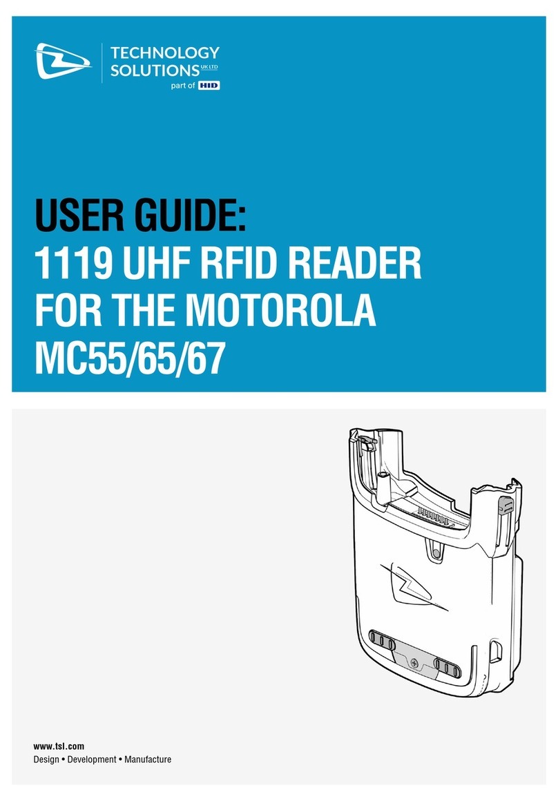
Chase CARD READER User manual

d
Product
Description
CHASE CARD READER
Versatile mobile card reader
CARD READER BASE
Countertop charging base
INSTALLATION GUIDE
MOBILE CARD READER
CHASE CARD READERTM &BASE

WARNING
Before using the Device
⚫Please charge the device for 12 hours before initial use.
⚫Please ensure the unit was not stored for over three months without charging.
⚫Battery life will depend on different use-cases and the battery manufacturer
recommends replacing it with a new one every 2 years.
Caution: Do NOT attempt to open and disassemble the device to cause device tamper and violet the
warranty.
■CHASE CARD READER Power spec:
Input: 5V DC, 1A
■READER CHARGING BASE Power spec:
Input: 5V DC, 2A
Caution: Use only the AC adapter approved and provided by XAC Automation
Corporation for use with this device. Use of any other AC adapter may cause a risk of
fire or explosion.
■Device Operating Temperature:
0oC to 40oC
This symbol is intended to alert the user before starting using the Reader.

1. PACKAGE CONTENT
■CHASE CARD READER BOX
•Card reader
•Pogo pin to USB-C charging cable
■CARD READER CHARGING BASE
•Card reader base
•6.5ft (2m) power cable
•5V/2A power adapter
•Base holder plate

2.DEVICE OVERVIEW
2.1 CHASE CARD READER TOP & SIDE VIEW
Description
1
Touch Display & NFC area
2
Magnetic Stripe Reader
3
Smart Card Reader
4
Power Button

2.2 CHASE CARD READER_BOTTOM VIEW
Description
5
Battery Cover
6
Charging Connector
7
Secure Screw Nut
8
T-pin indicator Hole
9
Lanyard Hole
Bottom Cover Removal Warning
When removing the bottom cover for the purposes of changing battery, please remove the
connector gentilely. .
CAUTION:
RISK OF EXPLOSION IF BATTERY IS REPLACED BY AN INCORRECT TYPE. DISPOSE OF USED
BATTERIES ACCORDING TO THE INSTRUCTIONS.
Warning for internal battery pack
To reduce risk of fire or burns:
1. Do not attempt to open, disassemble, or service the battery pack.
2. Charging the battery periodically to ensure the charge/discharge characteristics.

2.3 CHASE CARD READER_INSIDE VIEW
Description
9
Battery Connector
10
Battery Pack
11
SAM Card Slot
12
Reset key
2.4 READER CHARGING BASE_TOP VIEW

Description
1
Power LED (Blue)
2
Charging Connector
3
Secure Screw
4
T-pin indicator
2.5 READER CHARGING BASE_BOTTOM VIEW

Description
4
USB-C Power Connector
5
Base Holder Slot
6
Base Holder Anchor Positioning Hole
7
Secure Screw (keep Chase Card Reader on the Charging
Base)
8
Power Cable Slot
9
Base Holder Plate
3. HOW TO POWER ON THE READER
Press the power key >3 seconds as shown on Figure 6 until hearing the beep sound
and the display on. Press the power key >5 seconds to power off the device.
4. HOW TO DO THE PAYMENT TRANSACTION
4.1 CONTACTLESS READER
Tap your card onto the EMV contactless logo shown on display to do the transaction.
The virtual LED on display shows the payment progress. Shown as Figure 7.

4.2 SMART CARD READER
Insert your credit card with the ICC chip upward into the card slot and push it to the
end as below Figure 8.
4.3 MAGNETIC STRIPE READER
Swipe your credit card with the magnetic stripe up facing the device. You can swipe
the card bi-directionally as below Figure 9.

5. HOW TO OPEN BATTERY COVER FOR REPLACEMENT
Use the finger or the pen point to push the battery cover to right side as below
Figure 11 to release the battery cover from the reader body to replace the battery
or SAM card.
6. HOW TO PLACE READER ON THE BASE
Align the smart card slot with the LED light guide of Charging Base. Gently press the
reader on the Charging Base and make sure the T-pin and the charging Pogo pin
contacts of the Charging Base well with the Reader as shown on Figure 12.

7. HOW TO LOCK READER TO THE BASE
After placing the Reader onto the Base, turn over the full set to find the secure
screw. Use one cent US dollar coin or screw drive to lock the device as shown on
Figure 13.
8. HOW TO LOCK/REMOVE THE BASE TO THE HOLDER
Step#1: Peel off the adhesive tape overlay (shown as the grey area in Figure 14)
from the bottom of Base Holder Plate, and place the mounting kit on a clean table
surface where it wanted to be installed.
Step#2: Align the Base holder and anchor positioning pin. Then put the Charging
Base above the Base Holder Plate. Shown as Figure 15
Note: The FRONT refers to the LED light guide of Charging Base for customer facing.

Step#3: Push the Charging Base from the front side to fix it with the Base Holder.
Pull it back to remove the Base from the desktop as Figure 16.
9. HOW TO PLUG IN THE BASE
Use the 6.5ft (2m) power cable provided in the charging base box to connect the base
to the 5V/2A power adapter.
Locate the L-shaped plug and plug it into the bottom of the base as shown in Figure
17.

Figure 18 shows the incorrect method of using the straight plug into the base.
Insert the straight plug into the power adapter, as shown in Figure 19.

Federal Communication Commission Interference Statement
This device complies with Part 15 of the FCC Rules. Operation is subject to the following two
conditions: (1) This device may not cause harmful interference, and (2) this device must accept any
interference received, including interference that may cause undesired operation.
Note: This equipment has been tested and found to comply with the limits for a Class A digital device,
pursuant to part 15 of the FCC Rules. These limits are designed to provide reasonable protection
against harmful interference when the equipment is operated in a commercial environment. This
equipment generates, uses, and can radiate radio frequency energy and, if not installed and used in
accordance with the instruction manual, may cause harmful interference to radio communications.
Operation of this equipment in a residential area is likely to cause harmful interference in which case
the user will be required to correct the interference at his own expense.
FCC Caution: Any changes or modifications not expressly approved by the party responsible for
compliance could void the user's authority to operate this equipment.
Radiation Exposure Statement:
The product complies with the FCC portable RF exposure limit set forth for an uncontrolled
environment and are safe for intended operation as described in this manual. The further RF exposure
reduction can be achieved if the product can be kept as far as possible from the user limb or set the
device to lower output power if such function is available.
This transmitter must not be co-located or operating in conjunction with any other antenna or
transmitter.
This manual suits for next models
1
Table of contents
