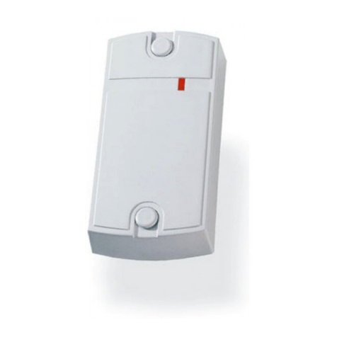
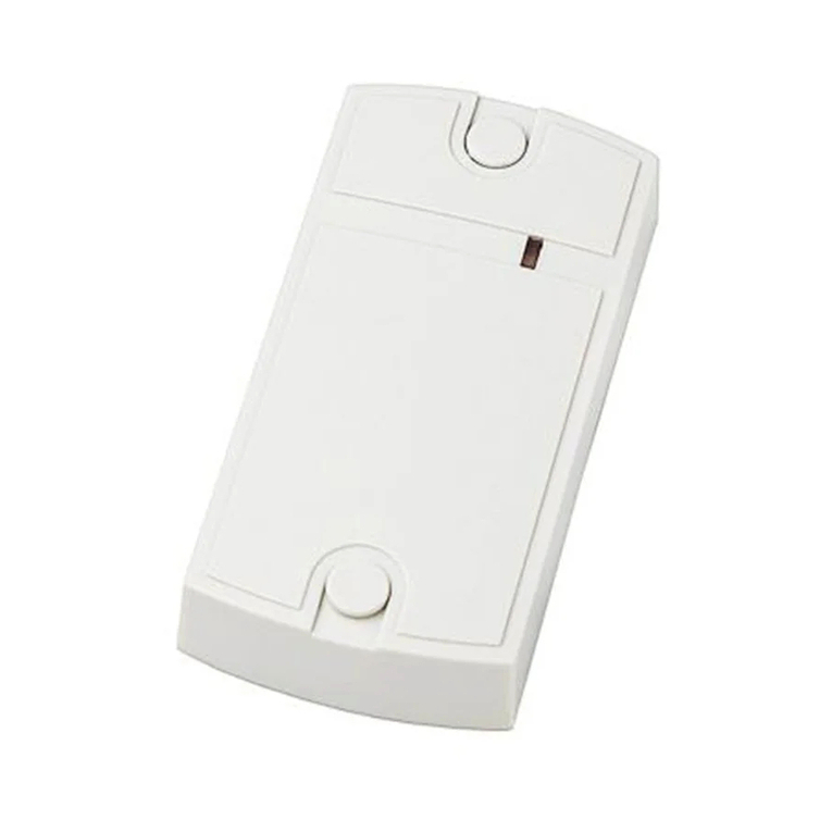
Iron logic Matrix IV EHT Metal User manual

Matrix IV EHT Metal
EM-Marine / HID ProxCard II / Atmel (T5557) 125kHz RFID Reader
with connection via iButton (1-Wire) / Wiegand-26/42 protocols
User Manual
1. OVERVIEW
Matrix IV EHT Metal Reader is used in Access Control Systems (ACS). The reader transfers EM-
Marine, HID ProxCard II or Atmel (T5557) token codes into controller, via iButton (Dallas Touch
Memory) or Wiegand-26/Wiegand-42 protocols.
Special features:
- Reader can distinguish the original ID cards from their cloned copies. This allows to disable
transferring the numbers of cloned cards into controller, at the reader level. Such reading mode is
dubbed “anti-clone”.
- Reader case is made of Silumin for increased anti-vandalism protection.
2. MOUNTING AND CONNECTION
The reader should be mounted on a flat surface at a place where proximity cards can directly
approach the reader (see Figure 1).
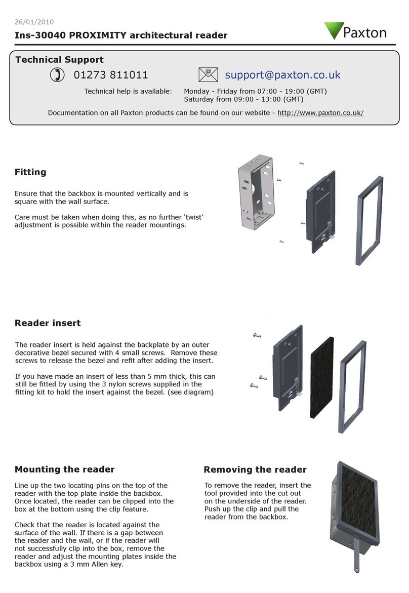
To mount the reader, perform the following steps:
- Unscrew the screw at the bottom of the case and remove the back lid.
- Apply the back lid to the wall, to mark mounting holes locations.
- Drill the holes.
- Screw the back lid to the wall.
- Mount the reader and attach it with the screw at the case bottom.
- Connect the wires as per Table 1.
- To select the protocol for data transfer to controller, connect DATA0 and DATA1 wires as per
Figure 2.
- Insulate all the wires junctions.
- Power on the reader and verify its proper operation by touching it with a card.
Notes:
1. Do not install the readers within 10 cm from one another.
2. To work at specified line distance to controller, please use a UTP cable (e.g. a CAT5e cable).
- When connecting via iButton, one wire of a twisted pair connects to GND and another to DATA0
terminals.
- When connecting via Wiegand, first twisted pair connects to GND and DATA0, and the second
to GND and DATA1 (See Figure 2).
Matrix IV EHT Metal www.ironlogic.me
page 1
Figure 2. Choosing the transmission protocol.
Figure 1. Device Dimensions.
DATA1
GND
D0DATA0
D1
GND
D0iButton
D1
GND
D0iButton
D1
iButton (One-time transmission)
Wiegand
iButton (DS1990A emulation)
ACS controller
Reader
GND
GND
GND
20 mm
58 mm
120 mm

page 2
Table 1. Connection to controller.
3. OPERATION
Using Proximity cards or key fobs:
When a token enters the reader working zone, its token ID is acquired. If successful, it is
acknowledged by a short green LED blink and a buzzer signal. The white LED shines while the card
stays within working zone. The acquired code is transferred to the controller in iButton (Dallas Touch
Memory) or Wiegand-26/Wiegand-42 format, depending on the chosen transmission protocol.
Anti-clone reading mode:
In Anti-clone reading mode, when a cloned card type Atmel (T5557) is presented, the reader produces
a low-tone buzzer signal, but does not transfer the code to the controller. To activate the Anti-Clone
mode, refer to Table 2, Reader settings.
Internal indication:
The visual indication on the reader comprises four LEDs: red, green, blue and white, and audial
indication is done through a built-in buzzer.
The blue LED comes up after powering up the reader and keeps blinking for 3...5 sec, while waiting for
firmware update command. Then red LED comes up the reader is now in stand-by for card mode.
White LED indicates that a card is found within working zone. A short blink of the green LED along with
one buzzer signal indicate successful card reading.
External indication:
The reader allows for external indication control for red and green LEDs and the built-in buzzer.
When managed by the controller, external control is performed by shorting the corresponding
indication control input to common wire (-). External indication control can work alongside internal
indication control, so that only the channel where an external control signal was received at least once,
would switch to external control, and the rest will stay under internal control.
Synchronisation.
When two readers are installed closer than 20 cm from one another, they must be synchronised.
Connect blue wires (SYNC) on the readers for that. This will ensure that the readers operate correctly
even under interference.
Matrix IV EHT Metal www.ironlogic.me
Wire colour
Wire Purpose
Red
+12 V
Black
GND -
Common
Green
DАТА0
White
DАТА1
Orange
LED-G -
Green LED external control
Brown
LED-R -
Amber LED external control
Yellow
BEEP -
Buzzer external control
Blue
SYNC –
Reader synchronisation

4. CONFIGURATION
Before use, please review the factory defaults for parameters (see Table 2). If they need changing, or
on the contrary, restore to factory defaults is needed, a reader setup must be performed. Please note
that setup procedure will change all three configuration parameters, and not just one or two, even if
they are already at desired values.
Entering configuration mode:
1) Power off the reader.
2) Connect wires according to desired values for all three parameters from Table 2 (do not connect the
blue wire!)
3) Power on the reader.
4) It will produce one sound, then two shorter sounds, and then a long one, which keeps sounding
(and green LED is shining) until the reader is powered off.
5) Power off the reader, disconnect the wires.
The new values for the configuration parameters have now been applied.
Table 2. Configuration parameters selection by coloured wires.
Note: BOLD values are factory defaults.
Reverting to factory defaults:
1) Power off the reader.
2) Connect ALL the wires except Power +12V (Red), to the common wire GND (Black).
3) Power on the reader.
4) The reader issues one beep, then three short beeps, then one long beep which will sound until the
power is taken off, along with shining green LED.
5) Power off the reader, disconnect the wires.
The factory defaults have now been restored.
page 3
Matrix IV EHT Metal www.ironlogic.me
Colours
Result
Blue
Not in use –
do
not
connect
Wiegand Protocol Bit Width
Orange + Green
Wiegand-26 (3 bytes)
Orange + White
Wiegand-42 (5 bytes)
iButton
Protocol Bit Width
Brown + Green
5-byte iButton
Brown + White
3-byte iButton
Anti-Clone Mode
Yellow + Green
Anti-Clone ON
Yellow + White
Anti-Clone OFF

5. SPECIFICATIONS
Working frequency: ..................................................................................................125 kHz;
Supported token types: ..............................EM-Marine, HID ProxCard II and Atmel (T5557);
Reading distanse: .......................................................................................................2 -8 cm;
Output interfaces: ...................iButton (Dallas Touch Memory), Wiegand-26 or Wiegand-42;
Maximum line distance to controller by protocol:
- iButton (Dallas Touch Memory) ........................................................................... 15 m;
- Wiegand: ........................................................................................................... 100 m;
Power supply voltage: .............................................................................................. 12 V DC;
Consumption current: ........................................................................................max 150 mA;
Operation mode indication: ........................................................................Audial and Visual;
External indication control: .........................................................................Audial and Visual;
Casing materials: ...........................................................................................Silumin, Plastic;
Dimensions, mm: ..............................................................................................120 x 58 x 20;
6. PACKAGE CONTENTS
Matrix IV EHT Metal Reader: ...............................................................................................1
7. OPERATING CONDITIONS
Ambient temperature: -30…40°C.
Humidity: ≤ 98% at 25°C.
When operating under non-recommended conditions, device parameters can deviate from
specified values.
The reader must be operated in absence of: precipitation, direct sunlight, sand, dust, and
moisture condensation.
8. LIMITED WARRANTY.
This Device is covered by limited warranty for 24 months since the purchase date.
The warranty becomes void, if:
- this Manual's guidelines are not followed;
- the device has suffered physical damage;
- the device has visible traces of exposure to moist and/or aggressive chemicals;
- the device circuits have visible traces of tampering by unauthorised parties.
Under this warranty, the Manufacturer shall repair the device or replace any broken parts as
required, free of charge, in cases where the fault is caused by a Manufacturer's defect.
page 4
Matrix IV EHT Metal www.ironlogic.me
9. CONTACTS
Authorized representative in the European Union
ICONTROL SIA
Slokas iela 79A, LV-1007, Riga, Latvia
E-mail: info@icontrol.lv
Phone: +37124422922
www.ironlogic.me
page 5
The symbol of crossed-throught waste bin on wheels means that the product
must be disposed of at f separate collection point. This also applies to the product
and all accessories marked with this symbol. Products labeled as such must not
be disposed of with normal household waste, but should be taken to a collection
point for recycling electrical and electronic equipment. Recycling helps to reduce
the consumption of raw materials, thus protecting the environment.
Matrix IV EHT Metal www.ironlogic.me
Table of contents
Other Iron logic RFID System manuals

Iron logic
Iron logic Z-2 USB MF User manual

Iron logic
Iron logic Matrix II EH User manual

Iron logic
Iron logic CP-Z-3 E User manual

Iron logic
Iron logic CP-Z-1 GSM User manual

Iron logic
Iron logic Matrix V User manual

Iron logic
Iron logic Matrix II User manual

Iron logic
Iron logic CP-Z 2MF User manual

Iron logic
Iron logic MATRIX-V Instruction manual

Iron logic
Iron logic Matrix-IV RF User manual