ECS Z270-LIGHTSABER User manual

Z270-LIGHTSABER
Version:1.0
40-012-KY7100

Z270-LIGHTSABER USER MANUAL
i
Preface
Copyright
This publication, including all photographs, illustrations and software, is protected
under international copyright laws, with all rights reserved. Neither this manual, nor
any of the material contained herein, may be reproduced without written consent of
the author.
Version 1.0
Disclaimer
The information in this document is subject to change without notice. The
manufacturer makes no representations or warranties with respect to the contents
hereof and specifically disclaims any implied warranties of merchantability or
fitness for any particular purpose. The manufacturer reserves the right to revise this
publication and to make changes from time to time in the content hereof without
obligation of the manufacturer to notify any person of such revision or changes.
Trademark Recognition
Microsoft, MS-DOS and Windows are registered trademarks of Microsoft Corp.
MMX, Pentium, Pentium-II, Pentium-III, Celeron are registered trademarks of Intel
Corporation.
Other product names used in this manual are the properties of their respective owners
and are acknowledged.
Federal Communications Commission (FCC)
This equipment has been tested and found to comply with the limits for a Class B
digital device, pursuant to Part 15 of the FCC Rules. These limits are designed to
provide reasonable protection against harmful interference in a residential
installation. This equipment generates, uses, and can radiate radio frequency
energy and, if not installed and used in accordance with the instructions, may cause
harmful interference to radio communications. However, there is no guarantee that
interference will not occur in a particular installation. If this equipment does cause
harmful interference to radio or television reception, which can be determined by
turning the equipment off and on, the user is encouraged to try to correct the
interference by one or more of the following measures:
•Reorient or relocate the receiving antenna
•Increase the separation between the equipment and the receiver
•Connect the equipment onto an outlet on a circuit different from that to
which the receiver is connected
•Consult the dealer or an experienced radio/TV technician for help
Shielded interconnect cables and a shielded AC power cable must be employed with
this equipment to ensure compliance with the pertinent RF emission limits
governing this device. Changes or modifications not expressly approved by the
system’s manufacturer could void the user’s authority to operate the equipment.

Z270-LIGHTSABER USER MANUAL
ii
Canadian Department of Communications
This class B digital apparatus meets all requirements of the Canadian Interference-
causing Equipment Regulations.
Cet appareil numérique de la classe B respecte toutes les exigences du Réglement
sur le matériel brouilieur du Canada.
Declaration of Conformity
This device complies with part 15 of the FCC rules. Operation is subject to the
following conditions:
•This device may not cause harmful interference.
•This device must accept any interference received, including interference
that may cause undesired operation.
Electromagnetic compatibility of multimedia equipment -
Emission requirements
EN 55032
EN 61000-3-2 Electromagnetic Compatibility(EMC)
Part 3-2: Limits-Limits for harmonic current emissions (equipment
input current 16A per phase)
EN 61000-3-3 Electromagnetic Compatibility(EMC)
Part 3-3: Limits-Limitation of voltage changes, voltage fluctuations
and flicker in public low-voltage supply systems, for equipment
with rated current 16A per phase and not subject to conditional
connection
EN 55024 Information technology equipment-Immunity characteristics-
Limits and methods of measurement
EN 60950 Safety for information technology equipment including
electrical business equipment
CE marking
This device is in conformity with the following EC/EMC directives:

Z270-LIGHTSABER USER MANUAL
iii
Chapter 6
Trouble Shooting
Provides basic trouble
shooting tips.
page 77
The manual consists of the following:
Describes features of the
motherboard.
page 1
Describes installation of
motherboard components.
page 9
page 29
page 69
Installing the Motherboard
Introducing the Motherboard
Provides information on
using the BIOS Setup Utility.
Describes the motherboard
software.
About the Manual
Chapter 4
Chapter 1
Chapter 2
Chapter 3
Using BIOS
Using the Motherboard Software
Describes the AMD
CrossfireTM Technology.
page 73
Chapter 5
AMD CrossfireTM Technology
Support

Z270-LIGHTSABER USER MANUAL
iv
Memo

Z270-LIGHTSABER USER MANUAL
v
Chapter 2 9
Installing the Motherboard 9
Safety Precautions.............................................................................9
Installing the Motherboard in a Chassis......................................9
Installing Hardware.................................................................10
Installing the Processor...........................................................10
Installing the CPU Cooler.........................................................12
Installing Memory Modules....................................................13
Installing Add-on Cards...........................................................15
Connecting Optional Devices..................................................17
Installing a SATA Hard Drive...................................................23
Connecting Case Components.......................................................24
Front Panel Header.................................................................27
TABLE OF CONTENTS
Preface i
Chapter 1 1
Introducing the Motherboard 1
Introduction...................................................................................1
Package Contents.........................................................................1
Specifications................................................................................2
Motherboard Components..........................................................4
I/O Ports...............................................................................................6
Chapter 3 29
Using BIOS 29
About the Setup Utility........................ .......................................29
The Standard Configuration........................ ...........................29
Entering the Setup Utility........................................................29
Resetting the Default CMOS Values.....................................30
Using BIOS.......................................................................................30
BIOS Navigation Keys..............................................................31
Main Menu.............................................................................32
Advanced Menu......................................................................33
Chipset Menu..........................................................................47
M.I.B.X (MB Intelligent BIOS X) Menu....................................54
Security Menu.........................................................................65
Boot Menu..............................................................................66
Exit Menu................................................................................67
Updating the BIOS...................................................................68

Z270-LIGHTSABER USER MANUAL
vi
Chapter 4 69
Using the Motherboard Software 69
Auto-installing under Windows 7/8.1/10.......................................69
Running Setup.........................................................................69
Manual Installation..........................................................................71
ECS Utility Software (Intelligent EZ Utility)....................................71
Chapter 5 73
AMD CrossFireTM Technology Support 73
Requirements...................................................................................73
Installing CrossFireTM graphics cards........................................73
The CatalystTM Control Center Dialog Box..................................75
To Enable CrossFireTM..............................................................75
Chapter 6 77
Trouble Shooting 77
Start up problems during assembly..............................................77
Start up problems after prolong use............................................78
Maintenance and care tips..............................................................78
Basic Troubleshooting Flowchart...................................................79
POST Code Checkpoints 81

1
Z270-LIGHTSABER
USER MANUAL
Chapter 1
Chapter 1
Introducing the Motherboard
Introduction
Thank you for choosing the Z270-LIGHTSABER motherboard. This motherboard is a
high performance, enhanced function motherboard designed to support the
LGA1151 socket for Intel®Kaby Lake/Skylake processor.
This motherboard is based on Intel®®
®®
®Z270 Express Chipset for best desktop platform
solution. It supports up to 64 GB of system memory with dual channel DDR4
3200+(OC)/2133 MHz. High resolution graphics via three PCIe x16 Gen3 slots. It
supports 3-way AMD CrossfireXTM technology that allows you to install Multi graphic
cards with identical GPU running at PCIe Gen3 speed. In additon, four PICe x1 Gen 3
slots are for extending usage.
It integrates USB 2.0, USB 3.0 and USB 3.1 interface, supporting up to seven USB 2.0
ports (four USB 2.0 ports at rear panel and one 2*5 pin USB 2.0 header supports
additional two USB 2.0 ports and one 5 pin USB 2.0 header supports additional one
USB 2.0 port) and six USB 3.0 ports (four USB 3.0 ports at the rear panel and one USB
3.0 header supports additional two USB 3.0 ports) and two USB 3.1 ports at the rear
panel. The Front USB 3.0 header provides EZ charger technology, please refer to Front
Panel USB 3.0 headers of chapter 2 for more details.
The motherboard is equipped with advanced full set of I/O ports in the rear panel,
including PS/2 keyboard and mouse combo connector, one CLR_CMOS button, one
Optical SPDIF out port, one HDMI 1.4b port, one Display port, two USB 3.1 ports, four
USB 3.0 ports, four USB 2.0 ports (the yellow ports only used for game USB 2.0
keyboard and mouse, while the red ports only used for rezound vigor USB 2.0 device),
one RJ45 LAN connector and 8-ch audio jacks.
In addition, this motherboard supports six SATA 6Gb/s connectors for expansion.
Your motherboard package ships with the following items:
Package Contents
Z270-LIGHTSABER Motherboard
Quick Installation Guide
User Manual
DVD
I/O Shield
4 SATA 6Gb/s cable
The package contents above are for reference only, please take the actual package items as
standard.

Chapter 1
2
Z270-LIGHTSABER
USER MANUAL
CPU
Specifications
• Dual-channel DDR4 memory architecture
• 4 x 288-pin DDR4 DIMM sockets support up to 64 GB
• Supports DDR4 3200+(OC)/2133 MHz SDRAM
Memory
• SATA3_1/2 supported by Asmedia ASM1061 Chipset
• SATA3_3/4/5/6 Supported by Intel®Z270 Express Chipset
• 1 x U.2 Port (PCI-e x4 only)
Expansion
Slots
Storage
• 1 x PS/2 keyboard and mouse combo connector
• 1 x CLR_CMOS button
• 1 x Optical SPDIF out port
• 1 x HDMI 1.4b port
• 1 x Display port
• 2 x USB 3.1 ports
• 4 x USB 3.0 ports
• 4 x USB 2.0 ports*
• 1 x RJ45 LAN connector
• 1 x 8-ch Audio jacks
Rear Panel I/O
LAN • Killer E2500
• Realtek ALC1150 8-Ch High Definition audio CODEC
- Compliant with HD audio specification
Audio
• LGA1151 socket for Intel®Kaby Lake/Skylake processor
• Supports max CPU TDP 95W and MB TDP designs up to 280W
Note: Please go to ECS website for the latest CPU support list.
Note: Please go to ECS website for the latest Memory support list.
AMDCrossFireXTM
Technology
• Supports AMD CrossFireXTM Technology
• 3 x PCI Express x16 Gen3 slots*
• 4 x PCI Express x4 Gen3 slots
• 1 x M.2 Socket 3 with M key, supports type 2242/2260/2280
storage devices (both PCIE & SATA mode)
• Intel®Z270 ChipsetChipset
• Asmedia ASM1061 & Asmedia ASM1142Extra Chip
Note: *The yellow ports only used for game USB 2.0 keyboard and
mouse, while the red ports only used for rezound vigor USB 2.0
device.
Note:
*1. Please insert your PCIe Card (VGA card) on gray PCIEX16 slot
(PCIEX16_1) when you use one PCIe Card (VGA card), please
referer to Chapter 2-3-4.
2. If inserting two PCIe Cards (VGA card) into PCIEX16_1 and
PCIEX16_2 slots, both two slots will run at X8 mode.
3. If inserting three PCIe Cards (VGA card) into PCIEX16_1~3 slots,
the PCIEX16_1 and PCIEX16_2 will run at X8 mode, while the
PCIEX16_3 will run at x4 mode.
3
Z270-LIGHTSABER
USER MANUAL
Chapter 1
• AMI BIOS with 64Mb SPI Flash ROM
• Supports Plug and Play, STR (S3)/ STD(S4), Hardware Monitor
• Supports ACPI & DMI
• Audio, LAN, can be disabled in BIOS
• F7 hot key for boot up devices option
• Supports Over-Clocking
• Supports PgUp clear CMOS Hotkey (Has PS2 KB Model only)
• Add the function of copying BIOS parameters to USB flash drive
System BIOS
• ATX Size, 305mm x 244mmForm Factor
Bundled
Software
Support
Internal I/O
Connectors &
Headers
• 1 x 24-pin ATX Power Supply connector
• 1 x 8-pin ATX 12V Power connector
• 2 x 4-pin CPUFAN connectors
• 2 x 4-pin SYSFAN connectors
• 1 x 4-pin PWRFAN connector
• 1 x 5-pin USB 2.0 header supports additional one USB 2.0 port
• 1 x 2*5 pin USB 2.0 header supports additional two USB 2.0
ports
• 1 x USB 3.0 header supports additional two USB 3.0 ports
(supports EZ charger)
• 6 x SATA 6Gb/s connectors
• 1 x U.2 connector (PCIEx4 Signal only)
• 1 x 80 Port switch button
• 1 x Debug POST LEDs
• 1 x Reset button
• 1 x Power on button
• 1 x ROM backup button
• 1 x BIOS updat button
• 1 x BIOS set button
• 1 x Quick OC button
• 1 x Front Panel switch/LED header
• 1 x Case open header
• 1 x Buzzer header
• 1 x Front Panel audio header
• 1 x SPIROM Switch
• ECS Exclusive AP: eBLU*/eDLU/eSF*
Note: *Microsoft.NET Framework 4.5 is required.

Chapter 1
4
Z270-LIGHTSABER
USER MANUAL
Motherboard Components
5
Z270-LIGHTSABER
USER MANUAL
Chapter 1
Table of Motherboard Components
LABEL COMPONENTS
1. CPU Socket
LGA1151 socket for
Intel
®
Kaby Lake/Skylake processor
2. CPUFAN1 4-pin CPU cooling fan connector
3. DIMM1~4 288-pin DDR4 Module slots
4. 80P_SW 80 Port switch button
5. POST POST Code, Voltage and Temperature LED
6. POWER Power on button
7. RESET Reset button
8. ATX_POWER Standard 24-pin ATX power connector
9. SYSFAN1 4-pin system cooling fan connector
10. USB3F Front panel USB 3.0 header (supports EZ Charger)
11. U2_MINI_SAS U.2 connector
12. SATA3_1~6 Serial ATA 6Gb/s connectors
13. BZ Buzzer header
14. M2_2280M M.2 M.2 Socket 3 with M key, supports type
2242/2260/2280 storage devices (both PCIE & SATA
mode)
15. SPIROM_SW SPIROM switch
15. F_PANEL Front panel switch/LED header
17. ROM_BACKUP ROM backup button
18. F_USB2 5-pin front panel USB 2.0 header
19. CASE CASE open header
20. F_USB1 2*5 pin front panel USB 2.0 header
21. BIOS_UPDATE BIOS update button
22. BIOS_SET BIOS set button
23. QUICK_OC Quick OC button
24. SYSFAN2 4-pin system cooling fan connector
25. PWR_FAN 4-pin Power cooling fan connector
26. F_AUDIO Front panel audio header
27. PCIEX16_1~3 PCI Express x16 Gen3 slots for graphics interface
28. PCIE1~4 PCI Express x1 Gen3 slots
29. CPUFAN2 4-pin CPU cooling fan connector
30. ATX_12V 8-pin +12V power connector
Chapter 1
6
Z270-LIGHTSABER
USER MANUAL
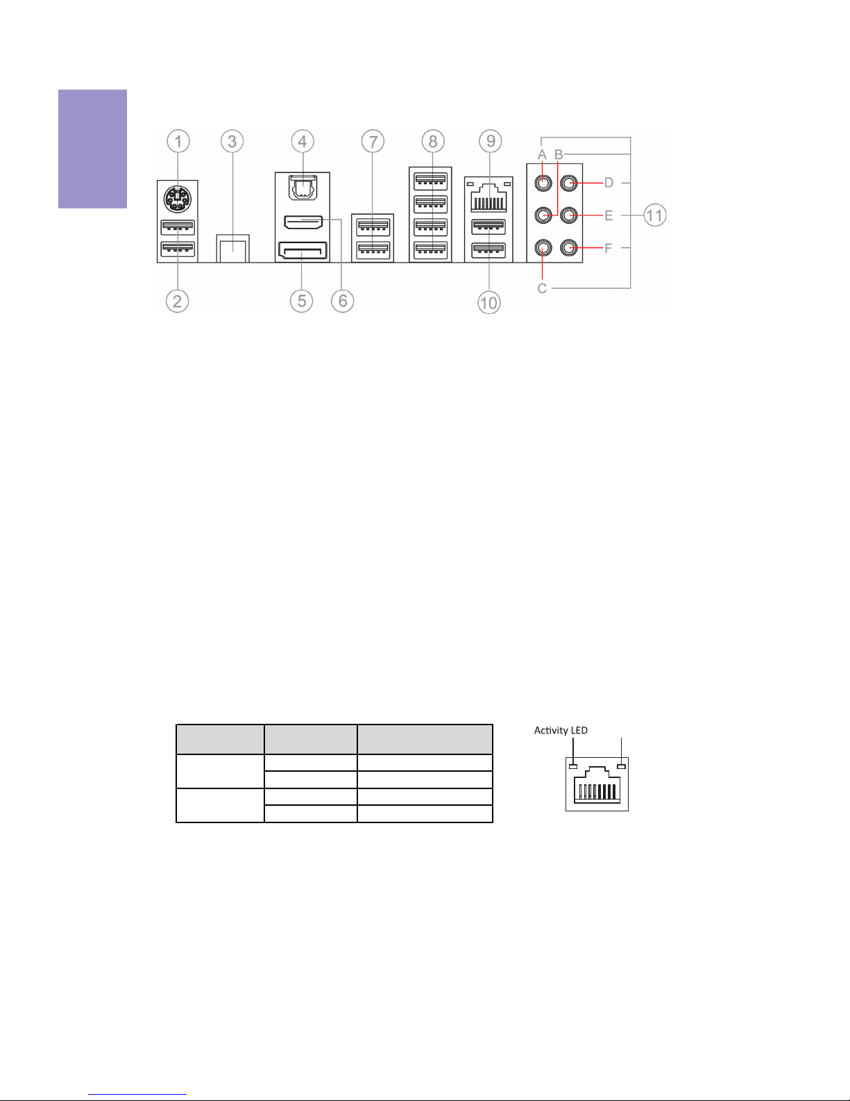
I/O Ports
1. PS/2 Keyboard & Mouse Combo connector
Use the PS/2 port to connect a PS/2 Keyboard or Mouse.
2. USB 2.0 Ports (Yellow)
This two USB 2.0 ports are only used to connect game keyboard and mouse.
3. CLR_CMOS_BTN
Use the CLR_CMOS button to clear CMOS.
4. Optical SPDIF Out port
This jack connects to external optical digital audio out devices.
5. DP Port
Connect your monitor to the DP port.
6. HDMI 1.4b Port
You can connect the display device to the HDMI 1.4b port.
7. USB 3.1 Ports
Use the USB 3.1 ports to connect USB 3.1 devices.
8. USB 3.0 Ports
Use the USB 3.0 ports to connect USB 3.0 devices.
9. LAN Port
Connect an RJ-45 jack to the LAN port to connect your computer to the Network.
10. USB 2.0 Ports (Red)
This two USB 2.0 ports are only used for rezound vigor USB 2.0 device.
LAN LED Status Description
OFF No data
Green blinking Active
OFF No link
Green Link
Activity LED
Link LED
Link LED
LAN Port
11. Audio ports
Use the audio jacks to connect audio devices. The D port is for stereo line-in signal,
while the F port is for microphone in signal. This motherboard supports 8-channel
audio devices that correspond to the A, B, C and E port respectively. In addition, all
of the 3 ports, B, C and E provide users with both right & left channels individually.
Users please refer to the following note for specific port function definition.
7
Z270-LIGHTSABER
USER MANUAL
Chapter 1
A: Center & Woofer D: Line-in
B: Back Surround E: Front Out
C: Side Surround F: Mic
The above port definition can be changed to audio input or audio output by changing the
driver utility setting.
Table of onboard Buttons
Item name PCB mark Function
EZ LED Display 80P_SW
When this button collocates with the 7-segment
display on the MB, it will display the following
information about the MB, and it will switchover
in the following order.
1. POST_CODE
2. CPU_VOLTAGE (V)
3. DIMM_VOLTAGE (V)
4. CPU_TEMP (℃)
5. PCH_TEMP (℃)
EZ Quick OC QUICK_OC
Your computer will process the fast OverClocking
automatically after pressing this button under OS
and rebooting the computer.
EZ Enter BIOS BIOS_SET
Under OS or DOS, after pressing this button, your
computer will directly enter the BIOS setup
picture when you reboot or turn on your
computer next time.
EZ Update BIOS BIOS_UPDATE
Store the BIOS in USB Flash Drive
(ex:60216iG.ROM), and change the file name to
EBOOT.ROM, then when you reboot your
computer, the BIOS will be updated after pressing
this button under OS with the USB Flash Drive
connected to the computer.
EZ Duo BIOS ROM_BACKUP
When the SPIROM_A used for booting is
damaged:
1. Disconnect AC PWR for more than 30s and
push the SPIROM_SW to side B, then connect AC
PWR, if the ROM_LED remains on, it shows that
SPIROM_B is selected. Boot the computer to
enter BIOS Disable Eup Function, the computer
will reboot automatically after saving the setup,
then press the POWER button to turn off the
computer. And then press ROM_BACKUP for more
than 4s, if ROM_LED blinks continually, it shows
that F75223 is backuping the file from SPIROM_B
into SPIROM_A. Backup is finished if ROM_LED
returns to remain on after 30s.
2. Disconnect AC for more than 30s, then push
SPIROM_SW to side A, system will return to
default state.

Chapter 1
8
Z270-LIGHTSABER
USER MANUAL
Item name PCB mark Function
BIOS Update:
1. Update SPIROM_A: ensure that SPIROM_SW is
on the side A after disconnecting AC for more
than 30s, then connect AC PWR, boot the
computer to enter BIOS Disable Eup Function,
Disable ME Control, the computer will reboot
automatically after saving the setup, then
update BIOS according to normal process.
2. Update SPIROM_B: ensure that SPIROM_SW is
on the side B after disconnecting AC for more
than 30s, then connect AC PWR, boot the
computer to enter BIOS Disable Eup Function,
Disable ME Control, the computer will reboot
automatically after saving the setup, then
update BIOS according to normal process.
EZ SPIROM Switch SPIROM_SW
SPIROM_A: Default BIOS
SPIROM_B: Backup BIOS
BIOS Backup:
1. Disconnect AC PWR for more than 30s and
push the SPIROM_SW to side B, then connect AC
PWR, if the ROM_LED remains on, it shows that
SPIROM_B is selected. Boot the computer to
enter BIOS Disable Eup Function, the computer
will reboot automatically after saving the setup,
then press the POWER button to turn off the
computer. And then press ROM_BACKUP for
more than 4s, if ROM_LED blinks continually, it
shows that F75223 is backuping the file from
SPIROM_B into SPIROM_A. Backup is finished if
ROM_LED returns to remain on after 30s.
2. Disconnect AC for more than 30s, then push
SPIROM_SW to side A, system will return to
default state.
Confirmation of SPIROM_A and SPIROM_B BIOS
version:
Ensure that SPIROM_SW is on the side A/B after
disconnecting AC for more than 30s, and press
CLR_CMOS_BTN button, then to confirm it after
booting the computer.
EZ RESET RESET Your computer will fast reset after pressing this
button.
EZ POWER POWER This is power button.
EZ Clear CMOS CLR_CMOS_BTN
This button is used to clear CMOS. Please
perform this operation after disconnecting the
AC PWR for more than 30s.

Chapter 2
9
Z270-LIGHTSABER USER MANUAL
Chapter 2
Installing the Motherboard
2-1. Safety Precautions
2-2. Installing the motherboard in a Chassis
This motherboard carries an ATX form factor of 305 x 244 mm. Choose a chassis that
accommodates this form factor. Make sure that the I/O template in the chassis
matches the I/O ports installed on the rear edge of the motherboard. Most system
chassis have mounting brackets installed in the chassis, which corresponds to the
holes in the motherboard. Place the motherboard over the mounting brackets and
secure the motherboard onto the mounting brackets with screws.
Follow these safety precautions when installing the motherboard:
• Wear a grounding strap attached to a grounded device to avoid damage
from static electricity.
• Discharge static electricity by touching the metal case of a safely grounded
object before working on the motherboard.
• Leave components in the static-proof bags.
• Always remove the AC power by unplugging the power cord from the power
outlet before installing or removing the motherboard or other hardware
components.
Do not over-tighten the screws as this can stress the motherboard.
When installing 24-pin ATX power cable, please note the overhead space
because of the chassis design of the Motherboard, avoiding to damage the
motherboard with excessive power.

Chapter 2
10
Z270-LIGHTSABER USER MANUAL
2-3. Installing Hardware
2-3-1. Installing the Processor
• This motherboard has an LGA1151 socket.
• When choosing a processor, consider the performance requirements of
the system. Performance is based on the processor design, the clock speed
and system bus frequency of the processor, and the quantity of internal
cache memory and external cache memory.
• You may be able to change the settings in the system Setup Utility. We
strongly recommend you do not over-clock processor or other
components to run faster than their rated speed.
• The following illustration shows CPU installation components.
A. Press the hook of lever down with your thumb and pull it to the right
side to release it from retention tab.
B. Lift the tail of the load lever and rotate the load plate to fully open
position.
C. Grasp the edge of the package substrate. Make sure pin 1 indicator
is on your bottom-left side. Aim at the socket and place the package
carefully into the socket by purely vertical motion.

Chapter 2
11
Z270-LIGHTSABER USER MANUAL
D. Rotate the load plate onto the package IHS (Intergraded Heat
Spreader). Engage the load lever while pressing down lightly onto the
load plate. Secure the load lever with the hook under retention tab. Then
the cover will flick automatically.
Please save and replace the cover onto the CPU socket if processor is
removed.

Chapter 2
12
Z270-LIGHTSABER USER MANUAL
A. Apply some thermal grease onto the contacted area between the
heatsink and the CPU, and make it to be a thin layer.
B. Fasten the cooling fan supporting base onto the CPU socket on the
motherboard. And make sure the CPU fan is plugged to the CPU fan
connector.
C. Connect the CPU cooler power connector to the CPU_FAN connector.
2-3-2. Installing the CPU Cooler
• Install the cooling fan in a well-lit work area so that you can clearly see the
motherboard and processor socket.
• Avoid using cooling fans with sharp edges in case the fan casing and the
clips cause serious damage to the motherboard or its components.
• To achieve better airflow rates and heat dissipation, we suggest that you
use a high quality fan with 3800 rpm at least. CPU fan and heat sink
installation procedures may vary with the type of CPU fan/heatsink
supplied. The form and size of fan/heatsink may also vary.
• DO NOT remove the CPU cap from the socket before installing a CPU.
• Return Material Authorization (RMA) requests will be accepted only if the
motherboard comes with the cap on the LGA1151 socket.
• The following illustration shows how to install CPU fan.

Chapter 2
13
Z270-LIGHTSABER USER MANUAL
2-3-3. Installing Memory Modules
• This motherboard accommodates four memory modules. It can support
four 288-pin DDR4 3200+(OC)/2133 MHz.
• Do not remove any memory module from its antistatic packaging until
you are ready to install it on the motherboard. Handle the modules only
by their edges. Do not touch the components or metal parts. Always wear
a grounding strap when you handle the modules.
• You must install at least one module in any of the four slots. Total memory
capacity is 64 GB.
• Refer to the following to install the memory modules.
The four DDR4 memory sockets (DIMM1, DIMM2, DIMM3 and DIMM4) are divided
into two channels and each channel has two memory sockets as following:
Channel A: DIMM1, DIMM2
Channel B: DIMM3, DIMM4
C. The slot latche is levered upwards and latch on to the edges of the
DIMM.
A. Push the latche on the mobilizable side of the DIMM slot down.
B. Install the DIMM module into the slot and press it firmly down until it
seats correctly. Check that the cutouts on the DIMM module edge
connector match the notches in the DIMM slot.
Table of contents
Other ECS Motherboard manuals


