Chatillon LG Series User manual

- 1 -
CHATILLON®LG Series
Mechanical Force Gauge
Operating Instructions
Instruction Manual NC002711
January 2003
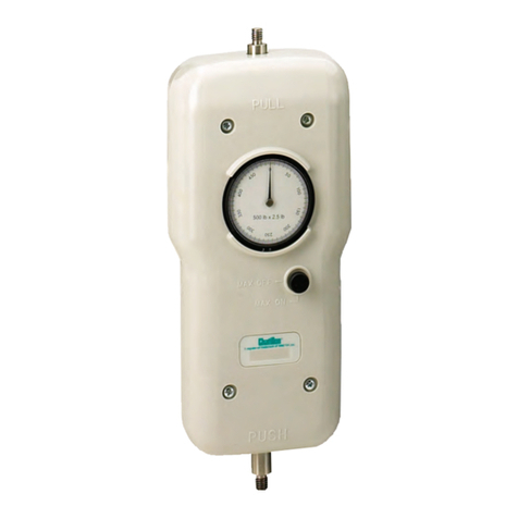
TheLGSeriesmechanicalforcegauge
is ideal for a wide range of force test-
ing applications. Based on our popu-
lar DPP Series force gauge, the LG
Seriesfeaturesalarger,2.25-inchdial
for improved resolution and readabil-
ity,peakholdbutton,ergonomicshape
and improved accuracy of +0.5% of
full scale. The LG gauge is an excel-
lent, economical solution for tensile or
compression testing.
The durable, plastic housing fits natu-
rally in the hand for a comfortable and
firm grip even at maximum loads.
Gauges may be mounted to a test
stand for even greater control and con-
sistent results in repetitive testing ap-
plications. Easy to read concentric
dial measures clockwise direction
only. Dial rotates 360-degrees for tar-
ing. Apeak hold button capturespeak
readings. Available in lbf, kgf or N
units of measure. LG Series gauges
come complete with protective carry-
ing case and a set of stainless steel
attachments. A Certificate of Calibra-
tion with Data is supplied standard.

- 2 -
OPERATION
Thezeropointofthegaugemaynotalwaysbe in the 12 o’clock position
due to gravity effects and the weight of fixtures or grips on the force
gauge shaft. To zero the gauge, rotate the bezel on the dial indicator so
that the indicator pointer lines up with the zero on the dial face. On the
lighter model force gauges (5 LBF, 2KGF, 20N or less), gently tap the
gauge to overcome static friction when taking readings.
Gauges are designed for axial loading. Ensure the load is not applied at
anangleoranerrorcanbeintroducedinthe force readings. The gauges
are designed to have a 10% tare for fixtures and grips. If this 10% tare
is exceeded, the force gauge may not measure up to full scale.
CAUTION
The LG Series is a unidirectional force gauge. When applying a load
to the instrument the dial indicator MUST rotate in the clockwise
direction.
Compression Testing
For compression testing, as-
semble the appropriate attachment
or grip to the bottom shaft of the
force gauge. For compression
testing the shaft should be pushed
intothegauge,causingtheindica-
tor to rotate in the clockwise direc-
tion. Attachments should be ap-
plied “finger-tight”. Do NOT over-
tighten.
Tensile Testing
For tension testing, assemble the
appropriate hook, attachment or
grip to the top shaft of the force
gauge. For tension testing the
shaft should be pulled out of the
top of the force gauge, causing
the indicator to rotate in the
clockwise direction. Attachments
should be applied “finger-tight”.
Do NOT overtighten.

- 3 -
CAUTION
Do not apply a load to the LG Series force gauge so the indicator
rotates in the counterclockwise direction. If excessive loads are
applied in the counterclockwise direction, damage may occur to the
force gauge.
PEAK HOLD
The LG Series force gauge has
a maximum hold feature. This
allows the peak force to be held
after the load is removed.
Activate Peak Hold
To activate this feature, rotate the
knob to “MAX ON” position.
Reset Peak Hold
Toresetthereading,simplyrotate
the switch to “MAX OFF” and then
returnbackto“MAXON”position.
To deactivate this feature, rotate
the knob to the “MAX OFF” posi-
tion.
SPECIFICATIONS
Accuracy: +0.5% of Full Scale
Overload Capacity: 110% of Rated Capacity
Maximum Overload: 150% of Rated Capacity
Tare Capacity: 10% of Rated Capacity
Dial Resolution: 0.5% of Full Scale
Deflection: 10mm (.394 inches) at Full Scale
Operating Temperature: +40°F to +110°F (+5°C to +45°C)
Instrument Weight: 1.5 lbs (0.67 kg)
Shipping Weight with case: 3.5 lbs (1.59 kg)
Warranty: 2 Years

- 4 -
TEST STAND MOUNTING
The LG Series force gauge has two #10-32 female threads for
mounting to CHATILLON test stands. Ensure the #10-32 screws are
not too long, otherwise it may bind and damage the force gauge.
The screw thread length going into the back of the gauge should not
exceed 3/8 inch.
The force gauge also has four M3 x 0.5 threaded holes for alternative
mounting.

- 5 -
ORDERING INFORMATION
SPK-FMG-008A Chisel Point
SPK-FMG-009A Point
SPK-FMG-010A Notch
SPK-FMG-011A Flat
SPK-FMG-012A1Hook, Stationary, 50 lbf
SPK-FMG-012B1Hook, Stationary, 100 lbf
SPK-FMG-013A Extension Rod,6-inch
NC002710 Carrying Case
NC002711 Operator’s Manual
ML38672Hook, Swivel, 20 lbf
ML38502Hook, Swivel, 100 lbf
NC000988-32Extension Rod, 3”
Model Capacity x Resolution
Decimal Dials (LBF) Metric Dials (KGF)
LG-002 2 x 0.01 lbf
LG-005 5 x 0.025 lbf
LG-010 10 x 0.05 lbf
LG-020 20 x 0.1 lbf
LG-030 30 x 0.15 lbf
LG-050 50 x 0.25 lbf
LG-075 75 x 0.375 lbf
LG-100 100 x 0.5 lbf
LG-1KG 1 x 0.005 kgf
LG-2KG 2 x 0.01 kgf
LG-3KG 3 x 0.015 kgf
LG-5KG 5 x 0.025 kgf
LG-10KG 10 x 0.05 kgf
LG-20KG 20 x 0.1 kgf
LG-30KG 30 x 0.15 kgf
LG-50KG 50 x 0.25 kgf
LG-10N 10 x 0.05 N
LG-20N 20 x 0.1 N
LG-30N 30 x 0.15 N
LG-50N 50 x 0.25 N
LG-100N 100 x 0.5 N
LG-200N 200 x 1 N
LG-300N 300 x 1.5 N
LG-500N 500 x 2.5 N
Model Capacity x Resolution
S.I. Dials (Newtons)
Model Capacity x Resolution
ACCESSORIES
Part No. Description
Notes: 1Capacity dependent.
2 Optional accessories.
MAINTENANCE
Gauge accuracy should be checked periodically to ensure the gauge is
within its calibration limits. The calibration can be verified by applying
known weights (adjusted for local gravity) to the extension hook. If
adjustment is required, the gauge should be returned to AMETEK for
calibration.

- 6 -
SPARE PARTS
Dial Indicator Assembly, LG-002 NC002677-01
Dial Indicator Assembly, LG-005 NC002677-02
Dial Indicator Assembly, LG-010 NC002677-03
Dial Indicator Assembly, LG-020 NC002677-04
Dial Indicator Assembly, LG-030 NC002677-05
Dial Indicator Assembly, LG-050 NC002677-06
Dial Indicator Assembly, LG-075 NC002677-07
Dial Indicator Assembly, LG-100 NC002677-08
Dial Indicator Assembly, LG-1KG NC002677-13
Dial Indicator Assembly, LG-2KG NC002677-14
Dial Indicator Assembly, LG-3KG NC002677-15
Dial Indicator Assembly, LG-5KG NC002677-16
Dial Indicator Assembly, LG-10KG NC002677-17
Dial Indicator Assembly, LG-20KG NC002677-18
Dial Indicator Assembly, LG-30KG NC002677-19
Dial Indicator Assembly, LG-50KG NC002677-20
Dial Indicator Assembly, LG-10N NC002677-24
Dial Indicator Assembly, LG-20N NC002677-25
Dial Indicator Assembly, LG-30N NC002677-26
Dial Indicator Assembly, LG-50N NC002677-27
Dial Indicator Assembly, LG-100N NC002677-28
Dial Indicator Assembly, LG-200N NC002677-29
Dial Indicator Assembly, LG-300N NC002677-30
Dial Indicator Assembly, LG-500N NC002677-31
Bezel, Dial Indicator NC002716
Bearing Support Assembly NC002715
Top Case (Housing) NC002713
Bottom Case (Housing) NC002714
Maximum Peak Hold Knob Assembly NC002678
Gauge Mounting Plate NC002671
Label, Gauge Model NC002621
Ball Bushing 2630
Retaining Ring, Ball Bushing 13007
Description Part Number
Description Part Number
Description Part Number
Description Part Number

- 7 -
PRODUCT WARRANTY
This instrument is warranted against defects in workmanship, material and design for two (2) years
from the date of delivery to the extent that AMETEK will, at its sole option, repair or replace the
instrumentoranypartthereofwhichisdefectiveprovided,however,thatthewarrantyshallnotapply
to instruments subjected to tampering or abuse, or exposed to highly corrosive conditions.
THIS WARRANTY IS IN LIEU OF ALL OTHER WARRANTIES WHETHER EXPRESS OR IMPLIED
AND AMETEK HEREBY DISCLAIMS ALL OTHER WARRANTIES, INCLUDING, WITHOUT
LIMITATION, ANY WARRANTY OF FITNESS FOR A PARTICULAR PURPOSE OR MERCHANT-
ABILITY. AMETEK SHALL NOT BE LIABLE FOR ANY INCIDENTAL OR CONSEQUENTIAL
DAMAGES, INCLUDING, BUT NOT LIMITED TO, ANY ANTICIPATED OR LOST PROFITS.
Thiswarranty is voidableif thepurchaser failstofollow anyand allinstructions,warnings orcautions
in the instrument’s operation manual.
If a manufacturing defect is found, AMETEK will replace or repair the instrument or replace any
defective part thereof without charge; however, AMETEK’s obligation hereunder does not include
the cost of transportation which must be borne by the customer. AMETEK assumes no responsibility
for damage in transit, and any claims for such damage should be presented to the carrier by the
purchaser.

- 8 -
Pub No. NC002711
Issued 01/03
Information within this document is
subject to change without notice. ISO9001
Manufacturer
AMETEKTestandCalibration
Instruments Division
8600 Somerset Drive
Largo, Florida 33773
USA
Tel +1-727-536-7831
Tel +1-800-527-9999 (USA only)
Fax +1-727-539-6882
Asia Pacific
AMETEK Lloyd Instruments
No.7 Sherwood Place
AlexanderHeights
6064 Perth
Australia
Tel +61-8-9343-5725
Fax +61-8-9343-5723
AMETEK Singapore Pvt. Ltd.
10 Ang Mo Kio Street 65
#05-12 TECHPOINT
Singapore
569059
Tel +65 484 2388
Fax +65 481 6588
AMETEK Lloyd Instruments
Forum House
12Barnes Wallis Road
Segensworth East
Fareham
Hampshire PO 15 5TT
Tel +44 (0) 1489-486399
Fax +44 (0) 1489-8851118
AMETEK Lloyd Instruments SA
3 Avenue des Coudriers
Zoned’Activite de l’Observatoire
7810 Montigny-Le-Bretonneux
France
Tel +33-1-3057-4774
Fax +33-1-3057-5033
AMETEK Precision
Instruments Europe GmbH
Rudolf-Diesel-Strasse 16
D-40670,Meerbusch
Germany
Tel +49-2-159-9136 0
Fax +49-2-159-9136 39
Americas Europe
TEST AND CALIBRATION INSTRUMENTS
AMETEK and CHATILLON are registered
trademarks of AMETEK, Inc.
LLOYD INSTRUMENTS is an AMETEK Inc.
trademark
Internet Addresses:
www.ametek.com
www.chatillon.com
www.lloyd-instruments.co.uk
Printed in U.S.A.Copyright 2003, by AMETEK, Inc.

This manual suits for next models
24
Table of contents
Other Chatillon Measuring Instrument manuals
Popular Measuring Instrument manuals by other brands
Chauvin Arnoux
Chauvin Arnoux C.A 6545 user manual
National Instruments
National Instruments 9235 Getting started guide
KROHNE
KROHNE OPTISONIC 6300 quick start
Brüel & Kjær
Brüel & Kjær 2245 instruction manual
Honeywell
Honeywell NOTIFIER UDS-3 USER MANUAL, INSTALLING AND OPERATING MANUAL
Sierra
Sierra QuadraTherm 640i Series quick start guide
