Chatsworth Products VD Series User manual

Chatsworth Products. (CPI)
User Manual for Double Conversion Online UPS / 5kVA-8kVA 12/23v1
1
User Manual for
Double-Conversion
Online UPS
VD-Series
5kVA –8kVA, 3-Phase Models
Version 1
December 2023
While every effort has been made to ensure the accuracy of all information, CPI does not accept liability for any
errors or omissions and reserves the right to change information and descriptions of listed services and products.
©2023 Chatsworth Products, Inc. All rights reserved. Chatsworth Products, Clik-Nut, CPI, CPI Passive Cooling,
CUBE-iT, Secure Array, eConnect, Evolution, GlobalFrame, MegaFrame, QuadraRack, RMR, Saf-T-Grip,
SeismicFrame, SlimFrame, TeraFrame, Motive, EuroFrame, Oberon, Velocity and ZetaFrame are federally
800-834-4969 registered trademarks of Chatsworth Products. H-Plane, Hi-Bar, In-Plane, M-Frame, NetPoint, Simply Efficient,
chatsworth.com Skybar, and Wi-Tile and are trademarks of Chatsworth Products. All other trademarks belong to their respective

Chatsworth Products. (CPI)
User Manual for Double Conversion Online UPS / 5kVA-8kVA 12/23v1
2
Table of Contents
1 Safety .................................................................................................... 4
2 Installation. ........................................................................................... 5
2.1 Initial Inspection. ..................................................................... 5
2.2 Installation Environment........................................................... 5
2.3 Unpacking. .............................................................................. 6
2.4 Model Configuration ................................................................. 7
2.5 Exterior ..................................................................................... 7
2.6 Internal Mechanisms ................................................................ 10
2.7 Power Cable ............................................................................ 11
2.8 Wiring ....................................................................................... 12
2.9 2 Slot Rackmount Chassis Installation ..................................... 13
2.10 Power Module/Battery Pack Installation .................................. 14
3 Power Module LCD Descriptions ......................................................... 16
3.1 PowerModule ............................................................................ 16
3.2 UPS System Functional Description .......................................... 18
4 Operation ................................................................................................ 22
4.1 AC Startup ................................................................................... 22
4.2 Cold Start Startup (Start up with no AC Power Pressed) ............. 24
4.3 Turn Off Operation ........................................................................ 26
4.4 Battery Mode Turn Off Operation .................................................. 28
4.5 Maintenance Bypass Switch Operation ......................................... 29
5 Control Panel and Display Description ......................................................... 31
5.1 LCD Screen in UPS Module .......................................................... 31
5.2 Operation Menu............................................................................ 33

Chatsworth Products. (CPI)
User Manual for Double Conversion Online UPS / 5kVA-8kVA 12/23v1
3
6Troubleshooting..................................................................................... 48
7 Specifications ........................................................................................ 52
8 Obtaining Service................................................................................... 53
9 CPI limited Warranty .............................................................................. 54

Chatsworth Products. (CPI)
User Manual for Double Conversion Online UPS / 5kVA-8kVA 12/23v1
4

Chatsworth Products. (CPI)
User Manual for Double Conversion Online UPS / 5kVA-8kVA 12/23v1
5
1 Safety
1.1 Important Safety Instructions
This UPS contains LETHAL VOLTAGES. All repairs and service must be performed by AUTHORIZED SERVICE
PERSONNEL ONLY. There are NO USER SERVICEABLE PARTS inside the UPS.
WARNING:
•The UPS designed for commercial and industrial purpose, it is forbidden to apply for any life
sustainment and support.
•The UPS system contains its own energy source. The output terminals may carry live voltage
even when UPS is disconnected to an AC source.
•To reduce the risk of fire or electrical shock, UPS installation has to be in a controlled room
where temperature and humidity are monitored. Ambient temperature must not exceed 40°C.
The system is only for indoor use.
•Ensure all power is disconnected before installation or service.
•Service and maintenance should be performed by qualified personnel only.
Before working on this circuit
•Isolate Uninterruptible Power System (UPS).
•Then check for Hazardous Voltage between all terminals including the protective earth.
Risk of Voltage Back feed
The isolation device must be able to carry the UPS input current.
1.2 EMC
WARNING:
This is a product for commercial and industrial application in the second environment - installation restrictions or
additional measures may be needed to prevent disturbances.
1.3 Installation Information
WARNING:
•Installation must be performed by qualified personnel only.
•The cabinets must be installed on a level floor suitable for computer or electronic equipment.
•The UPS cabinet is heavy. If unloading instructions are not closely followed, cabinet may cause
serious injury.
•Do not tilt the cabinets more than 10 degree.
•Before applying electrical power to the UPS, make sure the Ground conductor is properly
installed.
•Installation and Wiring must be performed in accordance with the local electrical laws and
regulations.
•The disconnection device should be chosen based on the input current.

Chatsworth Products. (CPI)
User Manual for Double Conversion Online UPS / 5kVA-8kVA 12/23v1
6
1.4 Maintenance
•Only qualified service personnel should perform the battery installation.
•The following PRECAUTIONS should be observed:
1. Remove watches, rings, or other metal objects. Use tools with insulated handles.
2. Wear rubber gloves and boots.
3. Do not lay tools or metal parts on top of batteries or battery cabinet
4. Disconnect the charging source prior to connecting or disconnecting terminal.
5. Check if the battery is inadvertently grounded. If it is, remove the source of grounding. Contacting
with any part of the ground might result in electrical shock. The likelihood of such shock can be
prevented if such grounds are removed during installation and maintenance.
•UPS is designed to supply power even when disconnected from the utility power. After disconnect the util-
ity and DC power, authorized service personnel should attempt internal access to the UPS.
•Do not disconnect the batteries while the UPS is in Batterymode.
•Disconnect the charging source prior to connecting or disconnecting terminals.
•Batteries can result in a risk of electrical shock or burn from high short circuit current.
•When replacing batteries, use the same number of sealed, lead-acid batteries.
•Do not open or mutilate the battery. Release electrolyte is harmful to the skin and eyes, and may be toxic.

Chatsworth Products. (CPI)
User Manual for Double Conversion Online UPS / 5kVA-8kVA 12/23v1
7
1.5 Recycling the Used Battery
•Do not dispose of the battery in a fire. Battery may explode. Proper disposal of battery is required. Refer
to your local codes for disposal requirements.
•Do not open or mutilate the battery. Released electrolyte is harmful to the skin and eyes. It may be toxic.
•Do not discard the UPS or the UPS batteries in the trash. This product contains sealed, lead-acid batteries
and must be disposed properly. For more information, contact your local recycling/reuse or hazardous
waste center.
•Do not discard waste electrical or electronic equipment (WEEE) in the trash. For proper disposal, contact
your local recycling/reuse or hazardous waste center.
2 Installation
2.1 Initial Inspection
1. Visually examine if there is any damage inside and outside of packages in the process of the transportation. If
any damage, report it to the carrier immediately.
2. Verify the product label and confirm the consistency of the equipment.
3. If the equipment needs to be returned, carefully repack the equipment by using the original packing material
that came with.
2.2 Installation Environment
1. The UPS is designed for indoor use only and should be located in a clean environment with adequate
ventilation to keep the environmental parameters within the required specification.
2. Make sure that transportation routes (e.g. corridor, door gate, elevator, etc.) and installation area can
accommodate and bear the weight of the UPS, the external battery cabinet and handling equipment.
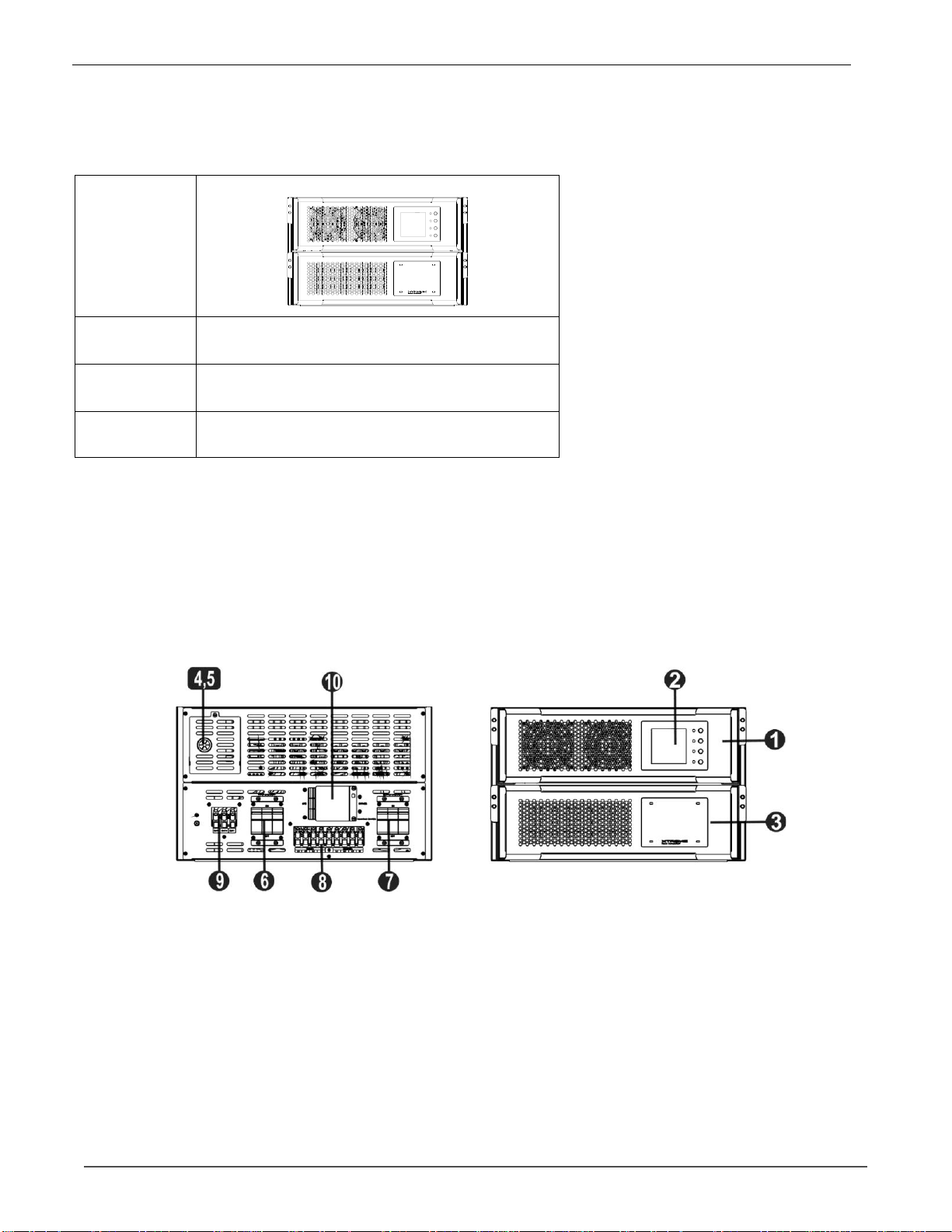
3. The UPS uses forced convection cooling by internal fans. Cooling air enters the module through ventilation
grills located at the front of the cabinet and exhaustedthrough grills located in the rear part of the cabinet. Please
do not block the ventilation holes.
4. Ensure that the installation area is spacious for maintenance and ventilation.
5. Keep the temperature of installation area around 30°C and humidity within 90%. The highest operating
altitude is 5,200 ft above sea level.
6. If necessary, install a system of room extractor fans to avoid formation of room temperature. Air filters are
necessary if the UPS is operated in a dusty environment.
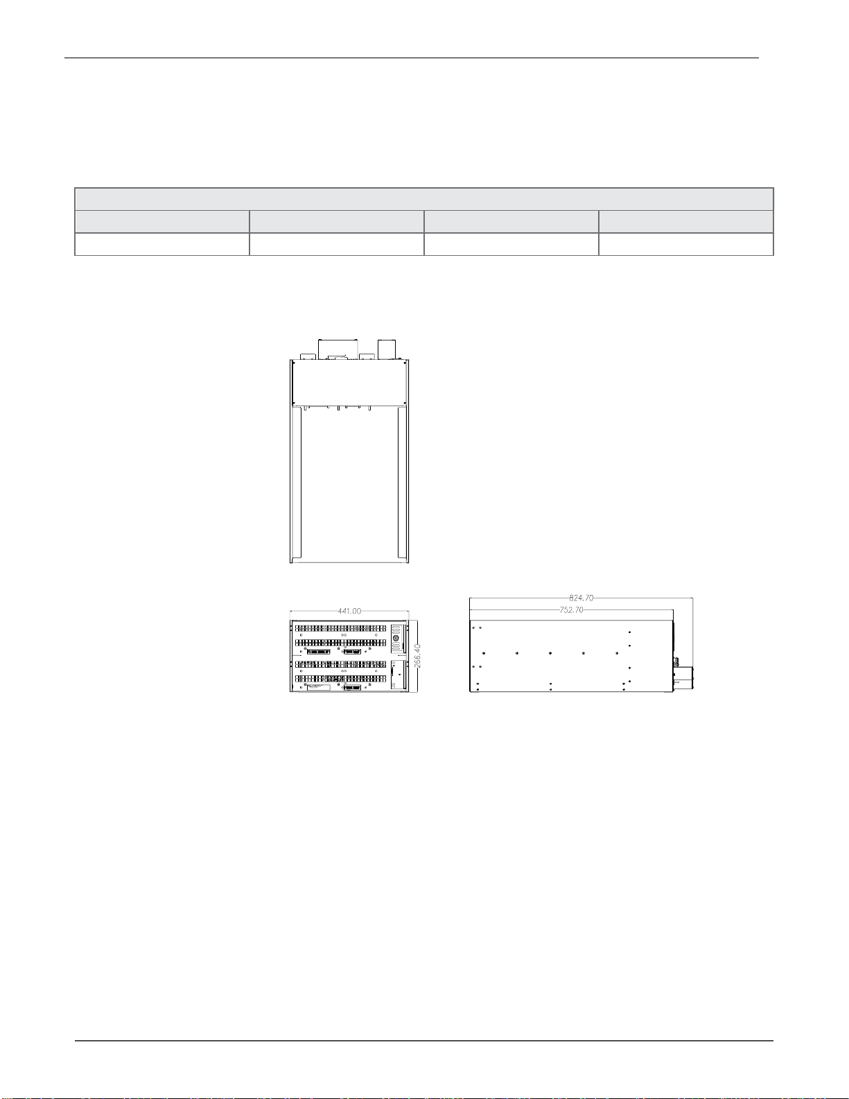
7. It is recommended that you parallel the external battery cabinets to the UPS. The following instructions of
clearances are suggested:
•Keep a clearance of 40” from the top of the UPS for maintenance, wiring and ventilation.
•Keep a clearance of 36" back clearance, or install flex-conduit to allow for moving of cabinet to access
switches. When pushed toward wall, leave 6" of clearance for ventilation.
•Front clearance should be per local and NEC code.
8. For safety concerns, we suggest that you shall:
•Equip with CO2 or dry powder fire extinguishers near the installation area.
•Install the UPS in an area where the walls, floors and ceilings were constructed of fireproof materials.
9. Do not allow unauthorized personnel to enter the installation area. Assign specific personnel to keep the
UPS key.

Chatsworth Products. (CPI)
User Manual for Double Conversion Online UPS / 5kVA-8kVA 12/23v1
8
2.3 Unpacking
1. Unload the box to installed area, remove the tape and open box;
3. Take out the enclosure after removal of the cushion packing material;
Terminal Block for AC input L21-20P or L21-30P for AC input

Chatsworth Products. (CPI)
User Manual for Double Conversion Online UPS / 5kVA-8kVA 12/23v1
9
2.4 Model Configuration
Photo
UPS
Module
#
Max of 1 (Slot 1 ONLY)
Battery
Module #
Max of 1
Cabinet
Height
10.5” (6U)
2.5 Exterior
In the front of the UPS, Power Module slots and Battery Module slots. A wiring terminal blocks, circuit breakers,
communication ports are located at the back of cabinet. The side panels are locked by screws. The casters at the
bottomof the UPS cabinet can be used to move the UPS for short distances.
NOTE: The two slot chassis is intended to mount in a rack and doesn’t have casters or leveling feet.
Caster kit available as optional adder.
2 Slot
M90C
1. Power module
2. LCD display on
Power module
3. Battery module
4. Intelligent slot
5. Emergency power off port
6. AC input breaker
7. AC output breaker
8. AC terminal
9. External battery terminal
10. Maintenance bypass switch

Chatsworth Products. (CPI)
User Manual for Double Conversion Online UPS / 5kVA-8kVA 12/23v1
10
2.5.1 Mechanical Data
Dimension
s
UPS cabinet
Width
Dep
th
Height
2 Slot
17.4”
30.6”
10.5”
6U Rack
2 Slot Chassis

Chatsworth Products. (CPI)
User Manual for Double Conversion Online UPS / 5kVA-8kVA 12/23v1
11
2.5.2 Front / Rear Open View
Front open view: After removing panel covers, you will see the empty module slots and control panel.
Rear open view: You will see the breakers, terminal blocks, receptacle panels, and communication ports installed
on the cabinet.
Front View Rear View
1. Control panel
2. Power/battery module slots
3. Communication port
4. AC terminals
5. DC terminals
6. AC input breakers
7. MBS behind display. See section 4.5
8. AC output breakers

Chatsworth Products. (CPI)
User Manual for Double Conversion Online UPS / 5kVA-8kVA 12/23v1
12
2.6 Internal Mechanisms
2.6.1 Breakers
At the rear panel of the cabinet, you can see AC Input/Output breakers as 2.5.2 show.
2.6.2 Wiring Terminal Blocks
Remove all panel covers and you will see the wiring terminal block for the UPS input/output wiring, please check
below chart and table.
Terminal Block Descriptions
Item
Function
Description
AC
Terminal
Output Block (O/P-L1, O/P-
L2, O/P-L3, O/P-N)
Connects the
Critical loads
Includes L1, L2, L3 and Neutral terminals.
AC Input Block
(I/P-L1, I/P-L2, I/P-
L3, N)
Connects main AC
source
Includes L1, L2, L3 and Neutral terminals.
For UPS Grounding
(PE)
For UPS grounding
Includes one grounding terminal - PE.
DC
Terminal
DC Terminal Block
(BAT+, BAT-N, BAT-)
Connects an
external battery
pack
Includes
Positive (+), Negative (-) and Neutral
(N) terminals.
AC Terminal DC Terminal

Chatsworth Products. (CPI)
User Manual for Double Conversion Online UPS / 5kVA-8kVA 12/23v1
13
2.7 Power Cable
Please follow the local wiring regulations. Follow environmental conditions and refer to IEC60950-1.
2.7.1 AC input and output maximum current, recommended OCPD, and power cable
configuration.
AC Input
Model
5kVA
8kVA
Current (A)
15
24
Recommended OCPD
20
30
Torque force (lb-in)
20
20
AC Output
Model
5kVA
8kVA
Current (A)
14
22
Recommended OCPD
20
30
Torque force (lb-in)
20
20
2.7.2 DC input maximum current and power cable configuration.
Model
5kVA
8kVA
Current (A)
30
46
Recommended OCPD
40
60
Torque force (lb-in)
20
20
Warning:
1. One standard battery module contains 16 pcs of 12V 10Ah batteries (8 pcs Pos+/8pcs Neg-). You must install
at least one battery module per power modules.

Chatsworth Products. (CPI)
User Manual for Double Conversion Online UPS / 5kVA-8kVA 12/23v1
14
2.8 Wiring
•WARNING:
•Before wiring, make sure the AC input and battery power are completely cut off.
•Make sure the breakers, including AC input breaker, AC output breaker and DC breaker, are all in the OFF
position
•If installing two slot chassis please ensure chassis is installed in rack before wiring is installed.
(Refer to section 2.10).
2.8.1 Installation Drawing
UPS Chassis
Wiring
2.8.2 AC source connection
Connect AC input to the AC power source. Please refer to Installation Drawing for UPS wiring.
Polarity of three-phase is critical. A-B-C rotation needs to be used. The wrong polarity will cause an alarm for
UPS system when the UPS is powered.
The Neutral wire must be connected properly. A warning message will be indicated if the Neutral wire is not
connected properly. The UPS will show warning message as “Warning! Bypass Input N Error”. Then the UPS will
transfer to battery mode if battery pack is connected or transfer to standby mode and no output if no battery pack
is connected.

Chatsworth Products. (CPI)
User Manual for Double Conversion Online UPS / 5kVA-8kVA 12/23v1
15
2.8.3 External Battery Pack Connection
After the battery pack is completely installed, be sure to set up nominal battery voltage, battery capacity and maxi-
mum charging current in LCD setting. Otherwise, if battery setting is different from actual installation, the UPS will
keep alarming. Please refer to section 5.1.2 battery settinglist for details.
2.9 2 Slot Rackmount Chassis Installation
Step 1: Install included rail kits into user supplied rack.
Step 2: Install 2 slot chassis on top of installed rail kit in rack. Secure two slot chassis with included brackets and
screws.

Chatsworth Products. (CPI)
User Manual for Double Conversion Online UPS / 5kVA-8kVA 12/23v1
16
Step 3: Install power module into top slot of 2 slot chassis.
Step 4: Install battery module into bottom slot of 2 slot chassis.
Step 5: Connect input and output electrical wiring to terminal block on rear of 2 slot chassis. (Referto section 2.6.2)
2.10 Power Module/Battery Pack Installation
2.10.1 Install the UPS module
Warning: The power modules installed in the same cabinet must be at the same rating.
1. Insert the power module into an unoccupied slot by two persons.
NOTE: The power module must be inserted into a universal slot.
Universal Slots
2 Slot
Chassis
Upper Slot
2 Slot Chassis

Chatsworth Products. (CPI)
User Manual for Double Conversion Online UPS / 5kVA-8kVA 12/23v1
17
2. Secure the UPS module to the cabinet by fixing the screws at the front panel of the UPS module.
2.10.2 Remove the UPS Module
Warning:
Before removing any power module, make sure the remaining power modules can support
the critical loads.
At least one power module MUST stay in the UPS cabinet in case the UPS system is operating in
Maintenance Bypass Mode. (1.)
(1.) Use a screwdriver to remove the four screws from fixing holes.
(2.) Two people pull out together and remove the UPS module from its slot.
2.10.3 Battery Module Installation/Removal
Please follow power module installation/removal steps to install and remove battery packs.
NOTE: Battery modules can be installed in the lower slots.

Chatsworth Products. (CPI)
User Manual for Double Conversion Online UPS / 5kVA-8kVA 12/23v1
18
3. Power Module LCD Descriptions
3.1. Power module
Each power module is shipped with its own package. It has to be installed during the whole system installation. The
capacity of each power module is 5kVA/5kW or 8KVA/8KW. It includes a power factor correction rectifier, a battery
charger, an inverter, a static bypass circuit and control circuit.
No.
Item
Description
1
Fan
The Power Module uses forced convection cooling by these fans. Cooling air enters
the module through ventilation grills at the front of the module and exhalation
exhausts through grills located at the rear of the module. Please do not block the
ventilation area.
2
Battery Start Button
When AC input is not existing, use this button to start battery power for UPS.
3
LCD display
There is LCD display on the UPS module. It can show the UPS information and
the slave UPS information when operating in parallel.
4
Function Keys
There are four function keys in the UPS module. They can control and monitor the
single UPS module. Please refer to function key table for the details.
5
LED indicators
There are four LED indicators to show UPS working status. Please refer to LED
indicator table for the details.

Chatsworth Products. (CPI)
User Manual for Double Conversion Online UPS / 5kVA-8kVA 12/23v1
19
Power Module Interface Display
3.1.2 Power Module Function Key Descriptions
Control key
Press this button to turn on the UPS.
Or press it to confirm the selection in the menu.
Off/ENTER
Press this button to turn on the UPS.
Or press it to confirm the selection in the menu.
OFF/ESC
Press this button to turn off the UPS.
Or press it to return to the last menu.
UP
Press this button to select the previous item in the menu.
Or press this button to jump to previous page in the screen.
Or press this button to increase the number in the setting.
DOWN
Press this button to select the next item in the menu.
Or press this button to jump to next page in the screen.
Or press this button to decrease the number in the setting.
3.1.2 LED indicators for Power module
LED
BYPASS
LINE
BATTERY
ALARM
Mode
UPS Power On
●
●
●
●
Standby mode
○
○
○
○
Bypass mode
●
○
○
○

Chatsworth Products. (CPI)
User Manual for Double Conversion Online UPS / 5kVA-8kVA 12/23v1
20
Line mode / Con-
verter mode
○
●
○
○
Battery mode
○
○
●
○
Fault mode
○
○
○
●
Battery Test mode
○
●
●
○
ECO mode
●
●
○
○
Note: ● means LED is lighting, and ○ means LED is faded
3.2 UPS System Functional Description
The modular and hot-swappable design of power modules makes it a highly convenient replacement solution to
meet your power requirement.
3.2.1 Operation Mode
This modular UPS is three-phase, three-wire plus Neutral + ground on-line, double-conversion and reverse-transfer
UPS that permits operation in the following modes:
• Standby Mode
• Line Mode
• Battery Mode
• Bypass Mode
• ECO Mode
• Shutdown Mode
3.2.2 Standby Mode
Upon connecting to utility input power, the UPS is in Standby mode before UPS is turned on (if BYPASS enable set-
ting is Disabled), and charger function will be active when the battery is present.
UPS power modules
Battery modules
Other manuals for VD Series
1
Table of contents
Other Chatsworth Products UPS manuals
Popular UPS manuals by other brands

Sanyo Denki
Sanyo Denki SANUPS E11B-Li quick start guide

Eaton
Eaton MX 4000 RT Installation and user manual

CyberPower
CyberPower PR1500 user manual

Tripp Lite
Tripp Lite SM750XLNAFTA Specifications

Tripp Lite
Tripp Lite SmartPro SMART500RT1U owner's manual

Tripp Lite
Tripp Lite SmartPro AG-0021 owner's manual

Tripp Lite
Tripp Lite SmartOnline SU2200RMNAFTA Specifications

Delta
Delta Ultron HPH series user manual

PowerWalker
PowerWalker VFI 6000 TGB user manual

Tripp Lite
Tripp Lite OmniSmart OMNI300NAFTA Specification sheet

Tripp Lite
Tripp Lite SmartPro Rackmount SMX1500XLRT2U Features and specifications

Tripp Lite
Tripp Lite SmartOnline 220/380 owner's manual