Chauvet VIP Drive 43s User manual

User Manual

VIP Drive 43s User Manual Rev. 1
EDITION NOTES
The VIP Drive 43s User Manual includes a description, safety precautions, installation, programming,
operation, and maintenance instructions for the VIP Drive 43s as of the release date of this edition.
Trademarks
CHAUVET, the Chauvet logo and VIP Drive 43s are registered trademarks or trademarks of Chauvet &
Sons, LLC (d/b/a Chauvet and Chauvet Lighting) in the United States and other countries. Other company
and product names and logos referred to herein may be trademarks of their respective companies.
Copyright Notice
The works of authorship contained in this manual, including, but not limited to, all design, text and images
are owned by Chauvet.
© Copyright 2016 Chauvet & Sons, LLC. All rights reserved.
Electronically published by Chauvet in the United States ofAmerica.
Manual Use
Chauvet authorizes its customers to download and print this manual for professional information purposes
only. Chauvet expressly prohibits the usage, copy, storage, distribution, modification, or printing of this
manual or its content for any other purpose without written consent from Chauvet.
Document Printing
For best results, print this document in color, on letter size paper (8.5 x 11 in), double-sided. If using A4
paper (210 x 297 mm), configure the printer to scale the content accordingly.
Intended Audience
Any person installing, operating, and/or maintaining this product should completely read through the guide
that shipped with the product, as well as this manual, before installing, operating, or maintaining this
product.
Disclaimer
Chauvet believes that the information contained in this manual is accurate in all respects. However,
Chauvet assumes no responsibility and specifically disclaims any and all liability to any party for any loss,
damage or disruption caused by any errors or omissions in this document, whether such errors or
omissions result from negligence, accident or any other cause. Chauvet reserves the right to revise the
content of this document without any obligation to notify any person or company of such revision, however,
Chauvet has no obligation to make, and does not commit to make, any such revisions. Download the latest
version from www.chauvetprofessional.com.
Document Revision
This VIP Drive 43s User Manual is the 1st edition of this document. Go to www.chauvetprofessional.com
for the latest version.

VIP Drive 43Nova User Manual Rev. 1 i
TABLE OF CONTENTS
1. Before You Begin....................................................................... 1
What Is Included ........................................................................................... 1
Claims........................................................................................................... 1
Manual Conventions ..................................................................................... 1
Symbols ........................................................................................................ 1
Safety Notes.................................................................................................. 2
Personal Safety.............................................................................................................. 2
Mounting ........................................................................................................................ 2
Power and Wiring........................................................................................................... 2
Operation ...................................................................................................... 2
2. Introduction ................................................................................ 3
Description.................................................................................................... 3
Features........................................................................................................ 3
Product Overview.......................................................................................... 3
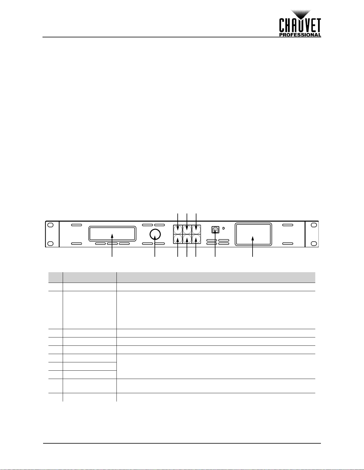
Front Panel Overview..................................................................................................... 3
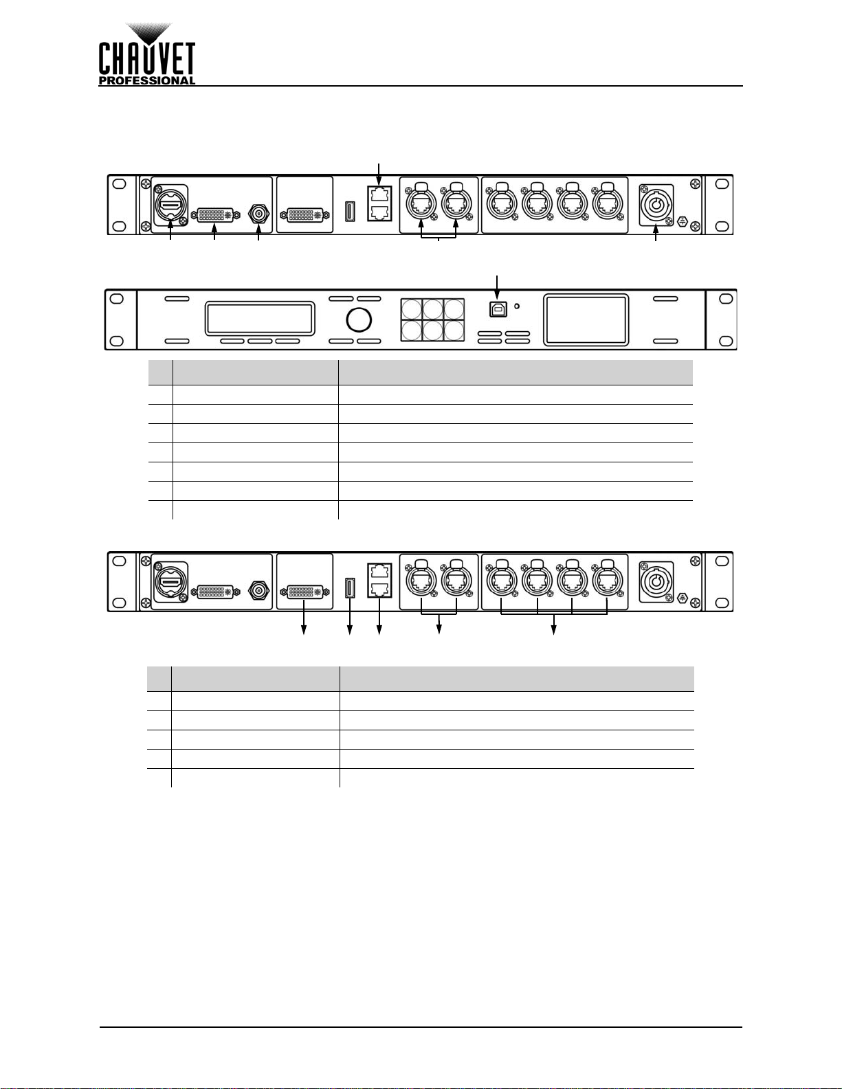
Rear Panel Overview..................................................................................................... 4
Product Dimensions...................................................................................... 4
3. Setup ........................................................................................... 5
AC Power...................................................................................................... 5
AC Plug.......................................................................................................................... 5
Mounting ....................................................................................................... 5
Signal Connections....................................................................................... 5
Video Source Connection .............................................................................................. 5
Computer Connection.................................................................................................... 5
Art-Net™ Connection..................................................................................................... 5
Preview Monitor Connection.......................................................................................... 5
Connection Diagrams..................................................................................................... 6
Input Connections Diagram..................................................................................... 6
Output Connections Diagram .................................................................................. 6
4. Operation .................................................................................... 7
Control Panel Operation................................................................................ 7
Programming................................................................................................. 7
Menu Map..................................................................................................... 7
Operating Settings Configuration.................................................................. 13
Home Screen................................................................................................................. 13
Brightness...................................................................................................................... 14
Front Panel Lock............................................................................................................ 14
Color Adjustments.......................................................................................................... 14
Ethernet.......................................................................................................................... 15
Art-Net™ Start Address........................................................................................... 15
Art-Net™ Universe .................................................................................................. 15
IP Address............................................................................................................... 15
Subnet Mask............................................................................................................ 16
Art-Net™ Values............................................................................................................ 16
Backup........................................................................................................................... 20
Save Configuration.................................................................................................. 21
Load Configuration .................................................................................................. 21
Load One Configuration from USB.......................................................................... 21
Load All from USB................................................................................................... 21
Save All to USB....................................................................................................... 21
Transition ....................................................................................................................... 21

VIP Drive 43Nova User Manual Rev. 1
ii
Deinterlacing............................................................................................................ 21
Image Enhance ....................................................................................................... 22
Fade Type ............................................................................................................... 22
Fade Time ............................................................................................................... 22
Test Pattern.................................................................................................................... 23
Test Pattern Mode................................................................................................... 23
Auto Switch.............................................................................................................. 24
Picture In Picture............................................................................................................ 24
Input Selection......................................................................................................... 24
Position.................................................................................................................... 24
Input Mode............................................................................................................... 25
Swap Inputs............................................................................................................. 25
Display Brightness ......................................................................................................... 25
Video Input..................................................................................................................... 25
Temperature................................................................................................................... 26
Advanced....................................................................................................................... 26
Firmware Version .................................................................................................... 26
Double-tap To Switch .............................................................................................. 26
Preview Output........................................................................................................ 26
Preview DVI Port ..................................................................................................... 26
Factory Reset .......................................................................................................... 27
Customized Button .................................................................................................. 27
Output Format ......................................................................................................... 27
Scale.............................................................................................................................. 27
Horizontal Size ........................................................................................................ 27
Vertical Size............................................................................................................. 28
Horizontal and Vertical Scale .................................................................................. 28
Horizontal Offset...................................................................................................... 28
Vertical Offset.......................................................................................................... 28
Auto Scale ............................................................................................................... 28
Reset Scaling .......................................................................................................... 29
Zoom/Crop Image.................................................................................................... 29
Map................................................................................................................................ 29
Offset Settings......................................................................................................... 29
Position Settings...................................................................................................... 30
Port Tutorial............................................................................................................. 30
Set Width................................................................................................................. 31
Test Grid.................................................................................................................. 31
Mapping by Port ...................................................................................................... 32
5. Technical Information................................................................ 34
Product Maintenance.................................................................................... 34
6. Technical Specifications ........................................................... 35
7. Returns........................................................................................ 36
8. Contact Us .................................................................................. 37

1
VIP Drive 43s User Manual Rev. 1
BEFORE YOU BEGIN
1. BEFORE YOU BEGIN
What Is Included
Claims
Carefully unpack the product immediately and check the container to make sure all the parts are in the
package and are in good condition.
If the box or the contents (the product and included accessories) appear damaged from shipping, or show
signs of mishandling, notify the carrier immediately, not Chauvet. Failure to report damage to the carrier
immediately may invalidate your claim. In addition, keep the box and contents for inspection.
For other issues, such as missing components or parts, damage not related to shipping, or concealed
damage, file a claim with Chauvet within 7 days of delivery.
Manual Conventions
Symbols
• VIP Drive 43s
• 4 Rubber Feet
• Neutrik® powerCON® Power Cord
• USB Cable
• USB A to B Adapter
• Warranty Card
CONVENTION MEANING
1–512 A range of values
50/60 Aset of values of which only one can be chosen
<SET> A button on the product’s control panel
Settings A product function or a menu option
SYMBOL MEANING
Electrical warning. Not following these instructions may cause electrical damage to
the product, accessories, or the user.
Critical installation, configuration, or operation information. Not following these
instructions may makethe product not work, cause damage to the product, or cause
harm to the operator.
Important installation or configuration information. The product may not function
correctly if this information is not used.
Useful information.
Any reference to power connections in this manual assumes the use of Neutrik®
powerCON® cables.
The term “DMX” used throughout this manual refers to the USITT DMX512-A
digital data transmission protocol.

2
BEFORE YOU BEGIN
VIP Drive 43s User Manual Rev. 1
Safety Notes
Read all the following safety notes before working with this product. These notes contain important
information about the installation, usage, and maintenance of this product.
Personal Safety
• Avoid direct eye exposure to the light source while the product is on.
• Always disconnect the product from the power source before cleaning or replacing the fuse.
• Always connect the product to a grounded circuit to avoid the risk of electrocution.
• Do not touch the product’s housing when operating because it may be very hot.
Mounting
• This product is for indoor use only! To prevent risk of fire or shock, do not expose this product to
rain or moisture. (IP20)
• CAUTION: When transferring product from extreme temperature environments, (e.g. cold truck to
warm humid ballroom) condensation may form on the internal electronics of the product. To avoid
causing a failure, allow product to fully acclimate to the surrounding environment before connecting
it to power.
• Mount this product in a location with adequate ventilation, at least 20 in (50 cm) from adjacent
surfaces.
• Make sure there are no flammable materials close to this product while it is operating.
• Never carry the product by the power cord.
Power and Wiring
• Make sure the power cord is not crimped or damaged.
• Always make sure you are connecting this product to the proper voltage in accordance with the
specifications in this manual or on the product’s specification label.
• To eliminate unnecessary wear and improve its lifespan, during periods of non-use completely
disconnect the product from power via breaker or by unplugging it.
• Never connect this product to a dimmer pack or rheostat.
• Never disconnect this product by pulling or tugging on the power cable.
Operation
• Do not operate this product if there is damage on the housing or cables. Have the damaged parts
replaced by an authorized technician at once.
• Do not cover the ventilation slots when operating to avoid internal overheating.
• The maximum ambienttemperature is 113 °F (45 °C). Do not operate the product at higher temperatures.
• In the event of a serious operation problem, stop using this product immediately!
This product contains no user-serviceable parts. Any reference to servicing in
this User Manual will only apply to properly trained, certified technicians. Do not
open the housing or attempt any repairs.
All applicable local codes and regulations apply to proper installation of this
product.
If your Chauvet product requires service, contact Chauvet Technical Support.

3
VIP Drive 43s User Manual Rev. 1
INTRODUCTION
2. INTRODUCTION
Description
The VIPDrive 43s is a streamlined allin one video wall mapper/scaler/switcher designed for use with Linsn
video control protocol. With 4 inputs, 3 outputs and a preview monitor, the VIP Drive 43s will map your wall,
scale/switch your video source, and allow remote triggering via Art-Net (DMX over Ethernet) eliminating
the need for individual mappers, scalers, and video switchers. HDCP support and EDID management
further improve the flexibility of the VIP Drive 43s.
Features
• Video wall processor that switches, scales, and outputs video signal to any Linsn video panels
(including PVP S5, PVP X3, PVP X6IP, C6)
• Powerful standalone mapping for video panels, without a computer.
• Custom user interface makes setting up your wall fast and easy
• Front, integrated video screen assists switching and timing for live events
• Remote control via Art-Net supports mapping, triggering, and video adjustments, including scaling
and positioning
• Supports DVI, HDMI, and HD-SDI for flexibility in various applications
• Includes 4 etherCON video outputs to support full HD at 2.6 million LED resolution
• Works with LED Studio for complex configurations and panel calibration
• Compact 1U packing eases transportation and integration into your existing setup
Product Overview
Front Panel Overview
# NAME FUNCTION
1 Menu Display An interface for the menu options of the product
2SCROLL/ENTER
Knob
Press to enable the currently selected menu option or set the currently
selected value into the selected function.
Turn clockwise to scroll down through the menu or increase a value when
in a function.
Turn counter-clockwise to scroll up through the menu or decrease a value
when in a function.
3 MENU Button Press to return to the previous menu level.
4 SCALE Button Accesses the Scale menu. Can also be set to Black Out or Freeze.
5MAPButtonAccesses the Map menu. Can also be set to Black Out or Freeze.
6 HDMI Button Select input source7SDIButton
8DVIButton
9USB Port
(Type B) Control port to interface with computer
10 Preview Display Previews selected input source before output to video panel
12678
35
910
4

4
INTRODUCTION
VIP Drive 43s User Manual Rev. 1
Rear Panel Overview
Product Dimensions
# NAME FUNCTION
1 HDMI Input HDMI video input
2 DVI Input DVI video input
3SD/HD/3G-SDI
Input SDI video input
4 DVI PREVIEW OUT For output preview on an external monitor
5 USB Port (Type A) For connecting to a computer, or for USB cascade output (control only, no
video)
6Ethernet Slave In
Port Reserved for future use
7Ethernet Slave Out
Port Reserved for future use
8Art-Net™ Through
Ports For Art-Net™ control
9Neutrik®
etherCON® Ports For output to LED video panels
10 Neutrik®
powerCON® Input Power input
123457 10
6
9
8
17.3 in
439 mm
2 in
51 mm 1.7 in
44 mm
1 in
25 mm
17.4 in
443 mm 12 in
305 mm
19 in
483 mm
9.8 in
248 mm

5
VIP Drive 43s User Manual Rev. 1
SETUP
3. SETUP
AC Power
Each VIP Drive 43s has an auto-ranging power supply that works with an input voltage range of 100 to 240
VAC, 50/60 Hz. To determine the power requirements for each VIP Drive 43s, refer to the label affixed to
the product. You can also refer to the Technical Specifications chart in this manual.
The listed current rating indicates the maximum current draw during normal operation. For more
information, download Sizing Circuit Breakers from the Chauvet website: www.chauvetprofessional.com.
AC Plug
The VIP Drive 43s comes with a power input cord terminated with a Neutrik® powerCON® connector on
one end and an Edison plug on the other end (U.S. market). If the power input cord that came with your
product has no plug, or if you need the change the plug, use the table below to wire the new plug.
Mounting
The VIP Drive 43s fits nicely on a standard 19” rack, or it can be placed on its rubber feet on a flat level
surface.
Signal Connections
The VIP Drive 43s uses the Linsn control protocol to send video signal to the connected panels. The VIP
Drive 43s has USB and Ethernet ports for interfacing with a computer, HDMI, SDI and DVI ports for video
input, as well as 4 Neutrik® etherCON® out ports, a DVI out port, 2 ethernet slave ports, and 2 ethernet
ports for Art-Net™ control.
Video Source Connection
You can link the VIP Drive 43s directly to a video source using a DVI connection, an HDMI connection, or
an SDI connection.
Computer Connection
You can link the VIP Drive 43s to a computer running video mapping software (such as LED Studio) using
a USB (type A or B) connection. This will provide control options for the VIP Drive 43s through a computer
interface. Download the LED Studio software and User Manual from www.chauvetvideo.com.
Art-Net™ Connection
With Art-Net™, you can control the mapping and scaling, as well as the color balance and dimmer levels
for all connected panels. You can link the VIP Drive 43s to a controller using an ethernet connection. If
using other Art-Net™-compatible products with this product, you can control each individually with a single
controller. The Art-Net™ Values section provides detailed information regarding the control channels.
Art-Net™ is an Ethernet protocol that uses TCP/IP which transfers a large amount of DMX512 data using
an Neutrik® etherCON® RJ45 connection over a large network. An Art-Net™ protocol document is
available from www.chauvetprofessional.com.
Art-Net™ designed by and copyrightArtistic Licence Holdings Ltd.
Preview Monitor Connection
You can link the VIP Drive 43s to a monitor that will preview the LED output using a DVI cable plugged into
the PREVIEW OUT port. This port can also be set to forward the selected input signal to another product.
(See Preview DVI Port)
• Always connect the product to a protected circuit (circuit breaker or fuse). Make
sure the product has an appropriate electrical ground to avoid the risk of
electrocution or fire.
• To eliminate unnecessary wear and improve itslifespan, during periods of non-use
completely disconnect the product from power via breaker or by unplugging it.
Never connect the product to a rheostat (variable resistor) or dimmer circuit, even if
the rheostat or dimmer channel serves only as a 0 to 100% switch.
CONNECTION WIRE (U.S.) WIRE (EUROPE) SCREW COLOR
AC Live Black Brown Yellow or Brass
AC Neutral White Blue Silver
AC Ground Green/Yellow Green/Yellow Green

6
SETUP
VIP Drive 43s User Manual Rev. 1
Connection Diagrams
Input Connections Diagram
Output Connections Diagram
# CONNECTIONS PURPOSE
1HDMI Link to an HDMI signal
2DVI Link to a computer video output
3SDI Link to a video device, such as a camera or a DVD player
4Slave Ethernet Reserved for future use
5Art-Net™ Ethernet Link to an Art-Net™ network
6Neutrik® powerCON® Receive AC power
7USB Type B Interface with a computer
# CONNECTIONS PURPOSE
1DVI Preview monitor or another product
2USB Type A Interface with a computer
3Slave Ethernet Reserved for future use
4Art-Net™ Ethernet Link to an Art-Net™ network
5Neutrik® etherCON® LED video panels, such as the PVP X6IP from CHAUVET
2 3
4
51 6
7
1 2 3 54

7
VIP Drive 43s User Manual Rev. 1
OPERATION
4. OPERATION
Control Panel Operation
See the Product Overview for a detailed description of the control panel.
Programming
Refer to the Menu Map to understand the menu options. The menu map shows the main level and a
variable number of programming levels for each option.
• To access the menu from the Home Screen, press the <MENU> button.
• To scroll through the options on each level of the menu, turn the <SCROLL/ENTER> knob. Turn it
clockwise to scroll down, and turn it counter-clockwise to scroll up.
• Press the <SCROLL/ENTER> knob to select the highlighted option. This will take you to the next
programming level for that option, or it will highlight a value that can be edited.
• To increase a selected number value, turn the <SCROLL/ENTER> knob clockwise. To decrease a
selected number value, turn the <SCROLL/ENTER> knob counter-clockwise.
• Press <MENU> to exit to the previous main level.
Menu Map
MAIN LEVEL PROGRAMMING LEVELS DESCRIPTION
Brightness 0–100 Controls total output level
FrontPanel
Lock Front Panel Lock Off Input New Password
0000–9999 Locks the control functions on
the front panel.
On
Color
Adjustments
Contrast 0–100 Sets contrast level
Saturation 0–100 Sets saturation level
Sharpness 0–100 Sets sharpness
Gamma
Linear Linear gamma correction
sRGB sRGB gamma correction
-1.2
Sets gamma correction level
1.2
-1.4
1.4
-1.6
1.6
Color
Temperature Color
Temperature
Full RGB
Color temperature is full white
Custom Red Level 0–255 Sets maximum value of selected
color to control color
temperature
Green Level
0–255
Blue Level 0–255
Reset Resets color adjustments
Ethernet
Art-Net Start Address 1–512 Sets Art-Net™ starting address
Art-Net Universe 0–255 Sets Art-Net™ universe
IP Address
Local IP
Address _ _ _._ _ _._ _ _._ _ _
(000–255) Sets IP address
Subnet
Mask _ _ _._ _ _._ _ _._ _ _
(000–255) Sets Subnet mask
Backup
Save Setup
Save1–10 Saves and loads configurations
<SCROLL/ENTER> knob to
confirm.
<MENU> button to cancel.
Load Setup
Load Single From
USB
Load all from USB All
Save all to USB

8
OPERATION
VIP Drive 43s User Manual Rev. 1
MAIN LEVEL PROGRAMMING LEVELS DESCRIPTION
Transition
Deinterlace Off Enables/Disables Deinterlacing
On
Image Enhance Off Enables/Disables Image
Enhance
On
Fade Type
Dissolve Fade dissolve
Cut Quick cut
Wipe Square In Square wipe inward
Wipe Square Ou
Square wipe outward
Wipe T_L In Top left wipe inward
Wipe T_L Top left wipe outward
Wipe T_R In Top right wipe inward
Wipe T_R
Top right wipe
outward
Wipe B_L In
Bottom left wipe inward
Wipe B_L Bottom left wipe outward
Wipe B_R In
Bottom right wipe inward
Wipe B_R Bottom right wipe outward
Wipe Left In Left wipe inward
Wipe Left Left wipe outward
Wipe Right In Right wipe inward
Wipe Right Right wipe outward
Wipe Top In Top wipe inward
Wipe Top Top wipe outward
Wipe Bottom In Bottom wipe inward
Wipe Bottom
Bottom wipe outward
Fade 0.0-3.0s (increments of 0.5s) Defines fade time
Test
Pattern
Test Pattern Off Enables/disables test pattern
On
Mode 1–20 Selects test pattern
Auto Switch Off Turns off or sets switch time
1–10s
Red 0–255 (Mode 19
Only) Edits color of Test Pattern Mode
19
Green
Blue
HOR STEP 2–64 (by doubles)
(Mode 20
Only)
Sets number of horizontal steps
in gradient ofTest Pattern Mode
20
VER STEP 0–64 (increments of 4) Sets number of vertical steps in
gradient of Test Pattern Mode
20
COLOR
Red Selects color of gradient of Test
Pattern Mode 20
Green
Blue
White
PIP PIP Off Enables/disables Picture In
Picture
On

9
VIP Drive 43s User Manual Rev. 1
OPERATION
PIP (cont.)
Input
Default Unchanged inputs
HDMI/DVI Input 1: DVI / Input 2: HDMI
HDMI/SDI Input 1: SDI / Input 2: HDMI
SDI/DVI Input 1: DVI / Input 2: SDI
SDI/HDMI Input 1: HDMI / Input 2: SDI
DVI/HDMI Input 1: HDMI / Input 2: DVI
DVI/SDI Input 1: SDI / Input 2: DVI
Position
L+T Top left position
R+T Top right position
L+B Bottom left position
R+B
Bottom right position
Cent Center position
L+R Left and right position
T+B Top and bottom position
Select INPUT1 Selects which input can be
scaled or changed with buttons
INPUT2
Swap Off Input 1 is the foreground
On Input 1 is the background
OLED
Brightness 1–15 Sets the brightness of the menu
display
Video Input
HDMI
Auto Detects input format
Overwrite EDID
Source
RGB DVI Receive RGB DVI over HDMI
RGB HDMI Receive RGB HDMI
PREVIEW DVI Match format to PREVIEW OUT
FOLLOW Reserved for future use
CUSTOM _ _ _ _x
_ _ _ _@
_ _ Define input parameters
DVI
Auto Detects input format
Overwrite EDID
Source
RGB DVI Receive RGB DVI
PREVIEW DVI Match format to PREVIEW OUT
FOLLOW Reserved for future use
CUSTOM _ _ _ _x
_ _ _ _@
_ _ Define input parameters
SDI Auto Detects input format
Temperature
Temperature Celsius Selects temperature unit
Fahrenheit
Temperature _ _ C/F Displays current product
temperature in selected unit
Advanced
Firmware Version _._ _ Displays firmware version
Double-tap To
Switch Off Enables/disables double-tap to
switch input sources
On
Preview Output Pre Selects original video or edited
video to preview
Post
Preview DVI Port Preview DVI port outputs preview
Program DVI port outputs video
MAIN LEVEL PROGRAMMING LEVELS DESCRIPTION

10
OPERATION
VIP Drive 43s User Manual Rev. 1
Advanced
(cont.)
Factory Reset Resets product to factory
defaults
Customized Button
Scale Scale Button navigates to Scale menu
Blackout Button blacks out panels
Freeze Button freezes output
Map Map Button navigates to Map menu
Blackout Button blacks out panels
Freeze Button freezes output
Output Format Standard
800x600@60
Selects preset output resolution
and refresh rate
1024x768@60
1024x768@75
1280x720@60
1280x720@50
1280x768@60
1280x800@60
1280x1024@60
1360x768@60
1366x768@60
1400x1050@60
1440x900@60
1600x1200@60
1680x1050@60
1920x1080@60
1920x1080@50
1920x1200@60
2048x1152@60
2560x812@60
2560x816@60
Scale
H Size 2–_ _ _ _ Sets width of video output
V Size 2–_ _ _ _ Sets height of video output
H/V Size 2–_ _ _ _ Sets width and height of video
output in proportion with
resolution
H Position 0–(H Size) Sets horizontal offset
V Position 0–(V Size) Sets vertical offset
Auto Scale No Enables/disables Auto Scale
Yes
Reset Resets scale
Advanced
Scale Mode Global Scale Reserved for future use
Zoom/
Crop
Image
Top 0–_ _ _ _ Sets zoom from top
Bottom 0–_ _ _ _ Sets zoom from bottom
Top/Bottom 0–_ _ _ _ Sets top and bottom zoom in
proportion
Left 0–_ _ _ _ Sets zoom from left
Right 0–_ _ _ _ Sets zoom from right
MAIN LEVEL PROGRAMMING LEVELS DESCRIPTION

11
VIP Drive 43s User Manual Rev. 1
OPERATION
Scale
(cont.) Advanced
(cont.)
Zoom/
Crop
Image
(cont.)
Left/Right 0–_ _ _ _ Sets left and right zoom in
proportion
Center 0–_ _ _ _ Sets all zoom in proportion
Reset Resets zoom settings
Map
Offset Settings
Port 1/2 Offset X 0–65535 Sets horizontal offset for ports 1
and 2
Port 1/2 Offset Y 0–65535 Sets vertical offset for ports 1
and 2
Port 3/4 Offset X 0–65535 Sets horizontal offset for ports 3
and 4
Port 3/4 Offset Y 0–65535 Sets vertical offset for ports 3
and 4
Position Settings
Port 1 X 0–65535
Sets horizontal and vertical
positions of each port
Port 1 Y 0–65535
Port 2 X 0–65535
Port 2 Y 0–65535
Port 3 X 0–65535
Port 3 Y 0–65535
Port 4 X 0–65535
Port 4 Y 0–65535
Port
Tutorial Port 1–4
Auto Auto detect panels
Manual
Wall Size: 1–255x1–
255 Enter width and height of panel
assembly
Panel
Pixel
Count: 1–999x
1–999 Enter number of pixels per
panel
TotalPixel
Res: _ _ _ _ _ _ Displays total number of pixels
Set Width H Size Auto Populates width from mapping
Manual 2–_ _ _ _ Define width in pixels manually
Set Width Saves setting
Test Grid
Port Port 1–4 Selects port to output test grid
Test Grid Off Enables/disables test grid
On
Grid
Color
Red Selects color of gridGreen
Yellow
Type
Cross
Selects pattern of grid
Row
Column
Rectangle
Test
Patterns
Auto Move Test panel moves automatically
Manual H Position 1–_ _ Move test panel manually,
based on numbers mapped
V Position 1–_ _
Moving 1–255 Auto move speed, fast to slow
MAIN LEVEL PROGRAMMING LEVELS DESCRIPTION

12
OPERATION
VIP Drive 43s User Manual Rev. 1
Map (cont.)
Test Grid
(cont.) Patterns
Color
Red Preset test panel colorsGreen
Blue
Custom Red 0–255 Custom test panel colorGreen
Blue
Port 1 The following options for port 1
Wall Size WxH 1–255x1–255 Sets number of panels
connected to port 1
Panel Pixel WxH 1–999x1–999 Sets number of pixels per panel
Connection Type Sets data flow path
Save To Port Saves configuration settings
Port 2 The following options for port 2
Wall Size WxH 1–255x1–255 Sets number of panels
connected to port 2
Panel Pixel WxH 1–999x1–999 Sets number of pixels per panel
Connection Type Sets data flow path
Save To Port Saves configuration settings
Port 3 The following options for port 3
Wall Size WxH 1–255x1–255 Sets number of panels
connected to port 3
Panel Pixel WxH 1–999x1–999 Sets number of pixels per panel
Connection Type Sets data flow path
Save To Port Saves configuration settings
Port 4 The following options for port 4
Wall Size WxH 1–255x1–255 Sets number of panels
connected to port 4
Panel Pixel WxH 1–999x1–999 Sets number of pixels per panel
Connection Type Sets data flow path
Save To Port Saves configuration settings
Reset Reset mapping
MAIN LEVEL PROGRAMMING LEVELS DESCRIPTION

13
VIP Drive 43s User Manual Rev. 1
OPERATION
Operating Settings Configuration
Home Screen
The VIP Drive 43s has a home screen that shows the current input sources, resolutions, refresh rates, and
other operating settings. To see the home screen, wait until the display times out, or press <MENU>
repeatedly until it shows on the display. To access the main menu from the home screen, press <MENU>.
1. With PIP off: shows the currently selected input source, resolution, and refresh rate.
With PIP on: shows the Input 1 source. resolution, and refresh rate.
2. With PIP off: shows the currently previewed input source, resolution, and refresh rate.
With PIP on: shows the Input 2 source. resolution, and refresh rate.
3. Shows the output resolution and refresh rate.
4. Shows the status of the product, with the following icons:
ICON MEANING ICON MEANING ICON MEANING
Displays current Port 1
Data Flow Auto-Scale is enabled Fade Type is set to
Wipe B_R In
No save is loaded Auto-Scale is disabled Fade Type is set to
Wipe B_R
Save1 is loaded PIP is disabled Fade Type is set to
Wipe Left In
Save2 is loaded PIP is enabled Fade Type is set to
Wipe Left
Save3 is loaded Fade Type is set to
Dissolve Fade Type is set to
Wipe Right In
Save4 is loaded Fade is set to Cut Fade Type is set to
Wipe Right
Save5 is loaded Fade Type is set to
Wipe Square In Fade Type is set to
Wipe Top In
Save6 is loaded Fade Type is set to
Wipe Square Ou Fade Type is set to
Wipe Top
Save7 is loaded Fade Type is set to
Wipe T_L In Fade Type is set to
Wipe Bottom In
Save8 is loaded Fade Type is set to
Wipe T_L Fade Type is set to
Wipe Bottom
Save9 is loaded Fade Type is set to
Wipe T_R In Output is video
playback
Save10 is loaded Fade Type is set to
Wipe T_R Output is frozen
Display is not locked Fade Type is set to
Wipe B_L In Output is test pattern
Display is locked Fade Type is set to
Wipe B_L
1
2
3
4

14
OPERATION
VIP Drive 43s User Manual Rev. 1
Brightness
The brightness setting controls the total output level of the connected video panels.
1. Press <MENU> to access the menu.
2. Turn the <SCROLL/ENTER> knob until Brightness is selected.
3. Press the <SCROLL/ENTER> knob.
4. Turn the <SCROLL/ENTER> knob clockwise or counterclockwise to increase or decrease the
brightness, from 0–100.
5. Press the <SCROLL/ENTER> knob.
Front Panel Lock
The front panel interface of the VIP Drive 43s can be locked with a 4-digit passcode.
1. Press <MENU> to access the menu.
2. Turn the <SCROLL/ENTER> knob until Front Panel Lock is selected.
3. Press the <SCROLL/ENTER> knob. Front Panel Lock should be selected. Press the
<SCROLL/ENTER> knob again.
4. Turn the <SCROLL/ENTER> knob clockwise or counterclockwise to select Off or On.
5. Turn the <SCROLL/ENTER> knob clockwise or counterclockwise to increase or decrease the
first digit, from 0–9. Repeat with the second, third, and fourth digits. Select each digit carefully.
6. Press the <SCROLL/ENTER> knob.
7. Repeat step 5 to enter the same number, to confirm the new passcode.
8. Press the <SCROLL/ENTER> knob.
To unlock the front panel interface of the VIP Drive 43s:
1. Press <MENU>, <SCALE>, <MAP>, or the <SCROLL/ENTER> knob.
2. Use the <SCROLL/ENTER> knob to enter the passcode as it was set in the previous instruction.
Alternatively, entering 1 2 1 2 will also unlock the front panel interface.
3. Press the <SCROLL/ENTER> knob.
Color Adjustments
The Color Adjustments settings control output settings such as the contrast and color balance.
•Contrast controls the separation of different colors in the output.
•Saturation controls the intensity of all colors.
•Sharpness determines the amount of detail in the output.
•Color Temperature sets maximum values for each color, which affects the color temperature of the
video output.
•Gamma controls the gamma correction, which applies a non-linear function to the tonal ranges in
the video before output, which balances the brightness and darkness of the resulting video.
•Reset sets Color Adjustment settings to back to default.
To alter the Color Adjustment settings:
1. Press <MENU> to access the menu.
2. Turn the <SCROLL/ENTER> knob until Color Adjustments is selected.
3. Press the <SCROLL/ENTER> knob.
4. Use the <SCROLL/ENTER> knob to select from Contrast, Saturation, Sharpness, Red Level,
Color Temperature, or Reset.
5. For:
•Contrast, Saturation, or Sharpness:
a. Press the <SCROLL/ENTER> knob.
b. Turn the <SCROLL/ENTER> knob clockwise or counterclockwise to increase or
decrease the selected value, from 0–100.
c. Press the <SCROLL/ENTER> knob.
•Gamma:
a. Press the <SCROLL/ENTER> knob.
b. Use the <SCROLL/ENTER> knob to select from Linear, sRGB, -1.2, 1.2, -1.4, 1.4, -
1.6, or 1.6.
c. Press the <SCROLL/ENTER> knob.

15
VIP Drive 43s User Manual Rev. 1
OPERATION
•Color Temperature:
a. Press the <SCROLL/ENTER> knob.
b. Use the <SCROLL/ENTER> knob to select from Full RGB or Custom.
c. Press the <SCROLL/ENTER> knob.
d. If Custom was selected, use the <SCROLL/ENTER> knob to select from Red Level,
Green Level, or Blue Level.
e. Press the <SCROLL/ENTER> knob.
f. Turn the <SCROLL/ENTER> knob clockwise or counterclockwise to increase or
decrease the maximum value of the selected color, from 0–255.
g. Press the <SCROLL/ENTER> knob.
h. Repeat steps d-g until the color temperature is set as desired.
•Reset, press the <SCROLL/ENTER> knob.
Ethernet
The VIP Drive 43s can connect with an Art-Net™ controller to allow control of a majority of the product’s
settings.
The Ethernet settings control the Art-Net™ and network addressing for the product.
To access the Ethernet menu:
1. Press <MENU> to access the menu.
2. Turn the <SCROLL/ENTER> knob until Ethernet is selected.
3. Press the <SCROLL/ENTER> knob.
Art-Net™ Start Address
The VIP Drive 43s uses 95 channels, which makes the highest recommended starting address 418.
1. Access the Ethernet menu.
2. Turn the <SCROLL/ENTER> knob until Art-Net Start Address is selected.
3. Press the <SCROLL/ENTER> knob.
4. Turn the <SCROLL/ENTER> knob clockwise or counterclockwise to increase or decrease the
address, from 1–512.
5. Press the <SCROLL/ENTER> knob.
Art-Net™ Universe
To select in which Art-Net™ universe the VIP Drive 43s is addressed:
1. Access the Ethernet menu.
2. Turn the <SCROLL/ENTER> knob until Art-Net Universe is selected.
3. Press the <SCROLL/ENTER> knob.
4. Turn the <SCROLL/ENTER> knob clockwise or counterclockwise to increase or decrease the
universe address, from 0–255.
5. Press the <SCROLL/ENTER> knob.
IP Address
To set the IP address of the VIP Drive 43s:
1. Access the Ethernet menu.
2. Turn the <SCROLL/ENTER> knob until IP Address is selected.
3. Press the <SCROLL/ENTER> knob.
4. Press the <SCROLL/ENTER> knob again
5. Turn the <SCROLL/ENTER> knob clockwise or counterclockwise to increase or decrease the
first digit, from 000–255.
6. Press the <SCROLL/ENTER> knob.
7. Turn the <SCROLL/ENTER> knob clockwise or counterclockwise to increase or decrease the
next digit, from 000–255.
8. Repeat steps 6 and 7 twice.
9. Press the <SCROLL/ENTER> knob.

16
OPERATION
VIP Drive 43s User Manual Rev. 1
Subnet Mask
To set the subnet mask of the VIP Drive 43s:
1. Access the Ethernet menu.
2. Turn the <SCROLL/ENTER> knob until Subnet Mask is selected.
3. Press the <SCROLL/ENTER> knob.
4. Press the <SCROLL/ENTER> knob again
5. Turn the <SCROLL/ENTER> knob clockwise or counterclockwise to increase or decrease the
first digit, from 000–255.
6. Press the <SCROLL/ENTER> knob.
7. Turn the <SCROLL/ENTER> knob clockwise or counterclockwise to increase or decrease the
next digit, from 000–255.
8. Repeat steps 6 and 7 twice.
9. Press the <SCROLL/ENTER> knob.
Art-Net™ Values
CHANNEL FUNCTION VALUE PERCENT/SETTING
1 Master Dimmer 000 255 0–100%
2 Port 1 Dimmer 000 255 0–100%
3 Port 2 Dimmer 000 255 0–100%
4 Port 3 Dimmer 000 255 0–100%
5 Port 4 Dimmer 000 255 0–100%
6 Contrast 000 255 0–100%
7 Saturation 000 255 0–100%
8Control
000 010 No function
011 020 Soft reset
021 189 Reserved for future use
190 195 Enable Map functions
196 200 Factory reset
201 255 Reserved for future use
9TestPatterns
000 009 No function
010 019 Test pattern 1
020 029 Test pattern 2
030 039 Test pattern 3
040 049 Test pattern 4
050 059 Test pattern 5
060 069 Test pattern 6
070 079 Test pattern 7
080 089 Test pattern 8
090 099 Test pattern 9
100 109 Test pattern 10
110 255 No function
10 HDMI Trigger/Dimmer 000 No function
001 255 Selects HDMI input; Dimmer 1–100%
11 DVI Trigger/Dimmer 000 No function
001 255 Selects DVI input; Dimmer 1–100%
12 SDI Trigger/Dimmer 000 No function
001 255 Selects SDI input; Dimmer 1–100%
Table of contents
Other Chauvet Switch manuals
Popular Switch manuals by other brands

ABB
ABB VersaRupter Installation, operation and maintanance manual

Moxa Technologies
Moxa Technologies EDS-405A Hardware installation guide

StarTech.com
StarTech.com IES81GPOEW instruction manual

3Com
3Com 3C17708-US - Switch 4050 Getting started guide

Cabletron Systems
Cabletron Systems SEHI-22FL user guide

Allied Telesis
Allied Telesis AT-SBx908 installation guide