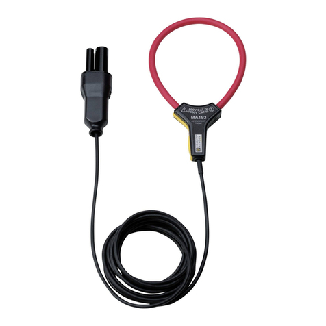
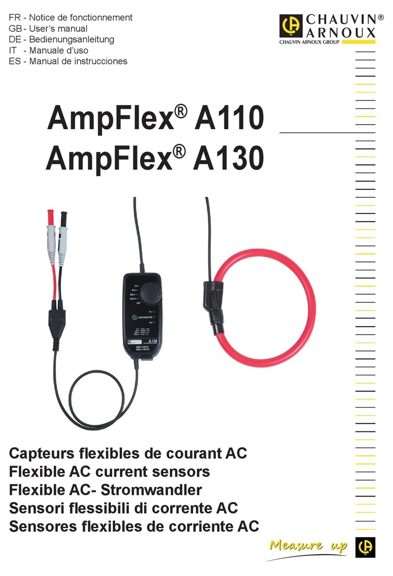
Chauvin Arnoux AmpFlex A100 User manual

AmpFlex®A100
OL
ON
10 mV/A
1 mV/A
300 - 3000A~/3 V~
600V CAT III
OFF
AC CURRENT PROBE
A 100
Office: Jl. Radin Inten II No. 62 Duren Sawit, Jakarta 13440 - Indonesia
Workshop: Jl. Pahlawan Revolusi No. 22B, Jakarta 13430 - Indonesia
Phone: 021-8690 6777 (Hunting) Fax: 021-8690 6771
Mobile: +62 816 1740 8925
Office: Jl. Radin Inten II No. 62 Duren Sawit, Jakarta 13440 - Indonesia
Workshop: Jl. Pahlawan Revolusi No. 22B, Jakarta 13430 - Indonesia
Phone: 021-8690 6777 (Hunting) Fax: 021-8690 6771
Mobile: +62 816 1740 8925

11
Thank you for purchasing an AmpFlex®A100 exible current sensor.
For best results from your instrument:
read these operating instructions carefully,
comply with the precautions for use.
WARNING, risk of DANGER! The operator must refer to these instructions whenever this
danger symbol appears.
WARNING, risk of electric shock. The voltage applied to parts marked with this symbol may
be hazardous.
Application or withdrawal authorized on conductors carrying dangerous voltages. Type B current
sensor as per IEC 61010-2-032.
Equipment protected by double insulation.
The CE marking indicates conformity with European directives, in particular LVD and EMC.
The rubbish bin with a line through it indicates that, in the European Union, the product must
undergo selective disposal in compliance with Directive WEEE 2002/96/EC.
Denition of measurement categories:
Measurement category IV corresponds to measurements taken at the source of low-voltage
installations.
Example: power feeders, counters and protection devices.
Measurement category III corresponds to measurements on building installations.
Example: distribution panel, circuit-breakers, machines or xed industrial devices
Measurement category II corresponds to measurements taken on circuits directly connected to low-
voltage installations.
Example: power supply to electro-domestic devices and portable tools.

12
PRECAUTIONS FOR USE
Comply with the rated maximum voltage and current and the measurement category.
Never exceed the protection limits stated in the specications.
Comply with the conditions of use, that is to say temperature, humidity, altitude, degree of pollution
and location of use.
Do not use the instrument if it is open, damaged, or incorrectly reassembled. Before each use, check
the integrity of the insulation on the coil, the leads, and the electronic unit.
The application or withdrawal of the sensor on uninsulated conductors at dangerous voltages requires
the use of suitable safety equipment.
If it is not possible to power down the installation, follow safe operating procedures and use suitable
means of protection.
All troubleshooting and metrological checks must be done by competent, accredited personnel.
CONTENTS
1. PRESENTATION................................................................................................................. 13
1.1. Standard models in a A100 series ........................................................................... 13
1.2. Custom models ........................................................................................................ 13
2. DESCRIPTION.................................................................................................................... 14
3. USE ................................................................................................................................. 14
4. SPECIFICATIONS............................................................................................................... 15
4.1. Reference conditions ............................................................................................... 15
4.2. Conditions of use ..................................................................................................... 15
4.3. power supply ........................................................................................................... 16
4.4. Measurement parameters ....................................................................................... 16
4.5. Compliance with electrical standards ...................................................................... 17
5. MAINTENANCE.................................................................................................................. 18
5.1. Battery replacement ................................................................................................ 18
5.2. Cleaning .................................................................................................................. 18
5.3. Calibration checking ................................................................................................ 18
5.4. Repair ...................................................................................................................... 18
6. WARRANTY ....................................................................................................................... 19
7. TO ORDER.......................................................................................................................... 19

13
1. PRESENTATION
1.1. STANDARD MODELS IN A A100 SERIES
A100 Series AmpFlex® sensors make up a range of nine standard models which enable the measurement
of alternating current from 0.5 A to 10 kA at industrial frequencies. Each probe is of a exible air-core
type (45 cm, 80 cm or 120 cm) attached by a shielded cable to a small box housing the integrator circuit
and a standard 9 V battery.
Their exibility means that they can be attached to any type of conductor for measurement (including
cables, busbars and stranded conductors), regardless of its accessibility. Because of the latch-type design
of the air-core’s open/close mechanism, it is appropriate to use gloves when operating it.
The box is tted with a two-position switch (single range) or a three-position switch (dual range) and two
LED diodes. One indicates that the device is in use (green LED), and the other warns when the integrator
circuit is overloaded (red LED).
Probes can be connected to any multimeter, tester, recorder, etc. tted with an alternating voltage input
with an impedance over 1 MW (AC mode without a DC component). They have reinforced insulation and
comply with international standards, particularly IEC 61010-1.
9 standard models
Range Lenght*
2 kA single range 45 cm
2 kA single range 80 cm
20 A / 200 A dual range 45 cm
200 A / 2 kA dual range 45 cm
200 A / 2 kA dual range 80 cm
300 A / 3 kA dual range 45 cm
300 A / 3 kA dual range 80 cm
300 A / 3 kA dual range 1.20 m
1 kA / 10 kA dual range 1.20 m
* 45 cm air core are preshaped.
1.2. CUSTOM MODELS
Probes of different length or sensitivity (mV/A) are available upon request. Custom lengths can be supplied
in 10 cm increments: contact us for more information.

14
2. DESCRIPTION
See illustration on p 50
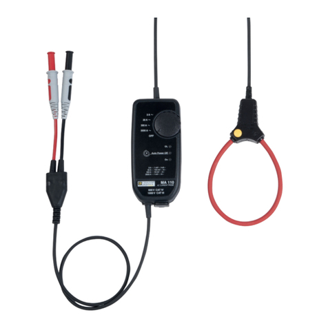
a Air core
Lenght 45 cm 80 cm 120 cm
Weight < 120 g < 240 g < 360 g
b Latch device
c Cable: 2 m lenght
d Box: dimensions 140 x 64 x 28 mm - weight 200 g
e Sliding switch with two positions (single range) or three positions (dual range)
f Green «ON» LED
- Continuous display when battery charge is sufcient
- Flashes when under eight hours of charge remain
g Red «OL» LED
- Displays when the measured current overloads the integrator circuit
h Output: two Ø 4 mm male safety plugs - 19 mm between centres
3. USE
Do not attach the probe to bare conductors carrying a dangerously high voltage unless wearing
protective clothing suitable for high-voltage work and using appropriate equipment for personal
protection.
The probe is not for use on cables or conductors with a potential of over 1000 V relative to earth.
Illumination of the red LED indicates an overload of the integrator circuit.
If the green LED fails to light, or flashes, the battery requires replacement. It begins
to ash when around 8 hours of battery life remain.
Open the exible air-core, and attach it to the conductor to be measured.
Close the air-core using the latching system.
Centring the conductor and making the air-core as circular as possible will ensure optimum
measurement accuracy.
Connect the box to a multimeter with V AC or mV AC ranges and with an impedance of over 1 MW.
Set the switch on the box to the desired range.
Read off the measurement by applying the ratio indicated by the switch position on the box
(see Chapter 4.4).

15
4. SPECIFICATIONS
4.1. REFERENCE CONDITIONS
Temperature: +18 ... +28°C
Relative humidity: 20 ... 75 % HR
Battery voltage: 9 V ± 0.5 V
Measurement of sinusoidal alternating current: 10 Hz to 100 Hz
Continuous magnetic eld: Earth’s magnetic eld (< 40 A/m)
Alternating external magnetic eld: none present
External electrical eld: none present
Position of conductor for measurement: centred within the air-core
Shape of air-core: practically circular
Impedance of multimeter connected: ≥ 1 MW
4.2. CONDITIONS OF USE
The box must be used within the following parameters to ensure user safety and measurement
accuracy:
Environmental conditions: see graph below
1 = Reference range 2 = Operational range 3 = Storage range
NB: the exible air-core can withstand a maximum temperature of 90°C.
Performance in humidity: 90% RH at 50°C.
Humidity %Hr
Temperature in °C
-50 -40 -30 -20 -10 0 10 20 30 40 50 60 70 80 90
90
100
80
70
60
50
40
30
20
10
0
3 2 1

16
4.3. POWER SUPPLY
9V alkaline battery (of type 6LF22)
Normal operational voltage: between 9 V and 7 V
Battery life:
- continuous operation: 150 hours
- intermittent use: 10,000 1-minute measurements
Battery low indicator: green “ON” LED ashes
4.4. MEASUREMENT PARAMETERS
Single/dual range
20 A
200 A
200 A
2 kA
300 A 1 kA
3 kA
100 mV/A
10
mV/A
10 mV/A 10 mV/A 1 mV/A
1
mV/A
1
mV/A
0.1
mV/A
1
mV/A
2 kA 10 kA
50 mV
5 mV
5 mV
2 mV
4 mV 2 mV
2 mV
2 mV 1 mV
Output/input ratio
(in mV-/A-)
°3.0°5.0°1
Operating use
Typical accuracy (1)
0.5 A ... 200 A~ 0.5 A ... 2 kA~ 0.5 A ... 2 kA~ 0.5 A ... 3 kA~
0.5 A ... 10 kA~
1%
4.5 V
600 V eff (crest factor 1.5)
Specified measurement
range (1)
5 A ... 200 A~ 5 A ... 2 kA~ 5 A ... 2 kA~ 5 A ... 3 kA~ 5 A ... 10 kA~
Pass band (2)
Typical phase
shift at 50 Hz
5.45.152.2
Crest factor
at nominal I
10 Hz to 20 kHz
0.2 A 0.5 A
Residual current
or noise (I=0)
Max. offset DC
voltage at output
Max. peak voltage
at output
Output impedance
Permissible overload
at output
9 standard models
Probe length (3)
20 - 200 A 2 kA 0,2 - 2 kA 0.3 - 3 kA 1 - 10 kA
45 cm 45 cm 80 cm 45 cm 80 cm 45 cm 80 cm 1.2 m 1.2 m
(1) See APPENDIX for linear graphs from 0.5 A up to 100 A
(2) See APPENDIX for frequency response graphs.
(3) The minimum radius of curvature is 15 mm

17
4.5. COMPLIANCE WITH ELECTRICAL STANDARDS
4.5.1 ELECTRICAL SAFETY IN LINE WITH IEC 61010-1 (IEC 61010-031, IEC 61010-2-032)
Double insulation
Installation category III
Operating voltage: 1000 V
Pollution level 2
4.5.2 ELECTROMAGNETIC COMPATIBILITY
Emissions and immunity in an industrial environment per IEC 61326-1.
- Electrostatic discharge (meets EN 61000-4-2)
8 kV in air - level 3 - class B
4 kV on contact - level 2 - class B
- 10V/m radiated electromagnetic eld (in line with EN 61000-4-3)
Class B
- Rapid transients (in line with EN 61000-4-4)
1 kV - level 2 - class B
- Electric shocks (in line with EN 61000-4-5)
6 kV - class B
4.5.3 MECHANICAL PROTECTION
Waterproong (in line with EN 60529)
- Box - protection index IP40
- Flexible probe : protection index IP40
Shocks: 100g (in line with IEC 68-2-27)
Drop test: 1m (in line with IEC 68-2-32)
Vibrations (in line with IEC 68-2-6)
4.5.4 AUTO-EXTINGUISHABILITY RATING
Flexible probe: V0 (in line with UL 94)
4.5.5 RESISTANCE TO CHEMICAL PRODUCTS
Flexible probe: resistant to oils and aliphatic hydrocarbons

5. MAINTENANCE
When performing maintenance, use only the specified replacement parts. The
manufacturer cannot be held responsible for any accident occurring subsequent to
repair work carried out by parties other than its own after-sales service team or agreed
repair personnel.
5.1. BATTERY REPLACEMENT
The battery must be replaced when the green LED ashes or fails to light up when the box is used.
Remove the exible probe from the circuit to be measured.
Set the box switch to ‚OFF‘
Disconnect the box from the measurement device.
Unscrew the two fastening screws on the box.
Replace the used battery with a 9V alkaline battery (type 6LF22)
Close the box again, retting the two screws.
5.2. CLEANING
The air-core and its latching system require no special care. Simply ensure that no foreign body is
allowed to obstruct the latching mechanism.
Clean the box with a cloth slightly dampened in soapy water. Clean off with a damp cloth.
Dry immediately afterwards with a cloth or with blown air at 80°C maximum.
5.3. CALIBRATION CHECKING
Like all measuring or testing devices, the instrument must be checked regularly.
This instrument should be checked at least once a year. For checking and calibration, contact one of our
accredited metrology laboratories (information and contact details available on request), at our Chauvin
Arnoux subsidiary or the branch in your country.
5.4. REPAIR
For all repairs before or after expiry of warranty, please return the device to your distributor.
Office: Jl. Radin Inten II No. 62 Duren Sawit, Jakarta 13440 - Indonesia
Workshop: Jl. Pahlawan Revolusi No. 22B, Jakarta 13430 - Indonesia
Phone: 021-8690 6777 (Hunting) Fax: 021-8690 6771
Mobile: +62 816 1740 8925
Table of contents
Other Chauvin Arnoux Accessories manuals

Chauvin Arnoux
Chauvin Arnoux MiniFlex MA110 User manual

Chauvin Arnoux
Chauvin Arnoux MN93 User manual

Chauvin Arnoux
Chauvin Arnoux MiniFLEX User manual

Chauvin Arnoux
Chauvin Arnoux MiniFlex MA110 User manual

Chauvin Arnoux
Chauvin Arnoux MN93 User manual

Chauvin Arnoux
Chauvin Arnoux AmpFlex A110 User manual

Chauvin Arnoux
Chauvin Arnoux MN93 User manual
Popular Accessories manuals by other brands

GLD Products
GLD Products Tucson MMXI manual

Ibanez
Ibanez AEL Series AEL10E instruction manual

PCB Piezotronics
PCB Piezotronics 333B30 Installation and operating manual

Dover
Dover PSG MOUVEX HYDRIVE 2010A Safety, storage, operation and maitenance instructions

NeuLog
NeuLog NUL-220 Guide

Apogee
Apogee SQ-618 owner's manual