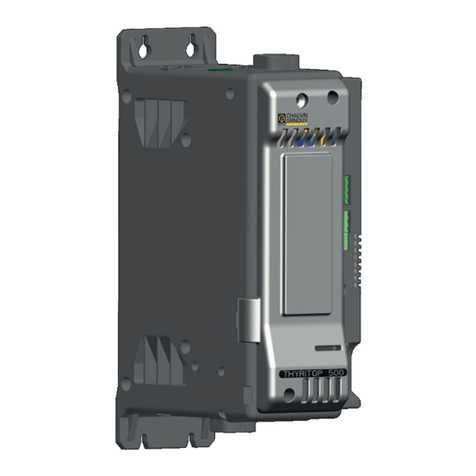
Chauvin Arnoux THYRITOP 600 Series User manual

40 to 600 A
power controllers
THYRITOP
SERIE
GB - Installation and operation manual

906121687 «THYRITOP 600»_05-2021_GB_page 1
Table of Contents ..................................................... 1
Preface ...................................................................... 3
Device data and initial checks..........................................................3
Warnings and safety.........................................................................3
Disposal............................................................................................3
Typographical conventions used in the manual ...............................4
Liability disclaimer............................................................................4
Copyright..........................................................................................4
1. General Description ......................................... 5
1.1. Summary................................................................................5
1.1.1. Profile ...........................................................................5
1.1.2. Control functions..........................................................5
1.1.3. Diagnostics, preventive maintenance and alarms .......5
1.1.4. Configuration ...............................................................6
1.1.5. Fieldbus .......................................................................6
1.1.6. More.............................................................................6
1.2. Field of use.............................................................................6
1.3. Technicians and operators .....................................................6
1.4. Thyritop 600 ...........................................................................7
1.4.1. Main elements of the Thyritop 600, 40 A ... 300 A....... 7
1.4.2. Main elements of the Thyritop 600, 400 A ... 600 A
models .........................................................................8
1.5. Rotary switches...................................................................... 8
1.6. Configuration dip switches ....................................................9
1.6.1. Type of load connection...............................................9
1.6.2. Initialisation procedure and loading of default values..9
1.7. LED indicator functions........................................................10
1.8. Dimensions...........................................................................11
1.8.1. Dimensions of Thyritop 600, 40 A ... 300 A models...11
1.8.2. Dimensions of Thyritop 600, 400 A ... 600 A .............12
2. Installation and power supply .......................14
2.1. Installing the controller......................................................... 14
2.1.1. General installation rules............................................14
2.1.2. Positioning and minimum ventilation space .............. 14
2.1.3. Fixing to the electrical panel ......................................14
2.2. Power supply .......................................................................16
2.3. EMC and LVD conformity.....................................................16
2.3.1. EMC conformity .........................................................16
2.3.2. EMC filters..................................................................16
2.3.3. LVD or low voltage conformity ................................... 16
2.3.4. Electrical safety..........................................................16
2.5. Thyritop 600 insulation diagram...........................................18
3. Electrical connections ...................................19
3.1. Description of the connections ............................................19
3.2. Inputs ...................................................................................21
3.2.1. J3 connector - Power supply and digital inputs. .......21
3.2.2. J4 Connector - Analogue control inputs.................... 22
3.2.3. J5 connector - External CT inputs (optional) .............23
3.3. Outputs ................................................................................24
3.3.1. J1 connector - outputs 5...8 (optional).......................24
3.3.1.1. Optional D-type outputs (digital) .......................24
3.3.1.2. Optional outputs type W (analogue) ..................25
3.3.1.3. Optional outputs type R (relays) ........................25
3.3.2. J2 connector - outputs 9 and 10 (relay type)............. 25
3.4. Serial communication port ...................................................26
3.4.1. Location of the ports..................................................26
3.4.2. PORT1 (local bus): Modbus serial interface -
connectors J8 and J9 ................................................27
3.4.3. PORT2 (optional Fieldbus) type M: Modbus RTU /
Modbus RTU - connectors S4, S5............................. 27
TABLE OF CONTENTS
3.4.4. PORT2 (optional Fieldbus) type P: Modbus RTU /
Profibus DP - connectors S4, S5............................... 28
3.4.5. PORT2 (optional Fieldbus) type C: Modbus RTU /
CANopen - connectors S4, S5 ..................................29
3.4.6. PORT2 (optional Fieldbus) type E: Modbus RTU /
Ethernet Modbus TCP - connectors S4, S5 ..............30
3.4.7. PORT2 (optional Fieldbus) type E6 / E7 / E8 -
connectors S4, S5 .....................................................31
3.5. Power connections .............................................................. 32
3.5.1. Recommended cable cross-section with Thyritop 600
40 A ... 300 A .............................................................32
3.5.2. Recommended cable cross-section with Thyritop 600
400 A ... 600 A ...........................................................33
3.6. Connection examples - Power section for Thyritop 600 40
A...Thyritop 600 300 A .........................................................35
3.6.1. Connection example for single-phase Thyritop 600
(1PH) for a single-phase load.....................................35
3.6.2. Connection example for single-phase Thyritop 600
(1PH) for a single-phase load with transformer .........36
3.6.3. Connection example for single-phase Thyritop 600
(1PH) control option 4 for single-phase load with
transformer ................................................................37
3.6.4. Connection example for two-phase Thyritop 600 (2PH)
for 2 independent single-phase loads .......................38
3.6.5. Connection example for two-phase Thyritop 600 (2PH)
for a three-phase star load without neutral................39
3.6.6. Connection example for two-phase Thyritop 600 (2PH)
for a three-phase star load without neutral with trans-
former.........................................................................40
3.6.7. Connection example for two-phase Thyritop 600 (2PH)
control option 4 for a three-phase star load without
neutral with transformer............................................. 41
3.6.8. Connection example for two-phase Thyritop 600 (2PH)
for a three-phase closed delta load ...........................42
3.6.9. Connection example for two-phase Thyritop 600 (2PH)
for a three-phase closed delta load with transformer 43
3.6.10. Connection example for two-phase Thyritop 600 (2PH)
control option 4 for a closed delta load with
transformer.................................................................44
3.6.11. Connection example for three-phase Thyritop 600
(3PH) for 3 independent single-phase loads..............45
3.6.12. Connection example for three-phase Thyritop 600
(3PH) for a three-phase star load with neutral ........... 46
3.6.13. Connection example for three-phase Thyritop 600
(3PH) for a three-phase star load without neutral......47
3.6.14. Connection example for three-phase Thyritop 600
(3PH) for a three-phase star load without neutral with
transformer.................................................................48
3.6.15. Connection example for three-phase Thyritop 600
(3PH) control option 4 for a three-phase star load
without neutral with transformer ................................ 49
3.6.16. Connection example for three-phase Thyritop 600
(3PH) for three-phase closed delta load ....................50
3.6.17. Connection example for three-phase Thyritop 600
(3PH) for a three-phase closed delta load with trans-
former.........................................................................51
3.6.18. Connection example for three-phase Thyritop 600
(3PH) control option 4 for three-phase closed delta
load with transformer .................................................52
3.6.19. Connection example for three-phase Thyritop 600
(3PH) for three-phase open delta load.......................53
3.6.20. Connection example for three-phase Thyritop 600
(3PH) for 3 independent loads in open delta ............. 54
3.7. Connection examples - Power section for Thyritop 600 400 A
...600 A .................................................................................55
3.7.1. Connection example for single-phase Thyritop 600
(1PH) for a single-phase load.....................................55
3.7.2. Connection example for single-phase Thyritop 600
(1PH) for a single-phase load with transformer .........56
3.7.3. Connection example for two-phase Thyritop 600 (2PH)
for 2 independent single-phase loads .......................57

3.7.4. Connection example for two-phase Thyritop 600 (2PH)
for a three-phase star load without neutral................58
3.7.5. Connection example for two-phase Thyritop 600 (2PH)
for a three-phase star load without neutral with trans-
former.........................................................................59
3.7.6. Connection example for two-phase Thyritop 600 (2PH)
for a three-phase closed delta load ...........................61
3.7.7. Connection example for two-phase Thyritop 600 (2PH)
for a three-phase closed delta load with transformer 62
3.7.8. Connection example for three-phase Thyritop 600
(3PH) for 3 independent single-phase loads..............64
3.7.9. Connection example for three-phase Thyritop 600
(3PH) for a three-phase star load with neutral ........... 65
3.7.10. Connection example for three-phase Thyritop 600
(3PH) for a three-phase star load without neutral......66
3.7.11. Connection example for three-phase Thyritop 600
(3PH) for a three-phase star load without neutral with
transformer.................................................................67
3.7.12. Connection example for three-phase Thyritop 600
(3PH) for three-phase closed delta load ....................69
3.7.13. Connection example for three-phase Thyritop 600
(3PH) for a three-phase closed delta load with trans-
former.........................................................................70
3.7.14. Connection example for three-phase Thyritop 600
(3PH) for three-phase open delta load.......................72
3.7.15. Connection example for three-phase Thyritop 600
(3PH) for 3 independent loads in open delta ............. 73
3.8. Notes on use with inductive loads and transformers...........74
4. Operating modes............................................75
4.1. Trigger modes ......................................................................75
4.1.1. “Zero crossing” mode................................................75
4.1.1.1. ZC - constant cycle time ...................................75
4.1.1.2. BF - variable cycle time .....................................75
4.1.1.3. HSC - Half single cycle......................................76
4.1.2. Phase angle (PA) ........................................................76
4.2. Additional functions ............................................................. 77
4.2.1. Softstart .....................................................................77
4.2.2. RMS current limit .......................................................77
4.2.3. DT - Delay triggering.................................................. 78
4.3. Digital input (PWM)...............................................................79
5. Using Port 1 “Modbus RTU”..........................80
5.3.1. “AutoBaud Port 1” procedure.................................... 80
6. Maintenance ...................................................81
6.1. Periodic cleaning..................................................................81
6.1.1. Overtemperature alarm .............................................. 81
6.2. Replacing the internal fuse................................................... 82
6.3. Replacing the fieldbus interface board ................................ 84
6.4. Disposal ...............................................................................84
7. Technical specifications ................................85
7.1. Derating curves ....................................................................92
8. Order codes ....................................................93
9. Accessories ....................................................94
9.1. Kit, keypad and cables......................................................... 95
9.2. Ultrarapid fuses.................................................................... 95
9.3. Short-circuit protection / SCCR ...........................................96

906121687 «THYRITOP 600»_05-2021_GB_page 3
PREFACE
Device data and initial checks
Write down the order code and other plate data displayed
on the label on the outside of the controller (see illustration)
here. Should you require technical assistance, this informa-
tion must be given to Pyrocontrole Customer Service.
Check also that the product is intact and has not been
damaged during transport, and that the packaging contains
the Instructions for Use and Warnings in addition to the
product.
Serial number SN
Finished product
code CODE
Order code TYPE
Rated voltage and
rated current SUPPLY
Firmware version VERS.
Warnings and safety
This document supplements the following manuals:
• Thyritop 600 Configuration and Programming Manual,
“Thyritop 600 (last update).pdf.
Always make sure you have the latest version of the man-
ual, which can be downloaded freely from the Pyrocontrole
website (www.pyrocontrole.com).
The devices described in the manual must be installed by
qualified technicians, following current laws and regula-
tions and in accordance with the instructions given in this
manual.
Installation and/or maintenance technicians must read this
manual and carefully follow the instructions given here and
in the annexes as Pyrocontrole cannot be held liable for
damage to persons, property and/or the product through
failure to comply with the following conditions.
This manual must be available to the people who interact
with the devices described here.
Before interacting with the Thyritop 600 power controller,
the operator must be sufficiently trained in the operation,
emergency, diagnostics and maintenance procedures for
the devices.
If the Thyritop 600 power controllers are used in applica-
tions with risk of damage to persons, machines or mate-
rials, they must be combined with auxiliary alarm devices.
It is advisable to provide the possibility of checking alarm
activation also during normal operation.
Do not touch the terminals on the device when it is pow-
ered.
In the event of suspected instrument malfunctions, before
contacting the Pyrocontrole Technical Service, it is advisa-
ble to read the Troubleshooting Guide in the “Maintenance”
section and the F.A.Q. (Frequently Asked Questions) section
on the Pyrocontrole website www.pyrocontrole.com.
Disposal
The instrument must be segregated from other
waste at the end of its useful life.
The user must take the equipment at the end of
its useful life to an appropriate sorting centre for
electrotechnical and electronic waste, or a similar
facility, in accordance with the regulations in force
in the country of installation, in order to dispose of
the components which are potentially harmful to
the environment.
This helps prevent negative effects on the envi-
ronment and health and facilitates recycling of the
materials from which the instrument is made.
Any inconsistencies, missing items or obvious signs of
damage must be reported immediately to your Pyrocontrole
dealer.
Check that the order code corresponds to the configuration
required for the intended use of the controller, by consulting
chapter “8. Order codes”.
TYPE:
PXXXXXX
Open Type Equipment
Installation Category II
SCCR RMS SYM
100KA / 600V
CPU SUPPLY:
CODE:
TH600-xPH-xxx-xxx-0-0-x-x-x-x-x
LOAD SUPPLY:
24Vdc ±10% xxVA max
xxxVac 50/60Hz xxxA max
RoHS
®US
LISTED
C
E243386
SN:
XXXXXXXX
FW:
X.XX.XX
FIELDBUS TYPE:
xx-xxxxxxxxxxxx
FIELDBUS FW:
X.XX
PYROCONTROLE - CHAUVIN ARNOUX GROUP
6 Bis Av Docteur Schweitzer
69881 MEYZIEU Cedex
FRANCE

906121687 «THYRITOP 600»_05-2021_GB_page 4
Typographical conventions used in the manual
Pay attention when the following symbols are found in the manual.
This indicates particularly important information
relevant to correct product operation or safety, or
provide instructions that must be strictly followed.
This indicates a risk condition for the installation
technician or user due to hazardous voltages.
This calls the reader’s attention to a specific point.
This indicates a suggestion that could be helpful
for better use of the device.
This indicates a reference to other technical docu-
ments that may be downloaded from
www.pyrocontrole.com.
WWW
Liability disclaimer
Copyright
Although all information contained within this document
has been carefully checked, Pyrocontrole cannot be held
liable for the possible presence of errors, or for damage to
persons or property due to improper use of this manual.
Pyrocontrole also reserves the right to make changes to the
content and form of this document and to the features of
the devices it describes at any time without prior notice.
The technical and performance data given in this manual
are to be considered as a guide for the user to determine
the suitability for a certain use and are not a guarantee.
They may be the result of Pyrocontrole test conditions and
the user must compare them to his/her real application
requirements.
Pyrocontrole cannot be held in any way liable for damage
to persons or property resulting from tampering or use that
is incorrect, improper or otherwise incompliant with the
features of the controller and the instructions contained in
this manual.
Pyrocontrole shall not be liable for installations upstream or
downstream from the instrument.
This document and its annexes may be freely reproduced,
provided that the contents are not modified in any way
and each copy includes this warning and the statement of
Pyrocontrole ownership.
Pyrocontrole and Pyrotools are trademarks of Pyrocontrole.
The document may mention or reproduce trademarks and
logos of third parties. Pyrocontrole acknowledges the rights
over these trademarks or logos of their respective owners.

906121687 «THYRITOP 600»_05-2021_GB_page 5
1. GENERAL DESCRIPTION
1.1. Summary
1.1.1. Profile
The Advanced Power Controllers of the Thyritop 600 series
are self-contained units with the capability of controlling
high electrical power levels for various types of sin-
gle-phase, two-phase and three-phase heating elements.
The controllers allow great flexibility of use in all current and
voltage ratings, from 40 A to 600 A and at nominal voltages
of 480 Vac, 600 Vac and 690 Vac.
They are ideal for accurate, stable temperature control in
industrial heating systems.
Their advanced load control functions allow the manage-
ment of linear resistors with a low thermal coefficient,
non-linear resistors with a high thermal coefficient, infrared
lamps, and single-phase and three-phase symmetrical and
asymmetrical transformers.
Compact mechanics, together with ease of wiring with front
connections and plug-in connectors and easy configuration
methods ensure considerable savings in terms of panel
space and installation time, without sacrificing robustness
and a notable diagnostic capacity.
1.1.2. Control functions
All Thyritop 600 models can be operated in different modes
to adapt to the various control solutions and architectures
found in the field.
The three analogue inputs are highly configurable, so that
both two-phase and three-phase devices can be controlled
with a single command, and each available module can be
controlled individually and independently.
Thyritop 600s can also be operated with digital ON/OFF
controls or in PWM mode, through potentiometers, using
one of the various Fieldbuses that complete the options of
this range.
Flexibility in the control of electrical loads, even very dif-
ferent from each other, is guaranteed by a vast choice of
trigger types, freely configurable on all models.
There is a choice of “Zero Crossing” (ZC) mode with fixed
cycle times or “Burst Firing” (BF) mode with optimised
cycle times, for linear loads and systems with high thermal
inertia.
There is also the option of faster firing modes, such as
“Half Single Cycle” (HSC), which is ideal for handling mid-
wave IR lamps, and of “phase angle” (PA) control, for SWIR
lamps, non-linear heating elements such as silicon carbide,
silicon molybdenum and both single and three-phase trans-
former primaries.
Whichever control configuration is chosen, Thyritop 600
models are able to deliver the desired electrical power, from
0% to 100%, with precision.
The following functions complete the control:
• softstart at power-on,
• current limits settable on both peak values and RMS
values,
• closed-loop feedback algorithms for voltage, current
and power, which guarantee supply stability even in
the presence of variations and disturbances in rated
values.
Some functions of the Thyritop 600 range are designed for
specific applications and problems:
• For systems with three-phase transformers, any
breakages of three-phase load branches are man-
aged by the controller, which provides an immediate
alarm signal while continuing to supply energy to the
two intact phases, allowing the process to remain in a
holding condition.
• In heat treatments with non-linear resistors, such as
silicon carbide, heating elements can be brought up to
temperature with “phase angle” control and active cur-
rent limits, with automatic switching to “zero crossing”
control when the elements are at temperature and there
are no more current peaks, returning to “phase angle”
control automatically only if further peaks reoccur.
• Three-phase transformers are very often used in in-
dustrial furnaces, with symmetrical or asymmetrical
primary/secondary connections. Thyritop 600 control-
lers can manage both types indiscriminately without
any impact on performance.
• Auxiliary voltage (V load) and current (external CT)
inputs allow proper management of all applications
where cable length and transformer type require pre-
cise voltage and current measurement exactly on
the load, regardless of other plant engineering factors.
• In the case of several loads managed by different con-
trollers, there is a need to rationalise and synchronise
the power outputs of the individual controllers so
as to reduce peaks of current/energy supplied instantly
or, in some cases, limit the total value to a settable
maximum. These functions are performed by a special
external controller, the Pyro-ALM, capable of managing
up to 64 controllers and configurable via VNC.
1.1.3. Diagnostics, preventive
maintenance and alarms
Great care has been taken in the development of diagnos-
tic, preventive maintenance and alarm functions that can
be associated with current, voltage and power values and
operating temperatures. The process and power controller
are continuously monitored.
For current values:
• Total or partial interrupted load alarm with alarm
threshold teach-in.
• SCR short circuit alarm.
• Short circuit or surge load alarm.
• Internal fuse breakage alarm.
For voltage values:
• No line voltage alarm.
• Unbalanced three-phase line alarm.
• Indication of incorrect phase rotation in three-phase
systems (without interruption of controller operation)

906121687 «THYRITOP 600»_05-2021_GB_page 6
For temperature values:
• Exclusive continuous temperature measurement of
all power terminals with an alarm for loose terminal
diagnosis.
• Continuous monitoring of the internal temperature of
the power module with automatic disconnection and
an alarm signal in the event of over-temperature.
• Fan output temperature measurement for electrical
panel cooling system efficiency diagnostics.
• Insufficient fan power alarm.
The Pyrotools configuration software also offers an exten-
sive list of additional diagnostic conditions, such as alarm
status storage, for immediate and easy analysis in the event
of a fault.
1.1.4. Configuration
The Thyritop 600 controllers have been designed with var-
ious configuration levels to make initial start-up operations
as simple and intuitive as possible.
The Pyrotools configuration software (freely downloadable
from the Pyrocontrole site www.pyrocontrole.com) has a
“Smart Configuration” procedure to configure the control-
ler through a few targeted questions, with limited need for
knowledge of the parameters and their meanings. At the
end of the procedure (average duration 5 minutes) the con-
troller is ready to pilot the load.
Another section of the software contains the “Wizard” pag-
es, showing the main parameters divided into topics, with a
part of the parameter monitoring always active.
With Pyrotools, you can create and save entire parameter
recipes and easily duplicate them on other devices. Param-
eters can also be monitored and displayed graphically with
the oscilloscope function.
The Thyritop 600 controllers can be equipped with a Tyritop
remote portable programming terminal, powered by the
controller, which permits monitoring of process variables
and changes of configurations, if necessary, via password.
1.1.5. Fieldbus
A Modbus RTU port is always available for connections
with the configuration tool or with HMI or PLC devices
equipped with Modbus Master communication.
An extensive range of certified Fieldbus options lets you
add Thyritop 600 controllers to control architectures with
the most popular PLC brands, allowing you to access any
device variable with standardised configuration files.
These controls can be combined with softstart ramp
functions, with options such as “current limit” to manage
current peaks at switch-on and the RMS current value at
steady state, thus optimising consumption and increasing
the operating life of the load.
1.1.6. More
The availability of phase angle (PA) control (the only control
method that completely eliminates flickering in IR lamps),
combined with current limit and current, voltage or load
power feedback functions, means that “critical” applica-
tions such as Super-Kanthal™ special heating elements, sil-
icon carbide resistors or single and three phase transformer
primaries can be resolved with confidence.
1.2. Field of use
1.3. Technicians and operators
As the Advanced Power Controller can be used in a multi-
tude of installations and environments, adequate technical
training is required to make full use of the instrument’s
potential.
In any event, the instrument must always be used within the
limits indicated in the technical specifications in the accom-
panying documentation.
Regardless of any other consideration, it is always strictly
forbidden to:
• use the instrument or parts of it (including software) for
purposes other than those intended in the accompany-
ing technical documentation;
The Advanced Power Controller must only be used by per-
sonnel qualified for their assigned task, in compliance with
the instructions for the task, particularly the relevant safety
warnings and precautions.
Qualified personnel, due to their training and experience,
are able to recognise the risks involved in use of the instru-
ment and avoid potential hazards.
• modify working parameters not accessible to the
operator, or decrypt or transfer the software or any of
its parts;
• use the instrument in particularly flammable environ-
ments;
• repair or modify the instrument using non-original spare
parts;
• use the instrument or its parts without having read and
correctly interpreted the contents of the accompanying
technical documentation;
• dispose of or discard the instrument in common land-
fills.
In addition, it is assumed that the technicians who commis-
sion the instrument and connect it to other units, and those
in charge of maintenance, have adequate technical knowl-
edge, particularly in the field of electronics and automation,
to fully understand the information provided in this manual.

906121687 «THYRITOP 600»_05-2021_GB_page 7
1.4. Thyritop 600
Main features
• Single/two/three-phase, 40 A to 600 A
• Operating voltages 480 Vac, 600 Vac and 690 Vac
• Firing mode configurable to “Zero crossing” (Fixed Cy-
cle, Burst Firing, Half Single Cycle) and “Phase angle”
• Analogue control inputs configurable to Volt, mA, po-
tentiometer and digital “PWM”
• Three settable retransmission analogue outputs
• Optional inputs from external CTs and VTs
• Softstart and RMS and peak current limits
• V, V 2, I, I2and P feedback
• Total and partial interrupted load alarms with relay
outputs
• Built-in fuses
• Temperature sensors on power terminals and cooling
air inlet
• Fieldbus: PROFINET, Profibus, Modbus TCP/RTU,
Ethernet IP, EtherCAT and CANopen
• Configuration keypad and monitor
• PC configuration tool with setup wizard (SMART)
• • CE, UL, CSA certifications and SCCR UL 508 100KA
approvals
1.4.1. Main elements of the Thyritop 600, 40 A ... 300 A
1. Auxiliary output connector
2. Relay output connector
3. Power supply connector and 24 V digital inputs
4. Dip switch configuration
5. Rotary switches (addressing)
6. Connector with 3 analogue inputs
7. Thyritop 600-OP keypad connector
8. Load terminal (pre-split protection grid)
9. Protective cover on internal fuse and line/load
connections
10. Line terminal (pre-split protection grid)
11. V-load measurement connector
12. V-line measurement connector
13. 3-way external CT input connector
14. Port2 Fieldbus connectors and LED
15. Operating status LED
16. Port1 RS 485 Modbus RTU
Figure 1 - Elements of the Thyritop 600 40 A ... 300 A models
1
2
3
10 13
11
9
14
15
16
12
4
5
6
7
8

906121687 «THYRITOP 600»_05-2021_GB_page 8
1. Auxiliary output connector
2. Relay output connector
3. Power supply connector and 24 V digital inputs
4. Dip switch configuration
5. Rotary switches (addressing)
6. Connector with 3 analogue inputs
7. Thyritop 600-OP keypad connector
8. 24 V fan power supply output connector
9. Load terminal (pre-split protection grid)
10. Protective cover on internal fuse and line/load connec-
tions
11. Line terminal (pre-split protection grid)
12. V-load measurement connector
13. V-line measurement connector
14. 3-way external CT input connector
15. Port2 Fieldbus connectors and LED
16. Operating status LED
17. Port1 RS 485 Modbus RTU
Figure 2 - Elements of the Thyritop 600 400 A ... 600 A models
The two hexadecimal rotary switches are used
to set the address of the module. Available
addresses range from 00...99; hexadecimal com-
binations are reserved.
The tens selector is identified by x10 and the
units selector by x1.
x10
x1
In multi-node operation mode (configuration DIP switch
7 = ON), the selected address is assigned to the Thyritop
600 module only and the expansions, if present, have the
following addresses:
Thyritop 600-E1 = address Thyritop 600 + 1
Thyritop 600-E2 = address Thyritop 600 + 2
1.4.2. Main elements of the Thyritop 600, 400 A ... 600 A models
1.5. Rotary switches
1
2
3
4
5
6
7
8
9
10 11
12
13
14
15
16
17

906121687 «THYRITOP 600»_05-2021_GB_page 9
1.6. Configuration dip switches
The DIP switches are used to set the configura-
tion of the Advanced Power Controller.
The functions associated with the DIP switches
are:
• DIP switches 1 to 5: configuration of the type of load
connection and presence of a transformer. See para-
graph “1.6.1. Type of load connection” for DIP switch
settings.
1234
567
ON
• DIP switch 6: loading of the default values for the
configuration selected with DIP switches 1 to 7. See
paragraph “1.6.2. Initialisation procedure and loading
of default values” for the sequence of operations to be
carried out.
• DIP switch 7: multi-node addressing enabled, if ON.
1.6.2. Initialisation procedure and load-
ing of default values
IMPORTANT! After setting the desired configura-
tion with the DIP switches, perform the following
initialisation procedure once.
With the device switched off:
1. Check that DIP switches 1-2-3-4-5-7 are set correctly.
2. Set DIP switch 6 to ON.
3. Power the device with 24 VDC.
4. Wait for the green LED (RUN) to flash regularly.
5. Set DIP switch 6 to OFF.
The configuration is correctly activated.
1.6.1. Type of load connection
The table shows the settings of DIP switches 1...5 depending on the load to be controlled.
DIP 1 DIP 2 DIP 3 DIP 4 DIP 5 * Type of load connection
HW configuration
TH600-
1PH
TH600-
2PH
TH600-
3PH
OFF OFF OFF OFF OFF/ON
1 single-phase load ■■■
2 single-phase loads ■ ■
3 single-phase loads ■
OFF ON OFF OFF OFF 3 independent single-phase open delta
loads ■
ON ON OFF OFF OFF Three-phase open delta load ■
Three-phase star load with neutral ■
ON ON ON OFF OFF/ON Three-phase closed delta load ■
ON OFF OFF ON OFF/ON Three-phase star load without neutral ■
ON OFF OFF OFF OFF/ON Three-phase star load without neutral
with TWO-PHASE control ■
ON OFF ON OFF OFF/ON Three-phase closed delta load with TWO-
PHASE control ■
DIP 5 * : OFF = Resistive Load
ON = Inductive load (transformer)

906121687 «THYRITOP 600»_05-2021_GB_page 10
1.7. LED indicator functions
LED Colour Description
RN green Run: flashing during regular operation
ER red Error status: activated in the presence of an alarm
DI1 yellow Digital input 1 status
DI2 yellow Digital input 2 status
O1 yellow Out 1 Master module (M) power output status
O2 yellow Out 2 expansion 1 (E1) power output status, managed only with Thyritop 600 versions 2PH and 3PH
O3 yellow Out 3 expansion 2 (E2) power output status, managed only with Thyritop 600 version 3PH
BUTTON yellow HB button status
During normal operation, the status of the LEDs follows the corresponding parameter.
In the following special cases they assume different behaviours to indicate the following states:
LED Behaviour Description
RN On steadily HB button pressed
RN + ER Flashing together Autobaud in progress
ER Flashing
Reports one or more of the following alarms:
• OVER_ HEAT temperature alarm
• TEMPERATURE_SENSOR_BROKEN temperature alarm
• SHORT_CIRCUIT_CURRENT alarm
• SSR_SAFETY alarm
• FUSE_OPEN alarm
• INTERLOCK function active (Input DI4 set to OFF)
ER + Ox Flashing together Indicate that the HB or POWER_FAULT alarm is active on module x.
All except
DI1 Flashing rapidly Jumper configuration not provided
All except
DI2 Flashing rapidly 30%_UNBALANCED_ ERROR alarm (only in three-phase configuration)
All except
O1 Flash rapidly SHORT_CIRCUIT_CURRENT alarm (only in three-phase configuration)
All except
O2 Flashing rapidly TRIPHASE_MISSING_LINE_ERROR alarm (only in three-phase configuration)
All except
O3 Flashing rapidly SSR_SAFETY or HW_OVER_HEAT alarm (only in three-phase configuration)
All except
BUTTON Flashing rapidly FUSE_OPEN alarm (only in three-phase configuration)

906121687 «THYRITOP 600»_05-2021_GB_page 11
186
302
287
42
137
42
84
170
87 87 87
258171
224
302
339
350
312 196
87 87 87
180
Lorem ipsum
1.8.1. Dimensions of Thyritop 600, 40 A ... 300 A models
Single-phase
All dimensions in mm
Side view with keypad Side view without keypad
Figure 3 - Dimensions of Thyritop 600 40 ... 300 A (single-phase)
1.8. Dimensions
Figure 4 - Dimensions of Thyritop 600 40 ... 300 A (two- and three-phase)
Two-phase and Three-phase
All dimensions in mm

906121687 «THYRITOP 600»_05-2021_GB_page 12
65
297
145
350
339
286
65
65 65 190
240
339
350
65 65
1.8.2. Dimensions of Thyritop 600, 400 A ... 600 A
Figure 5 - Dimensions of Thyritop 600 400 ... 600 A (single-phase)
Single-phase
All dimensions in mm
Figure 6 - Dimensions of Thyritop 600 400 ... 600 A (two-phase)
Two-phase
All dimensions in mm

906121687 «THYRITOP 600»_05-2021_GB_page 13
65 65 65
65 65 65
285
339
339
335
Figure 7 - Dimensions of Thyritop 600 400 ... 600 A (three-phase)
(Three-phase)
All dimensions in mm

906121687 «THYRITOP 600»_05-2021_GB_page 14
2. INSTALLATION AND POWER SUPPLY
Caution! The installation of the devices described
in this manual must be carried out by qualified
technicians, following current laws and regulations
and in accordance with the instructions given in
this manual.
Before installation, check that the controller is
intact and has not been damaged during trans-
port. Also ensure that the package contains all the
accessories listed in the documentation.
Check that the order code corresponds to the
configuration required for the intended use of the
controller (rated supply voltage and current, num-
ber and type of inputs and outputs). See chapter
“8. Order codes” to check the configuration for
each order code.
2.1. Installing the controller
2.1.1. General installation rules
The Thyritop 600 Advanced Power Controller is designed
for permanent indoor installation. It must be installed in
electrical panels or in the control panels of machines or
production process systems, where the exposed terminals
will be protected.
Caution! The Advanced Power Controller must
NOT be installed in hazardous environments (flam-
mable or explosive atmospheres). It may only be
connected to elements operating in such environ-
ments by means of suitable types of interfaces, in
conformity with the applicable safety standards.
Caution! If the Advanced Power Controller is used
in applications with risk of damage to persons
or property, it must be used in conjunction with
dedicated alarm devices. We recommend allowing
the possibility to check alarm operation also during
normal operation of the controller and the system
or equipment being monitored.
The Advanced Power Controller must not be installed
where sudden changes in temperature, freezing or conden-
sation can occur or where corrosive gases are present.
The Advanced Power Controller can operate in environ-
ments with a pollution degree 2 rating.
Caution! Unless adequately protected, the pro-
tection rating of the Advanced Power Controller is
IP20.
2.1.2. Positioning and minimum
ventilation space
To ensure the high reliability of the device, it is essential to
install it properly inside the electrical panel so as to ensure
an adequate exchange of heat.
Mount the device vertically (maximum 10° inclination from
the vertical plane).
The temperature of the compartment containing the Con-
troller must not exceed 50°C for models with rated current
from 400 A to 600 A and 40°C for models with rated current
from 40 A to 300 A (for higher temperatures, see the derat-
ing curves).
Never obstruct the ventilation grills.
Ensure the minimum clearance for adequate air circulation:
• Vertical distance between a device and the panel wall
>100 mm
• Horizontal distance between a device and the panel
wall at least 10 mm
• Vertical distance between one device and another at
least 300 mm.
• Horizontal distance between one device and another at
least 10 mm.
See “Figure 8 - Thyritop 600 minimum ventilation spaces”.
Ensure that these distances are not reduced by cable duct-
ing. If necessary, mount the units away from the panel wall
so that the air can flow vertically without obstruction.
2.1.3. Fixing to the electrical panel
The fixing to the electrical panel is made via the slots at the
top and bottom of the controller.
Use M5 screws or bolts or equivalent.
The following illustrations show the drilling templates to be
used for fixing the controller, depending on the model and
configuration (single-phase, two-phase or three-phase).
All measurements are in mm.
Caution! If even one of the above-mentioned
requirements (qualified technician, device intact,
configuration compatible with needs) is not met,
suspend installation and contact your Pyrocontrole
dealer or Pyrocontrole Customer Service.

906121687 «THYRITOP 600»_05-2021_GB_page 15
> 100 mm > 100 mm
> 10 mm > 10 mm
42
287.4
6.6
8
21 75
87.2 95
5.2
5.2
338.2
338.2
87.2 87.2 95
6
6
42 42
15.8 65 65
31.5
6515.8
5.2
5.2
339
339
65 65 6565
31.5
65
31.5
6515.8
6
6
5.2
339
6
Figure 8 - Thyritop 600 minimum ventilation spaces
Figure 9 - Thyritop 600 drilling templates
Cold zone
Air deflector
Outgoing air
flow
Incoming air
flow
Hot zone
Single-phase (1 PH)
4 holes
4 holes 8 holes
4 holes
12 holes
6 holes
Two-phase (2 PH) Three-phase (3 PH)
Thyritop 600 40 ...
300 A
Thyritop 600 400 ...
600 A

906121687 «THYRITOP 600»_05-2021_GB_page 16
2.2. Power supply
2.3. EMC and LVD conformity
The Advanced Power Controller is NOT supplied with an
ON/OFF switch.
It is the responsibility of the user to provide a switch or
disconnector compliant with the applicable safety re-
quirements (CE marking) to disconnect the power supply
upstream of the controller.
The switch, or disconnector, must be placed in the imme-
diate vicinity of the device and be easily accessible to the
operator.
A single switch can be used for several controllers.
The Advanced Power Controller must be supplied by a sep-
arate line to that used for electromechanical power devices
(relays, contactors, solenoid valves, etc.).
Caution! The supply must come from a Class II or
limited power source.
Suitable mains filters should be used in the vicinity of
high-frequency generators or arc welding machines.
A voltage stabiliser should be used if there are large varia-
tions in the mains voltage.
Ensure that the earth connection is efficient and made via
a specific conductor. A missing or ineffective earth connec-
tion can cause unstable device operation due to excessive
environmental disturbances.
In particular, check that:
• the voltage between neutral and earth is ≤ 1 V;
• the ohmic resistance is < 6 Ω.
It is advisable to mount a ferrite core on the supply line, as
close to the controller as possible, to limit electromagnetic
interference.
The power supply line must be separate from the control-
ler’s inputs and outputs.
2.3.1. EMC conformity
The Advanced Power Controller meets the electromagnetic
compatibility requirements of Directive 2014/30/EU and
subsequent amendments.
EMC conformity has been verified with regard to the infor-
mation given in Tables 1 and 2.
The Thyritop 600 series of products are mainly intended for
use in an industrial environment, installed in switchboards
or control panels of machines or production process sys-
tems.
The strictest general standards have been applied for elec-
tromagnetic compatibility purposes, as shown in the tables
below.
Caution! The controller is designed for class A
equipment. Use in a domestic environment may
cause radio interference. In this case, the user
may be required to adopt additional attenuation
methods.
2.3.2. EMC filters
EMC filters are required in PA (Phase Angle, i.e., SCR trig-
gering with a modulated phase angle) operating mode.
The filter model and current size depend on the configura-
tion and the load used. It is important that the power filter is
connected as close as possible to the Thyritop 600.
A filter connected between the power supply line and the
Thyritop 600 or an LC unit connected between the Thyritop
600 output and the load may be used.
2.3.3. LVD or low voltage conformity
The Thyritop 600 complies with the Low Voltage Directive
2014/35/EU.
2.3.4. Electrical safety
See table 3 for the standards applied.

906121687 «THYRITOP 600»_05-2021_GB_page 17
EMC emission:
AC semiconductor motor controllers and conductors for
non-motor loads EN 60947-4-3
Emission enclosure compliant in firing mode single cycle and
phase angle if external filter fitted
EN 60947-4-3
CISPR-11
EN 55011
Class A Group 2
Table 1
EMC Immunity
Generic standards, immunity standard for industrial environ-
ments EN 60947-4-3
ESD immunity EN 61000-4-2 4 kV contact discharge
8 kV air discharge
RF interference immunity EN 61000-4-3 /A1
10 V/m amplitude modulat-
ed 80 MHz-1 GHz
10 V/m amplitude modulat-
ed 1.4 GHz-2 GHz
Conducted disturbance immunity EN 61000-4-6 10 V/m amplitude modulat-
ed 0.15 MHz-80 MHz
Burst immunity EN 61000-4-4 2 kV power line
1 kV I/O signal line
Surge immunity EN 61000-4-4/5
Power line - line 1 kV
Power line - earth 2 kV
Signal line - earth 2 kV
Signal line - line 1 kV
Magnetic fields immunity
Test is not required.
Immunity is demonstrat-
ed by the successfully
completion of the operating
capability test.
Voltage dips, short interruptions and voltage immunity tests EN 61000-4-11 100%U, 70%U, 40%U,
Table 2
Electrical safety
Safety requirements for electrical equipment for
measurement, control and laboratory use EN 61010-1/A1
UL Standard for Safety Industrial Control Equipment UL 508
Table 3

906121687 «THYRITOP 600»_05-2021_GB_page 18
2.4. Thyritop 600 insulation diagram
POWER SUPPLY
CPU
INPUTS
PORT 1 PORT 2
CT INPUTS (I_load)
CT1, CT2, CT3
4 KV
Main Processor
EEprom
RAM
LEDs
OUTPUTS
max 230 Vac
1 KV
500 V
Fieldbus MODBUS RS485
Ethernet modbus TCP
Ethernet-IP
Ethercat
CANopen
Profibus
1 KV
Supply 18 …32 V
Modbus RS-485
1 KV
ANALOGUE CONTROL INPUTS
DIGITAL INPUTS
DI1, DI2, DI3, DI4
VT INPUTS (V_line)
TV1, TV2, TV3
OUT
5,6,7,8,
Analogue / Digital
max 690 Vac SSR
SSR1, SSR2, SSR3
POWER CONTROL
OUT 1,2,3
4 KV
2 KV
±5 V
1 KV DC / DC
5 V
1 KV DC / DC
Parts connected to 24 V low
voltage
Live parts
5 V (PORT1)
Parts connected to high
voltage (90...690 V)
Live parts
5 V CPU
Legend
OUT 9, 10 RELAY

906121687 «THYRITOP 600»_05-2021_GB_page 19
COM
OUT5
OUT6
OUT 7
OUT 8
C (OUT 9)
NC
NO
C (OUT10)
NC
NO
+24 Vdc SUPPLY
GND
EARTH
+ INDIG 1
+ INDIG 2
+ INDIG 3
+ INDIG 4
GND
ETH0
ETH1
E01
E02
E11
E12
RUN.....................
ERROR.................
DI1.......................
DI2.......................
01........................
02........................
03........................
BUTTON...............
J4
J3
J2
J1
OUT +5 V
+INA1
GND
EARTH
+INA2
+INA3
GND
J8-J9
J4
J3
J2
J1
TA1 +
TA1 -
TA2 +
TA2 -
TA3 +
TA3 -
J5
(Ref. V_LOAD)
J10
4 / T2
(Ref. V_LOAD)
4 / T2
(Ref. V_LINE)
3 / L2
J10
5 / T3
(Ref. V_LINE)
3 / L2
3. ELECTRICAL CONNECTIONS
3.1. Description of the connections
Figure 10 - Description of the Thyritop 600 40 A...Thyritop 600 300 A connections
Description of the Thyritop 600 40 A...
Thyritop 600 300 A connections
CAUTION! Before connecting or disconnecting any connections, check that the power, power supply and con-
trol cables are isolated from voltage. External circuits connected must have double insulation. The input cables
must be physically separated from those of the power supply, outputs and power connections. Use braided and
shielded cables for the inputs, with the sheathing earthed at a single point. Appropriate fuses or automatic circuit
breakers must always be provided to protect the power lines. The fuses in the module serve only to protect the
semiconductors of the Thyritop 600.
TOP VIEW
J5
Connector (optional)
3 EXTERNAL CT inputs
LINE and LOAD reference voltage
connector
2 / T1
“LOAD” connection
1 / L1
“LINE” connection
DB9
KEYPAD connector
Auxiliary output connector
(optional)
Relay output connector
(OUT)-OUT10)
Power supply connector and 24
V digital inputs
PORT2
FIELD BUS + status LED
(optional)
Magnetic area for
fixing KEYPAD
Load configuration
DIP switch
HB Button
Potentiometer
MODBUS address
rotary switches
Analogue Input
connector
PORT1
RS-485 MODBUS RTU
2 RJ11 Connectors
Termination DIP switch
8 status LEDs
(configurable)
(green)
(red)
(yellow)
(yellow)
(yellow)
(yellow)
(yellow)
(yellow)
Fan grid
LINE and LOAD reference voltage
connector with control option 4.
FRONT VIEW
BOTTOM VIEW
This manual suits for next models
20
Table of contents
Other Chauvin Arnoux Controllers manuals
Popular Controllers manuals by other brands

Samson
Samson Trovis 5475-2 Mounting and operating instructions

Hitachi
Hitachi PC-ARFG2-M Installation & maintenance manual

Hanbay
Hanbay RD-AC Series user manual

Enttec
Enttec OCTO MK2 user manual

Mitsubishi
Mitsubishi MELSEC-AnS Series Handbook

Emerson
Emerson Bettis GVO LP DA Installation, operation and maintenance manual