Chauvin Arnox C.A 6165 User manual
C.A 6165
Appliance multitester
GB - Quick start guide

2
Contents
1General description....................................................................................................................................... 3
1.1 Warnings and notes ................................................................................................................................... 3
1.1.1 Safety warnings.....................................................................................................................................3
1.1.2 Warnings related to safety of measurement functions...........................................................................3
1.1.3 Markings on the instrument ...................................................................................................................4
2Instrument description ................................................................................................................................. 5
2.1 Front panel.................................................................................................................................................5
3Instrument operation .................................................................................................................................... 7
3.1 General meaning of keys ...........................................................................................................................7
3.2 General meaning of touch gestures: ..........................................................................................................7
3.3 Symbols and messages .............................................................................................................................8
4Single tests.................................................................................................................................................. 11
4.1 Single test measurements........................................................................................................................11
4.1.1 Visual inspections................................................................................................................................11
4.1.2 Continuity............................................................................................................................................. 12
4.1.3 HV AC ................................................................................................................................................. 15
4.1.4 HV DC ................................................................................................................................................. 16
4.1.5 HV AC programmable ......................................................................................................................... 18
4.1.6 HV DC programmable .........................................................................................................................19
4.1.7 Insulation resistance (Riso, Riso-S).....................................................................................................21
4.1.8 Sub-leakage (Isub, Isub-S).................................................................................................................. 23
4.1.9 Differential Leakage.............................................................................................................................25
4.1.10 Ipe Leakage.................................................................................................................................... 27
4.1.11 Touch Leakage............................................................................................................................... 29
4.1.12 Power.............................................................................................................................................. 30
4.1.13 Leak's & Power............................................................................................................................... 32
4.1.14 Discharging Time............................................................................................................................ 34
4.1.15 Functional inspections ....................................................................................................................37
5Maintenance ................................................................................................................................................ 39
5.1 Fuses ....................................................................................................................................................... 39
5.2 Warranty................................................................................................................................................... 39

3
1 General description
1.1 Warnings and notes
Read before use
1.1.1 Safety warnings
In order to reach high level of operator safety while carrying out various measurements using the C.A 6165 instrument,
as well as to keep the test equipment undamaged, it is necessary to consider the following general warnings:
Read this Instruction manual carefully, otherwise use of the instrument may be dangerous for the operator,
for the instrument or for the equipment under test!
Consider warning markings on the instrument!
If the test equipment is used in manner not specified in this Instruction manual the protection provided by the
equipment may be impaired!
Do not use the instrument and accessories if any damage is noticed!
Regularly check the instrument and accessories for correct functioning to avoid hazard that could occur from
misleading results.
Consider all generally known precautions in order to avoid risk of electric shock while dealing with hazardous
voltages!
Use only standard or optional test accessories supplied by your distributor!
Only test adapters provided or approved by Chauvin Arnoux should be connected to TC1 (test and
communication) connectors.
Use only earthed mains outlets to supply the instrument!
In case a fuse has blown refer to chapter 5.1 Fuses in this Instruction manual to replace it!
Instrument servicing and calibration is allowed to be carried out only by a competent authorized person!
Chauvin Arnoux is not responsible for the content of the user-programmed Auto Sequences®!
1.1.2 Warnings related to safety of measurement functions
1.1.2.1 HV AC, HV DC, HV AC programmable, HV DC programmable
A dangerous voltage up to 5 kVAC or 6 kVDC is applied to the HV instrument outputs during the test. Therefore
special safety consideration must be taken when performing this test!
Only a skilled person familiar with hazardous voltages can perform this measurement!
DO NOT perform this test if any damage or abnormality (test leads, instrument) is noted!
Never touch exposed probe tip, connections equipment under test or any other energized part during the
measurements. Make sure that NOBODY can contact them either!
4
DO NOT touch any part of test probe in front of the barrier (keep your fingers behind the finger guards on the
probe) – possible danger of electric shock!
It is a good practice to use lowest possible trip-out current.
1.1.2.2 Diff. Leakage, Ipe Leakage, Touch Leakage, Power, Leak’s & Power
Load currents higher than 10 A can result in high temperatures of fuse holders and On/Off switch! It is advisable
not to run tested devices with load currents above 10 A for more than 15 minutes. Recovery period for cooling is
required before proceeding with tests! Maximum intermittent duty cycle for measurements with load currents higher
than 10 A is 50 %.
1.1.2.3 Insulation resistance
Do not touch the test object during the measurement or before it is fully discharged! Risk of electric shock!
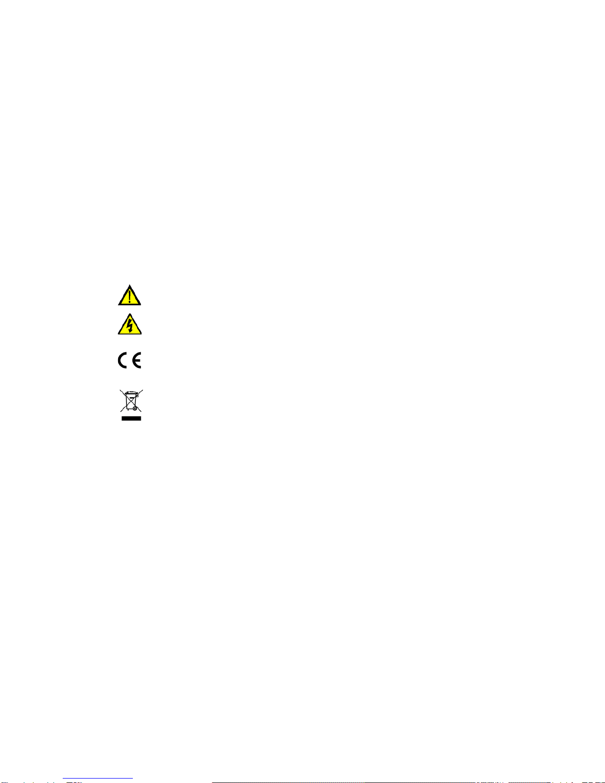
1.1.3 Markings on the instrument
Read the Instruction manual with special care to safety operation«. The symbol requires an action!
Dangerous high voltage is present on terminals during the test. Consider all precautions in order to
avoid risk of electric shock.
Mark on your equipment certifies that it meets European Union requirements for EMC, LVD, and
ROHS regulations.
This equipment should be recycled as electronic waste.

5
2 Instrument description
2.1 Front panel
Figure 2.1: Front panel
1
Mains supply connector
2
F1, F2 fuses (F 5 A / 250 V)
3
F3, F4 fuses (T 16 A / 250 V)
4
On / Off switch
5
Test connections TC1 for external test adapters
6
Mains test socket
7
P/S (probe) connector
8
Keypad
9
HV output connectors
10
HV output warning lamp
11
Continuity connectors
12
Insulation / Subleakage connectors
13
Discharging time connectors
14
Colour TFT display with touch screen
15
Control outputs
16
Control inputs
17
Multipurpose RS232-1 port
18
Multipurpose RS232-2 port
19
Ethernet connector
C.A 6165

6
20
USB connector
21
MicroSD card slot
7
3 Instrument operation
The C.A 6165 can be manipulated via a keypad or touch screen.
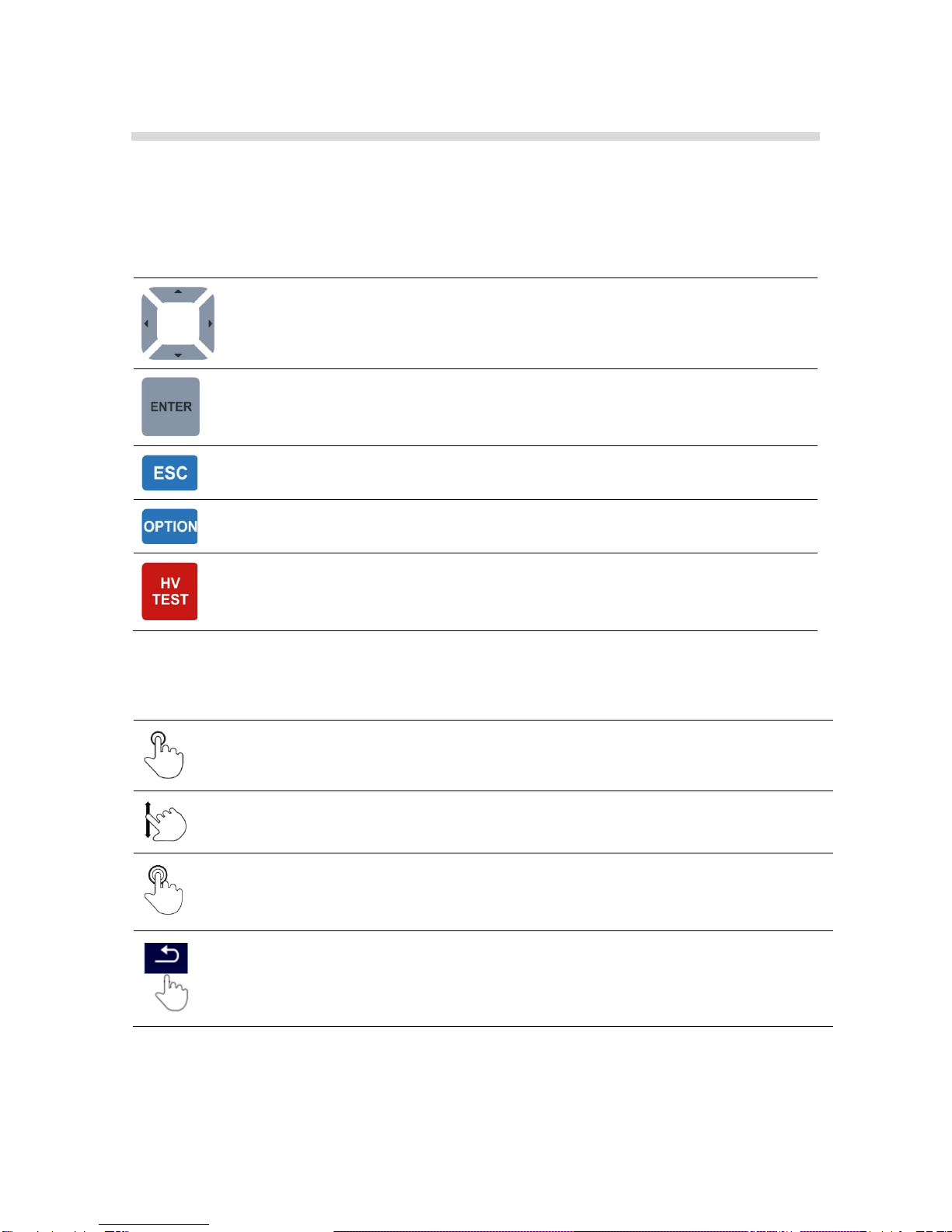
3.1 General meaning of keys
Cursor keys are used to:
- select appropriate option
Enter key is used to:
- confirm selected option
- start and stop measurements
Escape key is used to:
- return to previous menu without changes
- abort measurements
Option key is used to:
- expand column in control panel
- show detailed view of options
HV Test key is used to:
- start and stop HV tests
3.2 General meaning of touch gestures:
Tap (briefly touch surface with fingertip) is used to:
- select appropriate option
- confirm selected option
- start and stop measurements
Swipe (press, move, lift) up/ down is used to:
- scroll content in same level
- navigate between views in same level
long
Long press (touch surface with fingertip for at least 1 s) is used to:
- select additional keys (virtual keyboard)
- enter cross selector from single test screens
Tap Escape icon is used to:
- return to previous menu without changes
- abort measurements
8
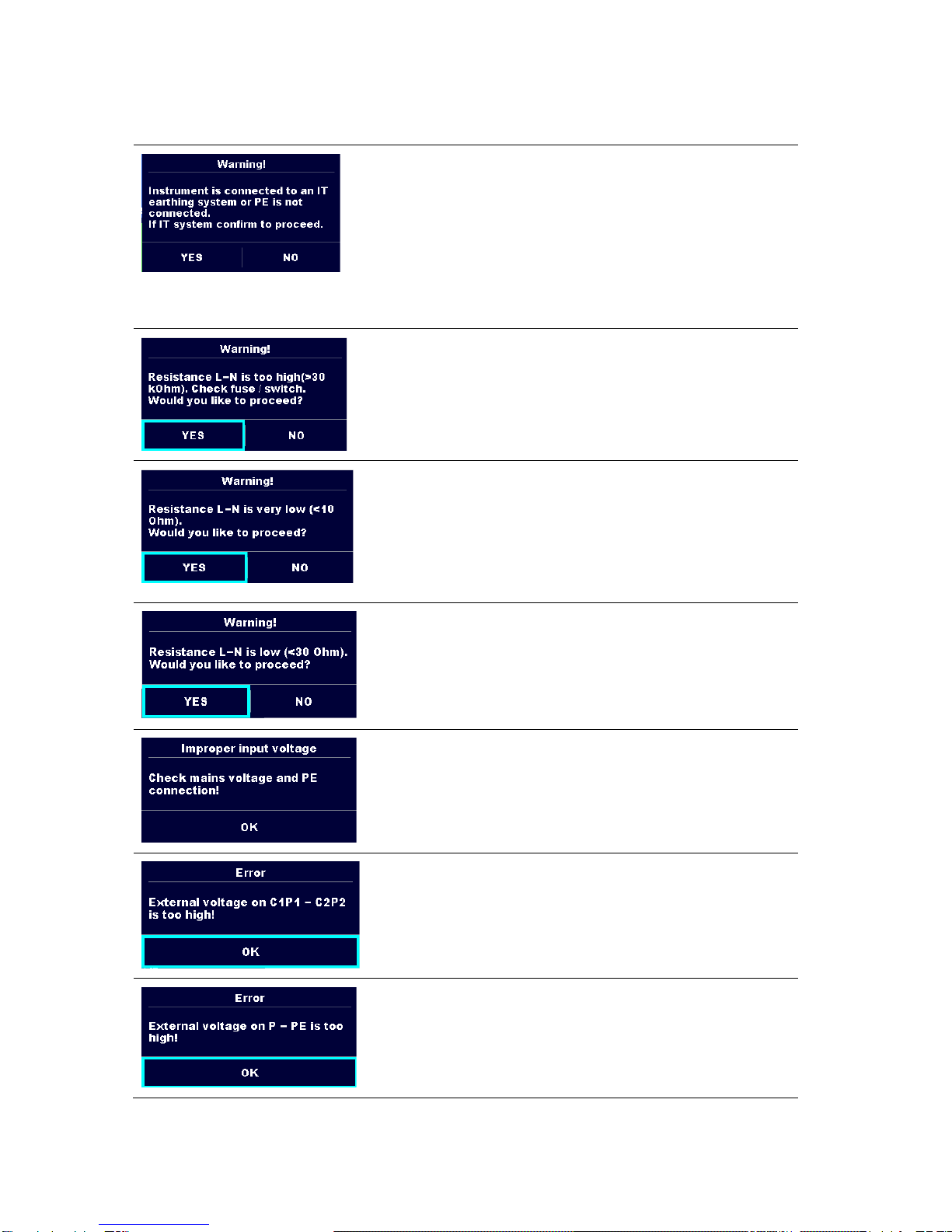
3.3 Symbols and messages
Supply voltage warning
Possible causes:
No earth connection.
Instrument is connected to an IT earthing system. Press
YES to continue normally or NO to continue in a limited
mode (measurements are disabled).
Warning:
The instrument must be earthed properly to work safely!
Resistance L-N > 30 kΩ
In pre-test a high input resistance was measured. Possible causes:
Device under test is not connected or switched on
Input fuse of device under test is blown.
Select YES to proceed with or NO to cancel measurement.
Resistance L-N < 10 Ω
In pre-test a very low resistance of the device under test supply input
was measured. This can result in a high current after applying power
to the device under test. If the too high current is only of short
duration (caused by a short inrush current) the test can be performed
otherwise not.
Select YES to proceed with or NO to cancel measurement
Resistance L-N < 30 Ω
In pre-test a low input resistance of the device under test was
measured. This can result in a high current after applying power to
the device. If the high current is only of short duration (caused by a
short inrush current) the test can be performed, otherwise not.
Select YES to proceed with or NO to cancel measurement.
Warning for improper supply voltage condition. If pressing OK
instrument will continue to work in a limited mode (measurements
are disabled).
In pre-test an external voltage between C1/P1 and C2/P2 terminals
was detected. The measurement was cancelled. Press OK to
continue.
In pre-test a too high external voltage was detected between P and
PE terminals. The measurement was cancelled. Press OK to
continue.
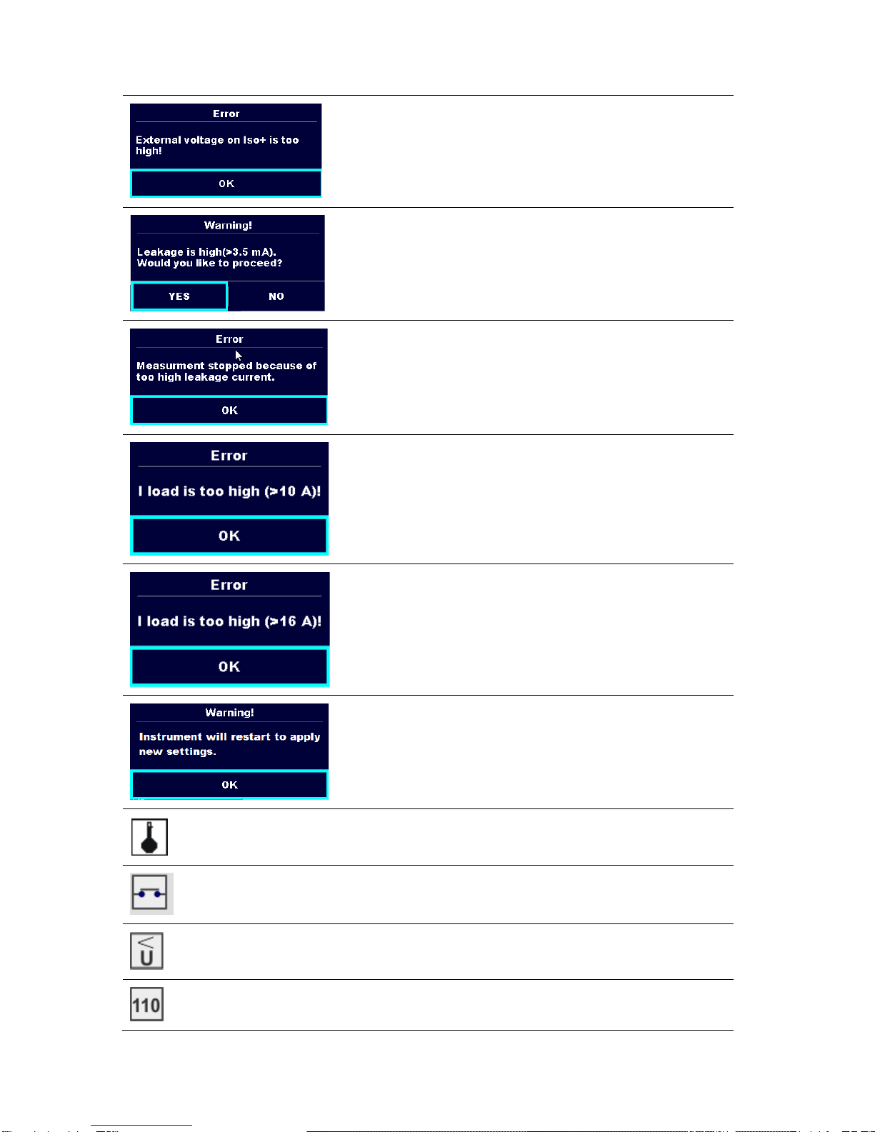
9
In pre-test a too high external voltage was detected between
ISO/SUB and PE terminals. The measurement was cancelled. Press
OK to continue.
In pre-test a possible high leakage current was detected. It is likely
that a dangerous leakage current (higher than 3.5 mA) will flow after
applying power to the device under test.
Select YES to proceed with or NO to cancel measurement.
The measured leakage (Idiff, Ipe, Itouch) current was higher than 20
mA. Measurement was aborted. Press OK to continue.
The load current exceeded the highest upper limit of 10 A for the
Discharging time test. Measurement was aborted. Press OK to
continue.
The load current continuously exceeded 10 A for more than 4 min
(moving average) in Power and Leakage tests. Measurement was
stopped for safety. Press OK to continue.
The load current exceeded the highest upper limit of 16 A for the
Power and Leakage tests. Measurement was aborted. Press OK to
continue.
Warning for restart of the instrument to set new Ethernet settings.
This message appears on exit from Settings menu after changing
Ethernet settings. Press OK to continue.
The instrument is overheated. The measurement can’t be carried out
until the icon disappears. Press OK to continue.
The device under test should be switched on (to ensure that the
complete circuit is tested).
Test voltage in Insulation resistance measurement is too low.
Measurement result is scaled to 110 V.
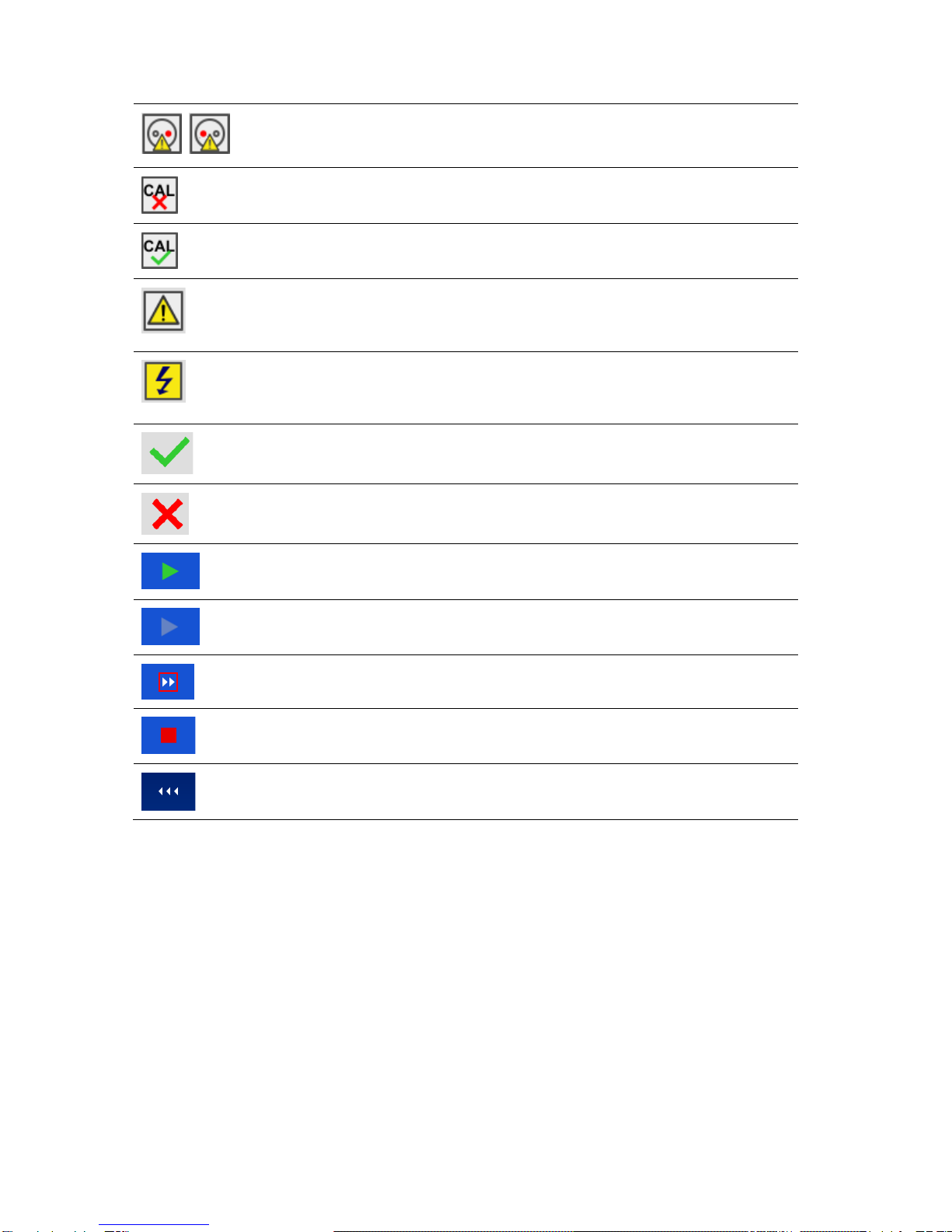
10
Red dot indicates phase of measurement where higher leakage was
measured. Applicable only if phase reversal is enabled during the
measurement.
Test leads resistance in Continuity P/S - PE measurement is not
compensated.
Test leads resistance in Continuity P/S - PE measurement is
compensated.
Warning!
A high voltage is / will be present on the instrument output!
(Withstanding test voltage, Insulation test voltage, or mains voltage).
Warning!
A very high and dangerous voltage is / will be present on the
instrument output! (Withstanding test voltage).
Test passed.
Test failed.
Conditions on the input terminals allow starting the measurement;
consider other displayed warnings and messages.
Conditions on the input terminals do not allow starting the
measurement, consider displayed warnings and messages.
Proceeds to next measurement step
Stop the measurement.
Expands column in control panel.

11
4 Single tests
4.1 Single test measurements
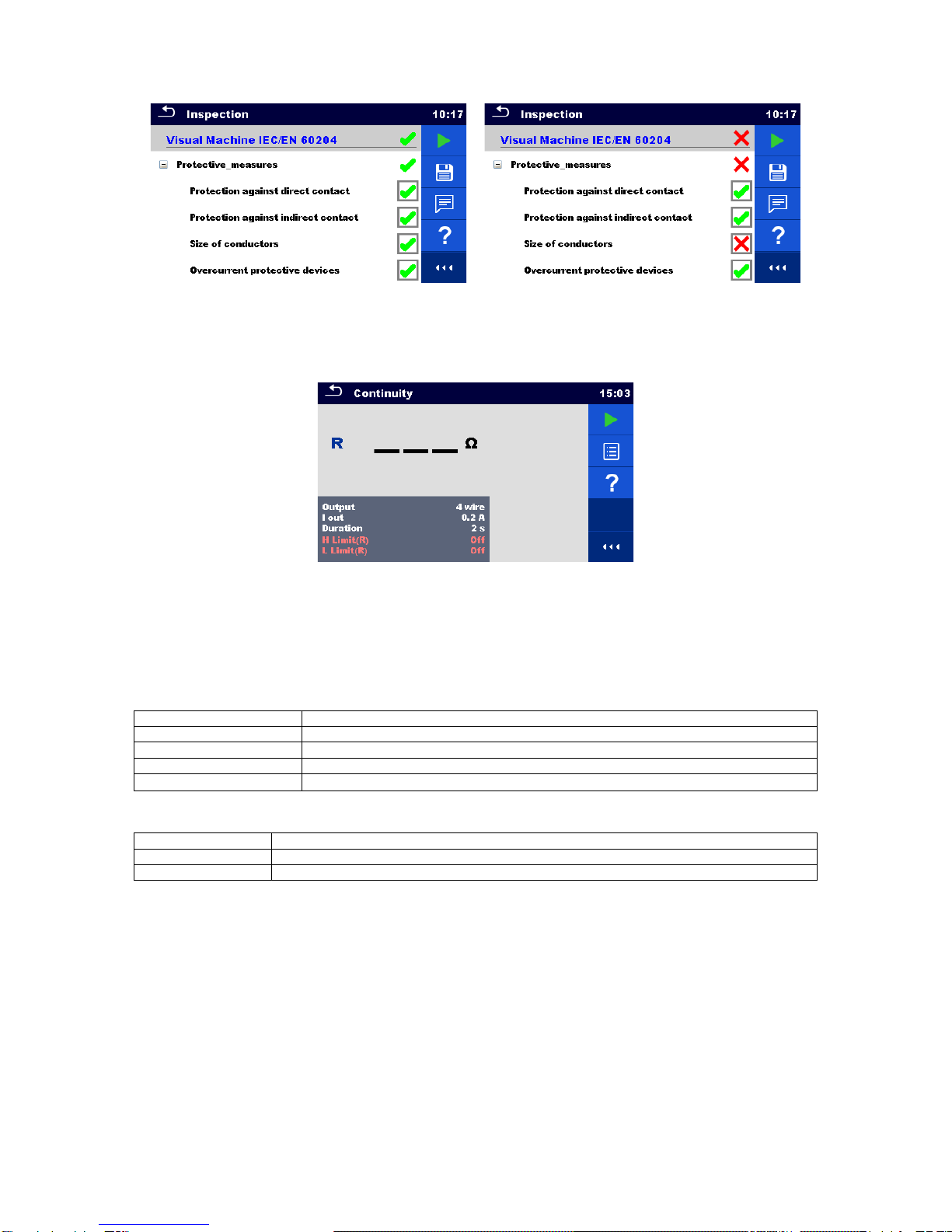
4.1.1 Visual inspections
Figure 4.1: Visual inspection menu
Test circuit
Figure 4.2: Visual inspection test circuit
Visual inspection procedure
Select the appropriate Visual inspection.
Start the inspection.
Perform the visual inspection of the appliance / equipment.
Apply appropriate ticker(s) to items of inspection.
End inspection.
Save results (optional).
12
Figure 4.3: Examples of Visual inspection results
4.1.2 Continuity
Figure 4.4: Continuity test menu
Test results / sub-results
R................... Resistance
ΔU………..Voltage drop scaled to 10 A
Test parameters
Output connections
Output [4-wire, P-PE]
Test current
I out [0.2 A, 4 A, 10 A, 25 A]
Duration
Duration [Off, 2 s ... 180 s]
ΔU test*
Enables ΔU test [On, Off]
Wire section*
Wire section for ΔU test [0.5 mm2…≥6mm2]
Test limits
H Limit (R)
H limit [Off, 0.01 Ω ... 9 Ω, Custom ]
L Limit (R)
L limit [Off, 0.01 Ω ... 9 Ω, Custom ]
H Limit (ΔU)*
H limit [1.0 V … 5.0 V ]
* Applicable only at test current 10 A.
13
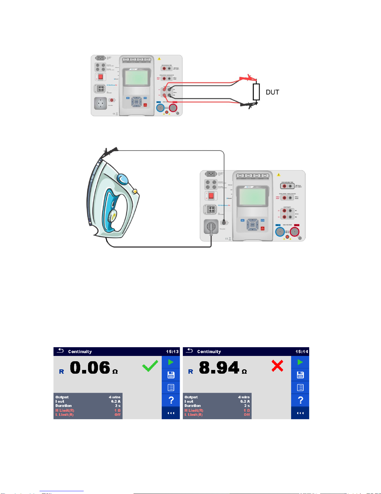
Test circuit
Figure 4.5: Measurement of continuity 4-wire
Figure 4.6: Measurement of Continuity P/S - PE
Continuity measurement procedure
Select the Continuity function.
Set test parameters / limits.
Connect test leads to C1, P1, P2 and C2 terminals on the instrument (4 wire), or connect test lead to P/S terminal
(2 wire measurement P/S – PE).
Compensate test leads resistance (optional).
Connect test leads to device under test.
Start measurement.
Measurement can be stopped manually or by timer.
Save results (optional).
Figure 4.7: Examples of Continuity measurement results

14
4.1.2.1 Compensation of test leads resistance
This chapter describes how to compensate the test leads resistance in Continuity (Output = P/S –PE) function.
Compensation can be carried out to eliminate the influence of test leads resistance and the internal resistances of the
instrument on the measured resistance.
Connection for compensating the resistance of test leads
Figure 4.8: Shorted test leads
Compensation of test leads resistance procedure
Select the Continuity function. Parameter Output must be set to P/S - PE.
Connect test leads to the instrument and short the test leads together, see Figure 4.8.
Touch the key to compensate leads resistance.
Symbol is displayed if the compensation was carried out successfully.
Figure 4.9: Uncompensated and compensated result
Note:
The compensation of test leads is carried out with set test current (I out).

15
4.1.3 HV AC
IMPORTANT SAFETY NOTE
Refer to chapter 1.1 Warnings and notes for more information regarding safe use of the instrument.
Figure 4.10: HV AC test menu
Test results / sub-results
I.................... test current
U................... measured a.c. test voltage
Ir................... resistive portion of test current
Ic .................. capacitive portion of test current
Test parameters
AC test voltage
U test [100 V ... 5000 V in steps of 10 V]
Duration
t end [Off, 1 s ... 120 s]
Test limits
High limit (I)
H limit [0.5 mA ... 100 mA ]
Low limit (I)
L limit [Off, 0.5 mA ... 100 mA]
Test circuit
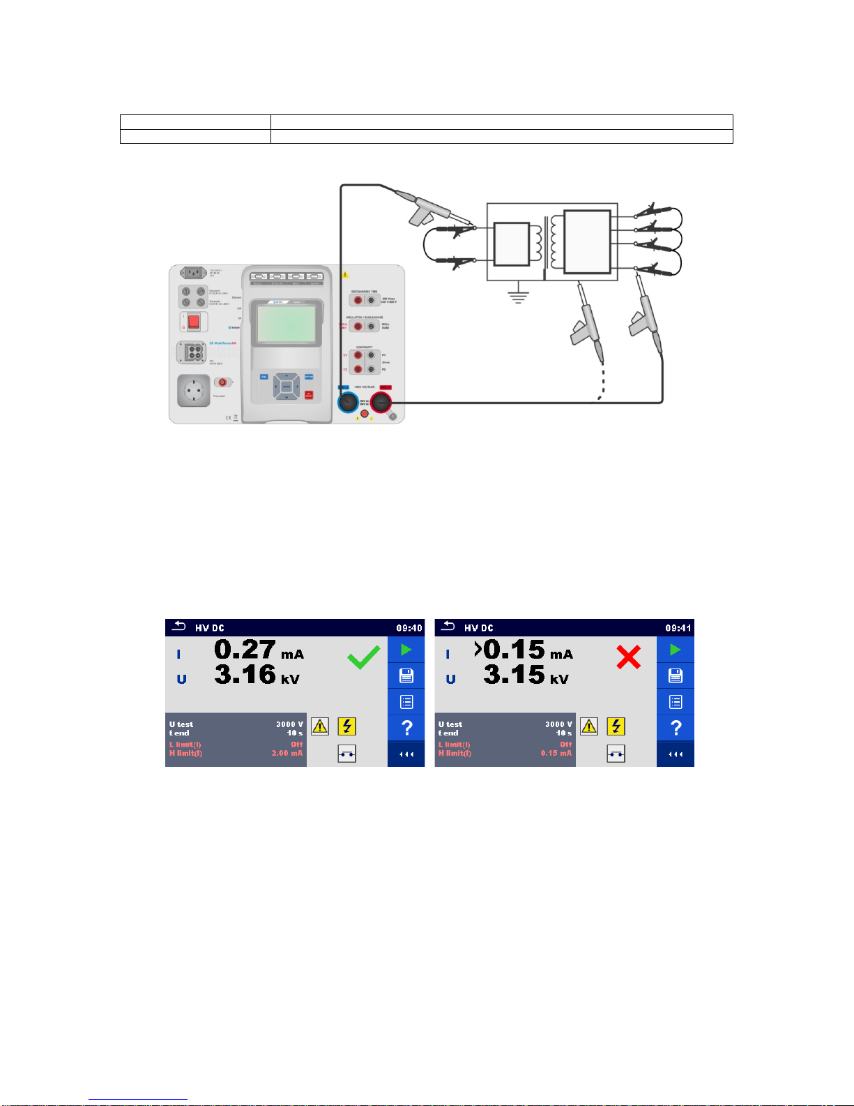
Figure 4.11: HV AC measurement

16
HV AC measurement procedure
Select the HV AC function.
Set test parameters / limits.
Connect HV test leads to HV(~,+) and HV(~,-) terminals on the instrument.
Connect HV test leads to device under test.
Start measurement.
Measurement can be stopped manually or by timer.
Save results (optional).
Figure 4.12: Examples of HV AC meaasurement results
Note:
First HV measurement after power on the instrument (if password protection is enabled) or first HV
measurement after enabling or changing password require entering password for enabling HV test.
4.1.4 HV DC
IMPORTANT SAFETY NOTE
Refer to chapter 1.1 Warnings and notes for more information regarding safe use of the instrument.
Figure 4.13: HV DC test menu
Test results / sub-results
U................... measured test voltage
I.................... test current
Test parameters
DC test voltage
U test [500 V ... 6000 V in steps of 50 V]
Duration
t end [Off, 1 s ... 120 s]
17
Test limits
High limit (I)
H limit [0.05 mA ... 10.0 mA ]
Low limit (I)
L limit [Off, 0.05 mA ... 10.0 mA]
Test circuit
Figure 4.14: HV DC measurement
HV DC measurement procedure
Select the HV DC function.
Set test parameters / limits.
Connect HV test leads to HV(~,+) and HV(~,-) terminals on the instrument.
Connect HV test leads to device under test.
Start measurement.
Measurement can be stopped manually or by timer.
Save results (optional).
Figure 4.15: Examples of HV DC measurement results
Note:
First HV measurement after power on the instrument (if password protection is enabled) or first HV
measurement after enabling or changing password require entering password for enabling HV test.
18
4.1.5 HV AC programmable
IMPORTANT SAFETY NOTE
Refer to chapter 1.1 Warnings and notes for more information regarding safe use of the instrument.
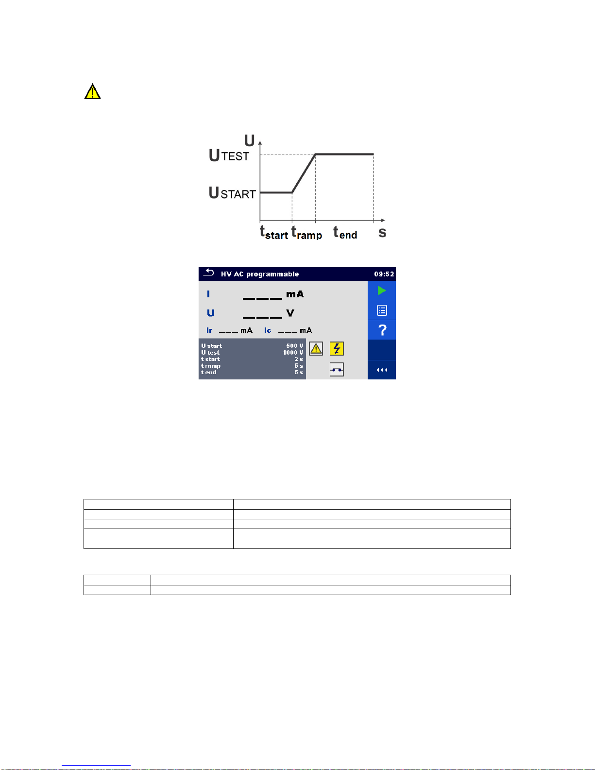
In the HV AC programmable test the time dependency of high voltage can be set according to diagram on Figure 4.16.
Figure 4.16: Voltage / time diagram of the HV AC programmable test
Figure 4.17: HV AC programmable test menu
Test results / sub-results
I.................... test current
U................... measured test voltage
Ir................... resistive portion of test current
Ic .................. capacitive portion of test current
Test parameters
Starting AC test voltage
U start [100 V ... 5000 V in steps of 10 V]
AC test voltage
U test [100 V ... 5000 V in steps of 10 V]
Duration of starting voltage
t start [1 s ... 120 s ]
Duration of ramp
t ramp [2 s ... 60 s ]
Duration of test voltage
t end [Off, 1 s ... 120 s ]
Test limits
High limit (I)
H limit [0.5 mA ... 100 mA ]
Low limit (I)
L limit [Off, 0.5 mA ... 100 mA]

19
Test circuit
Figure 4.18: HV AC programmable test
HV AC programmable test procedure
Select the HV AC programmable function.
Set test parameters / limits.
Connect HV test leads to HV(~,+) and HV(~,-) terminals on the instrument.
Connect HV test leads to device under test.
Start measurement.
Measurement can be stopped manually or by timer.
Save results (optional).
Figure 4.19: Examples of HV AC programmable test results
Note:
First HV measurement after power on the instrument (if password protection is enabled) or first HV
measurement after enabling or changing password require entering password for enabling HV test.
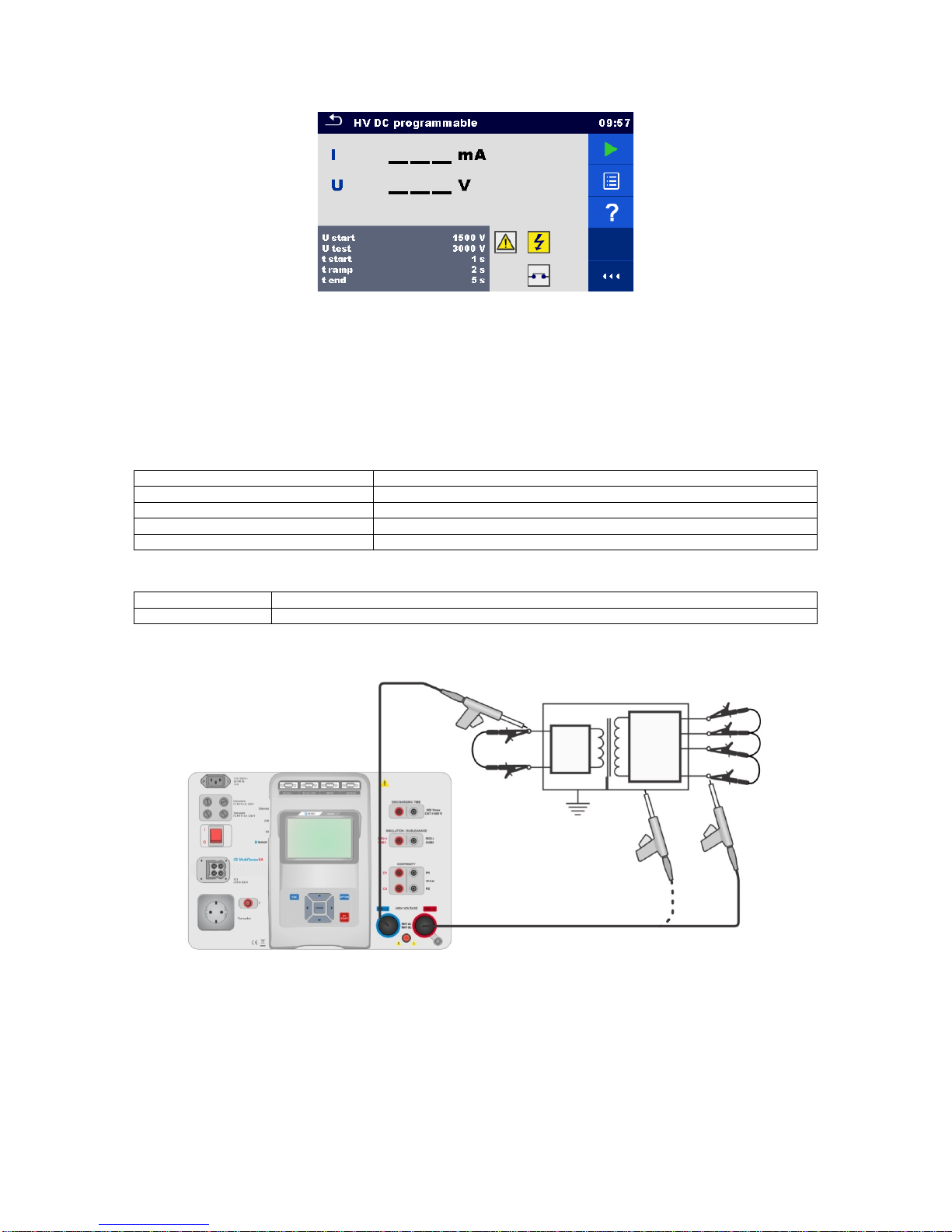
4.1.6 HV DC programmable
IMPORTANT SAFETY NOTE
Refer to chapter 1.1 Warnings and notes for more information regarding safe use of the instrument.
In the HV DC programmable test the time dependency of high voltage can be set according to diagram on Figure 4.16.
20
Figure 4.20: HV DC programmable test menu
Test results / sub-results
U................... measured test voltage
I.................... test current
Ic .................. capacitive portion of test current
Ir................... resistive portion of test current
Test parameters
Starting DC test voltage
U start [500 V ... 6000 V in steps of 50 V]
DC test voltage
U test [500 V ... 6000 V in steps of 50 V]
Duration of starting voltage
t start [1 s ... 120 s ]
Duration of ramp
t ramp [2 s ... 60 s ]
Duration of test voltage
t end [Off, 1 s ... 120 s ]
Test limits
High limit (I)
H limit [0.05 mA ... 10.0 mA ]
Low limit (I)
L limit [Off, 0.05 mA ... 10.0 mA]
Test circuit
Figure 4.21: HV DC programmable test
Table of contents
Other Chauvin Arnox Multimeter manuals


