Chauvin Arnox C.A 6418 User manual

2
Thank you for purchasing this C.A 6418 oblong ground tester clamp.
For best results from your instrument:
read these operating instructions carefully,
comply with the precautions for use.
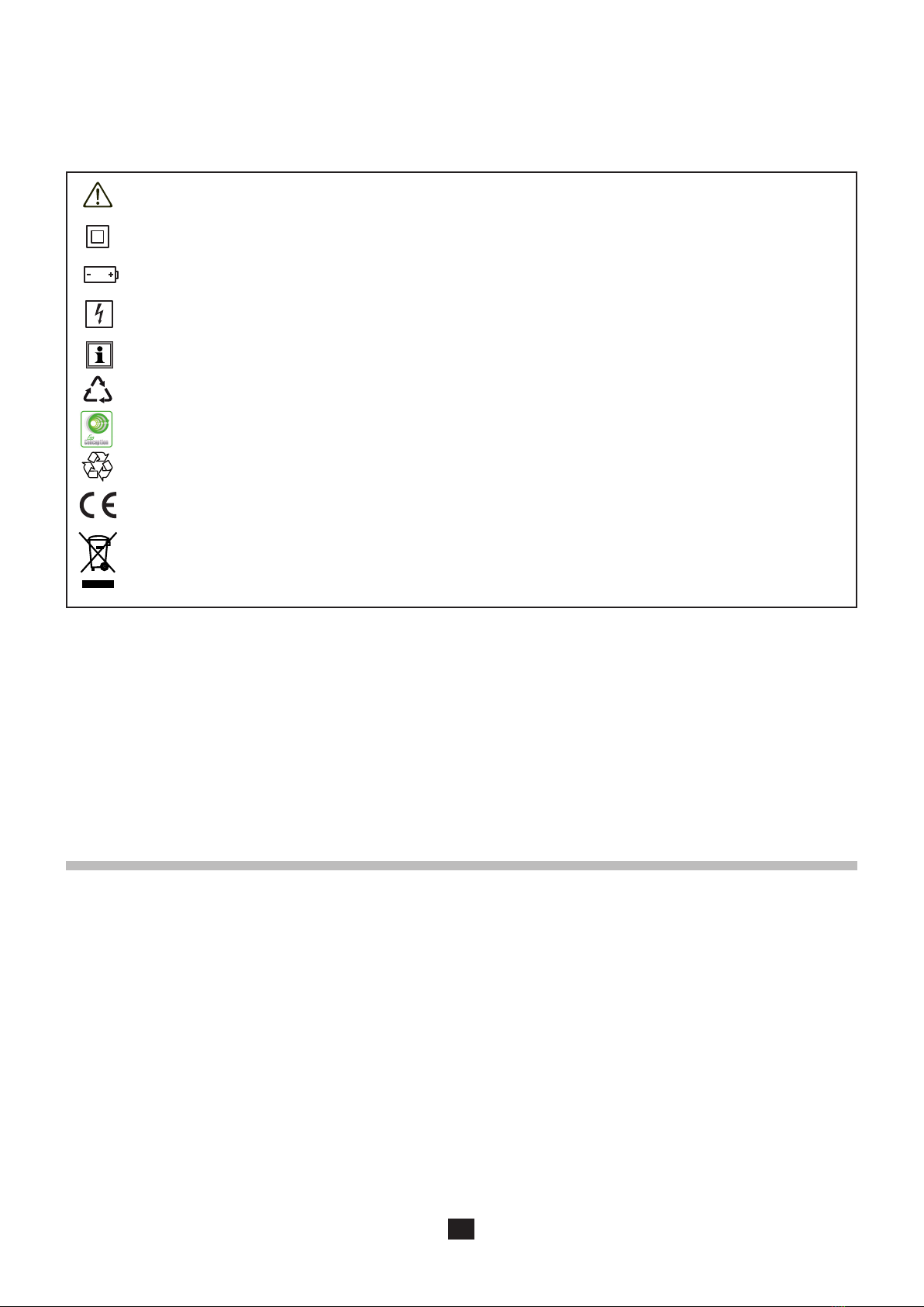
WARNING, risk of DANGER! The operator must refer to these instructions whenever this danger symbol appears.
Equipment protected throughout by double insulation.
Battery.
Application or withdrawal authorized on uninsulated or bare conductors at dangerous. Type A current sensor per IEC
61010 2 032.
Information or useful tip.
The product has been declared recyclable after analysis of its life cycle in accordance with the ISO 14040 standard.
Chauvin Arnoux has adopted an Eco-Design approach in order to design this appliance. Analysis of the complete
exceeds regulation requirements with respect to recycling and reuse.
The CE marking indicates conformity with European directives, in particular LVD and EMC.
The rubbish bin with a line through it indicates that, in the European Union, the product must undergo selective disposal
in compliance with Directive WEEE 2002/96/EC. This equipment must not be treated as household waste.
Denition of measurement categories
Measurement category IV corresponds to measurements taken at the source of low-voltage installations.
Example: power feeders, counters and protection devices.
Measurement category III corresponds to measurements on building installations.
Measurement category II corresponds to measurements taken on circuits directly connected to low-voltage installations.
Example: power supply to domestic electrical appliances and portable tools.
PRECAUTIONS FOR USE
This instrument is compliant with safety standard IEC 61010-2-032, for voltages up to 100V in category IV or 150V in category III.
installations.
The operator and/or the responsible authority must carefully read and clearly understand the various precautions to be taken in
use. The operator and/or the responsible authority must carefully read and clearly understand the various precautions to be taken
in use. Sound knowledge and a keen awareness of electrical hazards are essential when using this instrument.
The safety of any system in which this instrument might be incorporated is the responsibility of the integrator of the system.
Do not use the clamp above its rated frequency, since this might cause it to overheat dangerously.
Do not use the instrument on networks of which the voltage or category exceeds those mentioned.
Observe the environmental conditions of use.
Do not use the instrument if it seems to be damaged, incomplete, or poorly closed.

3
Before each use, check the condition of the insulation on the housing. Any item of which the insulation is deteriorated (even
partially) must be set aside for repair or scrapping.
Before using your instrument, check that it is perfectly dry. If it is wet, it must be thoroughly dried before it can be connected or used.
Avoid impacts on the measurement head, in particular the air gap.
Keep the surfaces of the air gap clean; even a little dirt can cause the clamp to malfunction.
Use personal protection equipment systematically.
All troubleshooting and metrological checks must be done by competent accredited personnel.
CONTENTS
1. PRESENTATION ..................................................................................................................................................................... 4
1.1. Unpacking....................................................................................................................................................................... 4
1.2. Description of the device ................................................................................................................................................ 4
1.3. Function keys ................................................................................................................................................................. 6
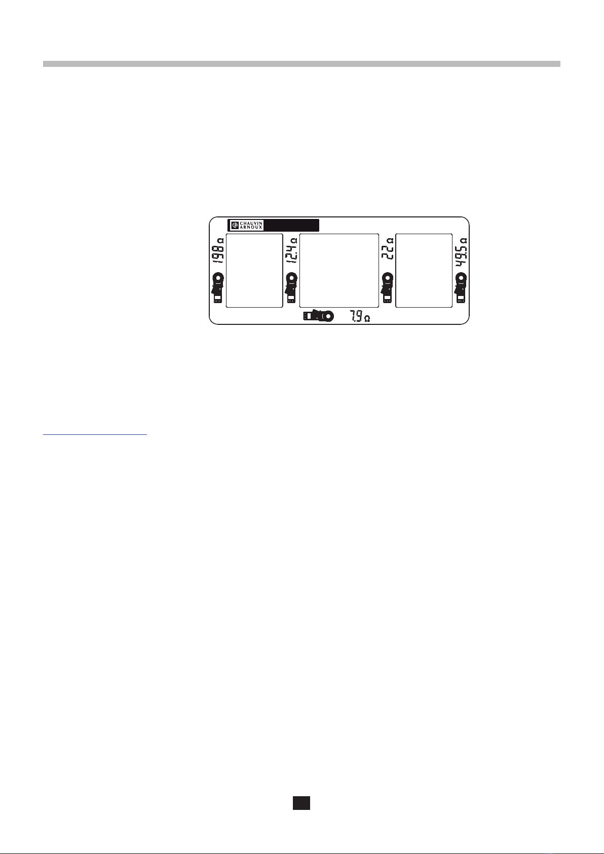
1.4. Display............................................................................................................................................................................ 6
1.5. Inserting the batteries ..................................................................................................................................................... 7
1.6. Setting the date and time................................................................................................................................................ 7
2. USE........................................................................................................................................................................................... 8
2.1. General........................................................................................................................................................................... 8
2.2. Impedance and current measurement............................................................................................................................ 8
2.3. Current measurement................................................................................................................................................... 10
..............................................................................................................................11
2.5. Adjustment.................................................................................................................................................................... 12
2.6. Errors............................................................................................................................................................................ 14
2.7. Automatic stop .............................................................................................................................................................. 14
2.8. Storage ......................................................................................................................................................................... 15
3. TECHNICAL CHARACTERISTICS ..................................................................................................................................... 17
3.1. General reference conditions ....................................................................................................................................... 17
3.2. Electrical characteristics ............................................................................................................................................... 17
3.3. Variation in the domain of use ...................................................................................................................................... 18
3.4. Power supply ................................................................................................................................................................ 19
3.5. Environmental conditions ............................................................................................................................................. 19
3.6. Mechanical characteristics .......................................................................................................................................... 20
3.7. Compliance with international standards...................................................................................................................... 20
3.8. Electromagnetic compatibility (EMC)............................................................................................................................ 20
4. MAINTENANCE..................................................................................................................................................................... 21
4.1. Cleaning ....................................................................................................................................................................... 21
4.2. Replacement of the batteries........................................................................................................................................ 21
5. WARRANTY .......................................................................................................................................................................... 23

4
1. PRESENTATION
1.1. UNPACKING
1.1.1. DELIVERY CONDITION
The instrument is delivered in a carrying case containing:
4 LR6 or AA batteries.
A wrist strap
One multilingual safety data sheet.
One multilingual quick start guide.
1.1.2. ACCESSORIES
CL1 calibration loop.
1.1.3. REPLACEMENT PARTS
Carrying case MLT110.
Set of 12 LR6 or AA batteries.
For the accessories and spares, consult our web site:
www.chauvin-arnoux.com
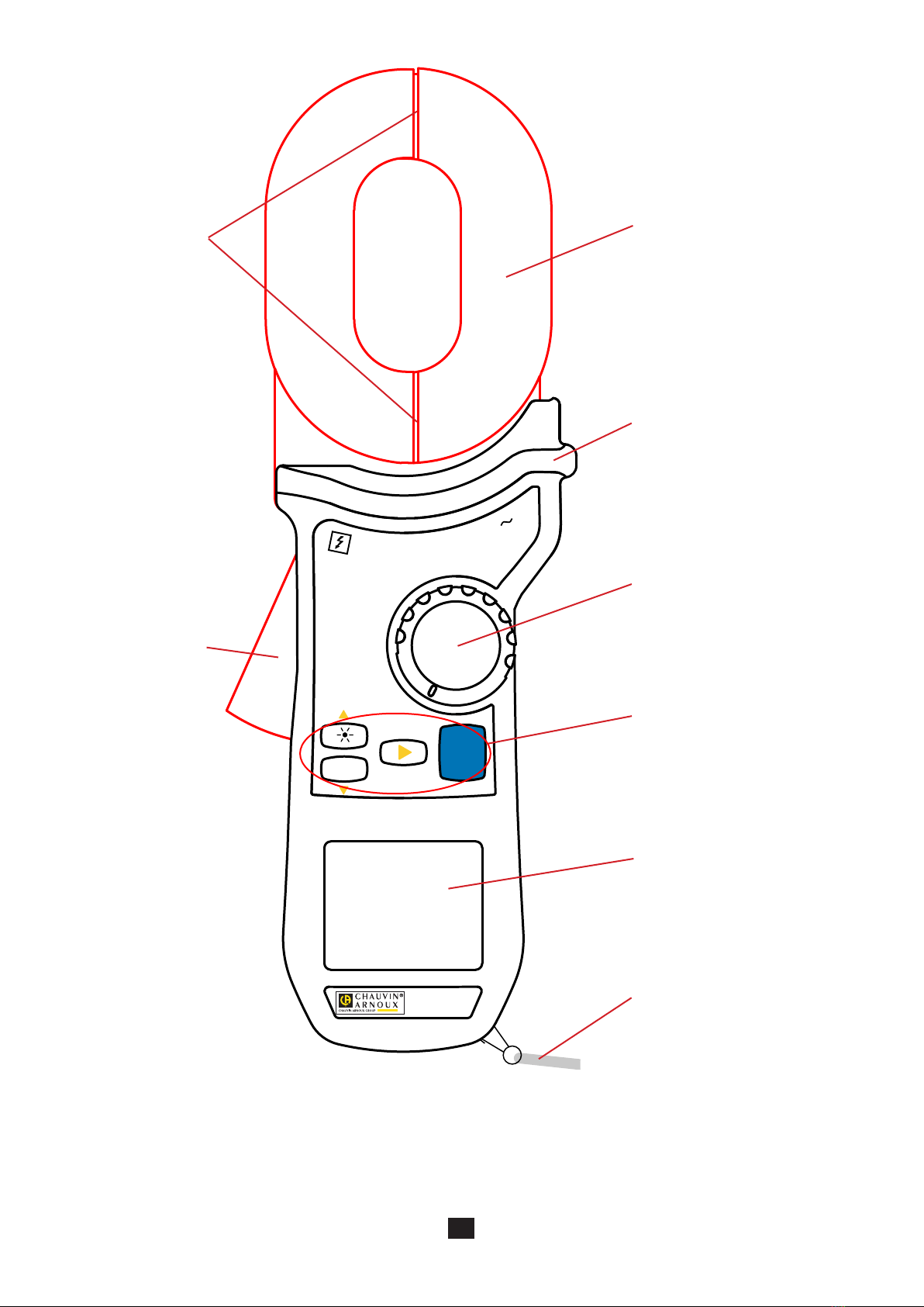
1.2. DESCRIPTION OF THE DEVICE
The C.A 6418 is used to make loop impedance measurements in a parallel earth network, for example for power distribution poles,
overhead contact lines, etc. These measurements are simpler to perform than the traditional measurements with two auxiliary rods.
The C.A 6418 can make loop impedances measurements with good accuracy at low values, and AC current measurements.
The C.A 6418 is simple to use. Its large measurement head can clamp bars up to 30x40mm.
Its memory function is used to record and read back the measurements.
Its OLED (Organic Light Emitting Diode) display unit is very easy to read, even in direct sunlight.
Calibration Loop

5
1
0
0
V
C
A
T
I
V
2
0
A
SET-UP
MR
A
OFF
Ω+ A
C.A 6418
GROUND TESTER
MEM
HOLD
Measurement head.
Guard.
Trigger.
4 function keys.
Rotary switch to turn the instrument
on and select measurement, SET-
UP, or read memory.
OLED display unit.
Wrist strap.
Air gaps.

6
1.3. FUNCTION KEYS
As a general rule, the functions shown in white on the keys are available when the switch is set to Ω+A or A.
MR or SET-UP.
Key Function
The
MEM The MEM key is used to record the measurement displayed.
HOLD The HOLD key is used to freeze, then unfreeze, the display of the measurement.
to browse in the SET-UP menu and change the value of the parameter selected,
to browse in memory read (MR).
When the switch is set to Ω+A or A
When the switch is set to SET-UP
When the switch is set to MR
and time.
1.4. DISPLAY
Secondary display unit for current.
Main display unit for loop impedance.
Alarm display unit.
Memory display unit.
When the measurement exceeds the limits of the measurement range, the instrument displays OR.

7
1.5. INSERTING THE BATTERIES
Refer to §4.2.
1.6. SETTING THE DATE AND TIME
During the first use, set the date and time of your instrument. When you switch it on by turning the switch to Ω+A, the instrument
prompts you to set the date.
keys.
The instrument then displays the time to be set. First choose 24h

8
Set the switch to Ω+A.
2. USE
2.1. GENERAL
When switched on, the instrument makes an adjustment. The jaws of the clamp must therefore be closed and there must not be
any conductor in the measurement head.
Press the trigger to open the jaws of the clamp
and clamp a conductor that is part of the loop to be
measured.
When the clamp is open, the symbol is displayed
and the instrument cannot make any measurement.
SET-UP
MR
A
Ω+ A
OFF
SET-UP
MR
A
Ω+ A
OFF
1
0
0
V
C
A
T
I
V
2
0
A
SET-UP
MR
A
OFF
Ω+ A
C.A 6418
GROUND TESTER
MEM
HOLD
1
0
0
V
C
A
T
I
V
2
0
A
SET-UP
MR
A
OFF
Ω+ A
C.A 6418
GROUND TESTER
MEM
HOLD
If the instrument fails to make the adjustment, it reports an error by displaying Err. CAL
check that the air gaps are clean, then switch the instrument back on.
2.2. IMPEDANCE AND CURRENT MEASUREMENT
1
0
0
V
C
A
T
I
V
2
0
A
SET-UP
MR
A
OFF
Ω+ A
C.A 6418
GROUND TESTER
MEM
HOLD

9
The earth electrode to be measured, Rx, is in parallel with the others via earth ZEand guard wire ZS.
The impedance measured by the clamp is slightly greater than Rx. In the case of a regular check, a sudden change in the value
measured shows that there is a problem.
used for subsequent checks.
During the impedance measurement, the instrument emits a discontinuous audible signal (beep, beep). This sound cannot
as a function of the frequency and amplitude of the current measured.
2.2.2. AFTER THE MEASUREMENT
Once the measurement has stabilized, you can press the HOLD key to freeze it and/or MEM to record it.
R2RnR1Rx
ZS
I
ZE
HOLD
MEM
2.2.1. CONNECTION

10
2.2.3. PRE-HOLD FUNCTION
You can also use the pre-HOLD function (see §2.4), which freezes the measurement automatically when the jaws of the clamp are
opened. This can be useful when you have only one hand free to make a measurement.
2.2.4. ALARMS
To facilitate making the measurements, you can program an alarm on the impedance measurement value (see §2.4) and/or the
current measurement value (see §2.4). You then know whether the measurement is OK without looking at the display unit.
The alarm part of the display unit blinks and the instrument emits
a continuous audible signal.
If you set alarms on both the impedance and the current and both
alarm thresholds are exceeded, it is the alarm on the current that
has priority.
Once the measurement has stabilized, you can press the HOLD key to freeze it and/or MEM to record it.
You can also use the pre-HOLD function (see §2.4), which freezes the measurement automatically when the jaws of the clamp are
opened. This can be useful when you do not have both hands free to make a measurement.
To facilitate making the measurements, you can program an alarm on the current measurement value (see §2.4). You then know
whether the measurement is OK without looking at the display unit.
2.3. CURRENT MEASUREMENT
The current measurement alone is identical to the current measurement with the impedance measurement.
SET-UP
MR
A
Ω+ A
OFF
Set the switch to A.Press the trigger to open the jaws of the clamp and clamp the conductor in which the current
I

11
SET-UP
MR
A
Ω+ A
OFF
Set the switch to SET-UP.
CLR (erase memory) menu.
5 audible beeps before erasing the memory.
SND menu (activation of the sound).
symbol.
When it is displayed, the instrument emits an audible signal when keys are pressed and when alarm
thresholds are crossed.
During the measurements (when the switch is set to Ω+A or A
or deactivates the audible signal.
STOP menu (automatic standby).
symbol
(permanent operation).
When it is displayed, automatic switching of the instrument to standby at the end of 5 minutes is disabled.
ALΩ menu (loop impedance alarm).
: there is no impedance measurement alarm.
AL A menu (current alarm).
: there is no current measurement alarm.
: there is an alarm when the current is >30mA.
20.0 A. A long press scrolls the values faster.
2.4. CONFIGURING THE INSTRUMENT (SET-UP)

12
DATE menu (setting of the date).
For a more detailed procedure, see §1.6.
HOUR menu (setting of the time).
For a more detailed procedure, see §1.6.
HOLD menu (activation of the pre-HOLD function).
symbol.
When it is displayed, the pre-HOLD function is activated. This means that, if the measurement is
stable, it is frozen when the clamp is opened.
VER menu (display of the software version).
CAL menu (adjustment of the instrument).
This menu is used for the adjustment of the instrument. In order to prevent handling errors, access to
2.5. ADJUSTMENT
2.5.1. ADJUSTMENT OF THE IMPEDANCE MEASUREMENT
The instrument then alternately displays NO LOOP and PRESS RT to indicate that the clamp must
The instrument adjusts the empty clamp. Then it makes the adjustment on an internal resistance of
PASS or FAIL depending on whether the adjustment
succeeded or failed.

13
2.5.2. ADJUSTMENT OF THE CURRENT MEASUREMENT
You must have a stabilized current source to generate AC currents between 0.1 and 10A.
Step 1/7. The instrument alternately displays 100mA SET and PRESS RT. Clamp a cable in which
I
I
I
I = 100 mA
I = 5 A
I = 15 A
Step 2/7
Step 3/7. The instrument alternately displays 5.00A SET and PRESS RT. Clamp a cable in which
In the event of failure, repeat the procedure.
or
Step 4/7. The instrument performs the second part of the current measurement adjustment.
Step 5/7. The instrument alternately displays 15.00A SET and PRESS RT. Clamp a cable in which
Step 6/7. The instrument performs the third part of the current measurement adjustment.
Step 7/7. When it has terminated, it displays the result: PASS or FAIL depending on whether the

14
2.6. ERRORS
During the measurement, the instrument reports any errors.
Display of the NOISE symbol during the impedance measurement reports a current that is too high
(>5A) or a voltage that is too high (ZxI> 25V). The accuracy of the measurement displayed is uncertain.
When the current exceeds 10A, the impedance measurement is not displayed.
OR.
When the current measurement is >20A, the instrument so indicates.
LOOP, because the value is very low for an earth loop impedance.
Check your connection; in other words, check that you have not clamped a local loop rather than an
earth loop.
2.7. AUTOMATIC STOP
After 5 minutes of operation with no sign of the user’s presence (key press or rotation of the switch), the instrument switches to
standby.
Simply press any key or turn the switch to exit from standby. The instrument restarts without repeating the calibration procedure if
it has not been on standby for more than 15 minutes.
It is possible to disable automatic standby; refer to §2.4 (STOP menu). The symbol is then displayed.
2.5.3. RESTORING THE FACTORY VALUES
configuration and stored measurements are not erased.
The instrument displays PRESS RT
When it has terminated, the instrument displays the result: PASS or FAIL

15
2.8. STORAGE
2.8.1. RECORDING A MEASUREMENT
MEM
To record a measurement, press the MEM key.
HOLD key to freeze the measurement.
For it to be possible to record a measurement, the batteries must not be discharged. This means that the symbol must
not be displayed.
2.8.2. REREADING THE RECORDS
The measurement is recorded in the memory slot of which the number is displayed (here
slot number 2).
It is recorded with all accompanying information:
the date and time,
any alarms and their status (triggered or not),
any errors (NOISE, OR, LOOP),
ancillary displays (HOLD, ).
SET-UP
MR
A
Ω+ A
OFF
Set the switch to MR.
The instrument displays the last measurement recorded.
2.8.3. ERASING ALL RECORDS
SET-UP
MR
A
Ω+ A
OFF
Set the switch to SET-UP.
Then follow the procedure described in §2.4 in the
CLR menu.
When you return to the MR setting, the instrument
indicates that the memory is empty.

16
2.8.4. MEMORY FULL
You can record up to 300 measurements (numbered from 0 to 299).
If you continue recording, measurement number 300 overwrites measurement number 0, measurement 301 overwrites measurement
1, and so on.
The instrument reports this by alternately displaying FULL and the memory slot number.
You can continue like this up to number 9999, at which point recording becomes impossible and you must erase the memory to
be able to resume recording.

17
3. TECHNICAL CHARACTERISTICS
3.1. GENERAL REFERENCE CONDITIONS
Quantities of inuence Reference values
Temperature 23 ±3°C
Relative humidity 50 ±10%RH
Supply voltage 6 ±0.2V
<1V/m
<40A/m
Operating position clamp horizontal
Position of the conductor in the jaws centred
Adjacent conductors carrying current in impedance measurement At least 10cm
Magnetic mass At least 10cm
Frequency 50Hz, sinusoidal
Level of distortion <0.5%
Current present in impedance measurement 0mA
The intrinsic uncertainty
The operational uncertainty
The uncertainties are expressed as a percentage of the reading (L) and as a number of display counts (R):
±(a%L+b.R)
3.2. ELECTRICAL CHARACTERISTICS
3.2.1. IMPEDANCE MEASUREMENTS
Particular conditions of reference
Inductance in series with the resistance: zero.
Specied measurement
range 0,010 to 0,099 Ω 0,10 to 0,99 Ω 1,0 to 49,9 Ω 50 to 149 Ω
Resolution (R)
Intrinsic uncertainty (δ) ± (1,5%L + 2 R) ± (1,5%L + 2 R) ± (2,5%L + 2 R)
No-load voltage
Specied measurement
range 150 to 245 Ω 250 to 440 Ω 450 to 640 Ω 650 to 1 200 Ω
Resolution (R)
Intrinsic uncertainty (δ) ± (5%L + 2 R) ± (10%L + 2 R) ± (15%L + 2 R) ± (20%L + 2 R)
No-load voltage

18
3.2.2. CURRENT MEASUREMENTS
Particular conditions of reference
Frequency of the signal: 47 to 800Hz
Specied measurement
range 0,50 to 9,995 mA 10,00 to 99,90 mA 100,0 to 299,0 mA 0,300 to 2,990 A
Resolution (R) 50 µA 100 µA 1 mA 10 mA
Intrinsic uncertainty (δ) ± (2%L + 200 µA) ± (2%L + R) ± (2%L + R) ± (2%L + R)
Specied measurement
range 3,00 to 20,00 A
Resolution (R) 100 mA
Intrinsic uncertainty (δ) ± (2%L + R)
Beyond 20A and 800Hz, the clamp may overheat dangerously.
3.2.3. STORAGE
Number of records: 300.
3.3. VARIATION IN THE DOMAIN OF USE
Z = impedance
I = current
δ= intrinsic uncertainty given in §3.2.
R = resolution given in §3.2.
For the impedance measurement
Quantities of inuence Range of inuence Inuence
Typical Maximum
Temperature -20 to + 55 °C 0.5 δ/ 10°C ± R 1.5 δ/ 10°C + R
Relative humidity 10 to 90 %RH 1 δ± R 2 δ± R
Supply voltage 4 to 6.5 V 0.05 δ± R 0.1 δ± R
Position of conductor from the edge to the centre
0.2 δ± R
Z ≥
0.5 δ± R
0.4 δ± R
Z ≥
1 δ± R
Position of clamp +/- 180°
0.25 δ± R
Z ≥
0.5 δ± R
0.5 δ± R
Z ≥
1 δ± R
Proximity to magnetic mass Sheet steel 1mm thick against
the air gap 0.1 δ± R 0.5 δ± R
50/60Hz 30 A/m 0.05 δ± R 0.1 δ± R
Adjacent conductor I < 40A
0.25 δ± R
Z ≥
0.4 δ± R
0.5 δ± R
Z ≥
0.8 δ± R
Leakage current in the loop
from 50 to 60Hz
I <10 A. ZxI <75 V
Z x I < 20 V 0.5 δ± R 1 δ± R
20 V ≤Z x I < 40 V 1 δ± R 3 δ± R
40 V ≤Z x I 2 δ± R 4 δ± R
Z ≥ 0.5 δ± R 1 δ± R
Loop inductance 0 to 500 µH The instrument displays Z at the measurement frequency
(2083Hz)

19
For the current measurement
Quantities of inuence Range of inuence Inuence
Typical Maximum
Temperature -20 to + 55 °C 0.5 δ/ 10°C ± R 1.5 δ/ 10°C + R
Relative humidity 10 to 90 %RH 0.5 δ± R 1 δ± R
Supply voltage 4 to 6.5 V 0.05 δ± R 0.1 δ± R
Position of conductor from the edge to the centre 0.05 δ± R 0.2 δ± R
Position of clamp +/- 180° 0.1 δ± R 0.25 δ± R
Proximity to magnetic mass Steel sheet 1mm thick against
air gap 0.1 δ± R 0.2 δ± R
50/60Hz
10 A/m 0.75 mA 1.5 mA
30 A/m 2 mA 4.5 mA
100 A/m 8 mA 15 mA
Deformation of the leakage current
IEC 61557-13
5 % to 150 Hz at 0°
6 % to 250 Hz at 180°
5 % to 350 Hz at 0°
0.05 δ± R 0.1 δ± R
Adjacent conductor I < 40A > 70 dB > 66 dB
Frequency of the leakage current 47 to 800 Hz 10.5 δ± R 1 δ± R
1: For the whole current measurement range
3.4. POWER SUPPLY
The instrument is powered by four 1.5V AA batteries (LR6 alkaline batteries; NiMH rechargeable batteries may also be used).
The voltage range ensuring proper operation is from 4V to 6.5V.
The battery life of the instrument is 20 hours, or approximately 2400 30-second measurements.
3.5. ENVIRONMENTAL CONDITIONS
The conditions of ambient temperature and relative humidity are given by the following graph:
%RH
75
60
20
-20-40 0 20 26 35 40 55 70
°C
95
90
40
321
1 = Domain of reference.
2 = Domain of use.
3 = Domain of storage without batteries.
Indoor use.
Altitude <2000m
Pollution degree 2

20
3.6. MECHANICAL CHARACTERISTICS
Dimensions (L x W x H) 300 x 106 x 56mm
Weight approximately 1.2kg
Clamping diameter 32mm or a 30 x 40mm or 20 x 55mm bar
55
20
Ø32
40
30
Ingress protection IP40 per IEC 60529
3.7. COMPLIANCE WITH INTERNATIONAL STANDARDS
The device is compliant with standard IEC 61010-1 and IEC 61010-2-032, 100V category IV or 150V category III.
3.8. ELECTROMAGNETIC COMPATIBILITY (EMC)
The device is compliant with standard IEC 61326-1.
Table of contents
Popular Test Equipment manuals by other brands

Power Fist
Power Fist 8494031 user manual

Isotech
Isotech IIT 1500 instruction manual

Unit
Unit MSO Series quick start guide

Kyoritsu Electrical Instruments Works, Ltd.
Kyoritsu Electrical Instruments Works, Ltd. KEW8031F instruction manual

AU Tool
AU Tool BST-100 user manual

Pressure-Pro
Pressure-Pro TPMS+ user manual