CHD 8-252 User manual
7
Model 8-252
ver. 1.2
Microprocessor
Controlled
Model 8-252
FULL A PWR PANIC
FUNCTION
B
MIDIBUFF
MIDI
Merge Box
MMB
2x2
I/OIn/Out-A
PARAMETER
In/Out-B
MIDI Data Filter Aut-Pan
1 2 3 4 5 6 7 8 9 10
OWNER’S MANUAL
© 2009 CHD Elektroserv is

MMB 2x2
MIDI Merge Box
Model 8-252 ver. 1.2
Copyri ght © 2009 CHD Elektroservis
All rights reserved. No part of this publication may be reproduced in any form without the written permis sion of CHD Elektroservis, s.r.o.
2
Content
page
1. Introduction . . . . . . . . . . . . . . . . . . . . . . . . . . . . . . . . . . . . . . . 3
1.1. Controllers and indicators, connectors . . . . . . . . . . . . . . . . . . . . . . . . . 3
1.2. Device function . . . . . . . . . . . . . . . . . . . . . . . . . . . . . . . . . . . . . 3
1.3. Usage of device . . . . . . . . . . . . . . . . . . . . . . . . . . . . . . . . . . . . . 4
2. Device installation . . . . . . . . . . . . . . . . . . . . . . . . . . . . . . . . . . . . 4
2.1. Connection to MIDI system . . . . . . . . . . . . . . . . . . . . . . . . . . . . . . . 4
2.2. Connection to power supply adapter . . . . . . . . . . . . . . . . . . . . . . . . . . 5
3. Attendance of device . . . . . . . . . . . . . . . . . . . . . . . . . . . . . . . . . . . 5
3.1. Initialization sequence . . . . . . . . . . . . . . . . . . . . . . . . . . . . . . . . . . 5
3.2. System parameters . . . . . . . . . . . . . . . . . . . . . . . . . . . . . . . . . . . . 5
3.3. Operating status indication . . . . . . . . . . . . . . . . . . . . . . . . . . . . . . . . 6
3.3.1. Power on indicator . . . . . . . . . . . . . . . . . . . . . . . . . . . . . . . . . . . . 6
3.3.2. Indication of MIDI outputs activity . . . . . . . . . . . . . . . . . . . . . . . . . . . . 6
3.3.3. Indication of data caching buffers overflowing . . . . . . . . . . . . . . . . . . . . . . 6
4. Data filters . . . . . . . . . . . . . . . . . . . . . . . . . . . . . . . . . . . . . . . . 7
4.1. Setting of filters . . . . . . . . . . . . . . . . . . . . . . . . . . . . . . . . . . . . . . 7
5. "PANIC" function . . . . . . . . . . . . . . . . . . . . . . . . . . . . . . . . . . . . . 8
5.1. Manual activation . . . . . . . . . . . . . . . . . . . . . . . . . . . . . . . . . . . . 8
5.2. Automatic activation . . . . . . . . . . . . . . . . . . . . . . . . . . . . . . . . . . . 8
6. Technical specifications . . . . . . . . . . . . . . . . . . . . . . . . . . . . . . . . . 9
7. Warranty conditions . . . . . . . . . . . . . . . . . . . . . . . . . . . . . . . . . . . 9
Appendix: FAQ . . . . . . . . . . . . . . . . . . . . . . . . . . . . . . . . . . . . . . . . . . 10
Manufacturer :
CHD Elektroservis
Nad kundratkou 27, 19000 Praha 9
Czech Republic
info@chd-el.cz
www.chd-el.cz

MMB 2x2
MIDI Merge Box
Model 8-252 ver. 1.2
Copyri ght © 2009 CHD Elektroservis
All rights reserved. No part of this publication may be reproduced in any form without the written permis sion of CHD Elektroservis, s.r.o.
3
1. INTRODUCTION
MMB 2x2 is device that merges MIDI data from four MIDI transceivers. Algorithm of internal
operating system and size of data buffers are chosen so that while merging data, all regulations “MIDI
Specification" given by MMA (MIDI Manufacturers Association) are adhered and that device can
process commands and messages of all MIDI standards.
During data merging, priority of different data types is taken into consideration, duplicate data
and all disallowed data (e.g. undefined state bytes, data bytes without state byte, etc.) is eliminated.
Operating system of MMB 2x2 fully respects communication regime „Running Status" – duplicate state
bytes are omitted from MIDI messages and conversely, state bytes are inserted to MIDI messages on
required positions. All above stated operations are carried out by MMB 2x2 automatically, interference
of attendance is not needed.
For increasing the utility value, device is complemented by user adjustable filters of MIDI data
and "Panic" function is also implemented.
1.1. CONTROLLERS AND INDICATORS, CONNECTORS
Pic. 1 – Panels of device
All sockets are on rear panel of the
device. LED indicators (diodes) and manual
controllers are on front panel of the device.
Placement and titles of all components are
shown on pic. 1.
1. System parameters selector
2. Indicator of overflowing of buffers
3. Data on bus A indikcator
4. Data on bus B indikcator
5. Power indicator
6. PANIC button
7. Socket for supply adapter
8. MIDI data input A
9. MIDI data output A
10. MIDI data input B
11. MIDI data output B
1.2. DEVICE FUNCTION
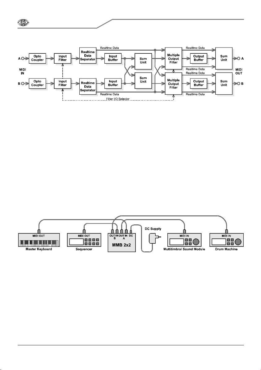
The device processes MIDI data in two identical and independent ways A and B. Signals from
MIDI buses coming to inputs MIDI-IN-A [8] and MIDI-IN-B [10] are galvanicaly insulated by
optocouplers and brought to input filters of MIDI data. Real time data with highest priority are
separated and then they are coming to outputs of signal ways directly if their filtration isn’t requested.
This guarantees minimal delay of MIDI synchronization data. Other data are stored in input caching
buffers and from here data are continuously drawn and merged with data from the other way. Resulting
data are filtered (if output filters are enabled) and stored in output data caching buffers. From there,
data are gradually sent to outputs MIDI-OUT-A [9] and MIDI-OUT-B [11].
Function block diagram of MMB 2x2 is shown on pic.2.
MMB 2x2
MIDI Merge Box
Model 8-252 ver. 1.2
Copyri ght © 2009 CHD Elektroservis
All rights reserved. No part of this publication may be reproduced in any form without the written permis sion of CHD Elektroservis, s.r.o.
4
Pic. 2 – Functional block diagram
1.3. USAGE OF DEVICE
Typical usage of Merge Box is shown on pic. 3. In this case, the device mixes data from master
keyboard and sequencer and resulting signal is brought to multitimbral (multi-voice) sound expander
and rhythmer. Each of MIDI data sources can independently control one or more voices of expander or
rhythmer. Any different transceiver of MIDI data (guitar converter, PC, rhythmer, etc.) can be obviously
connected instead of master keyboards and sequencer.
The device can be used only as MIDI Thru Box too. Source of MIDI data is connected to one of
MIDI inputs in that case and data for two MIDI receivers are on both MIDI outputs.
In case only one transceiver and only one receiver of MIDI data are connected, MMB 2x2 will
work as MIDI data filter. Type of filtered data can be chosen by user.
MMB 2x2 is designed so that all functions described above can be used simultaneously. It gives
many combinations of the device function.
Pic. 3 – Typical usage
2. DEVICE INSTALLATION
2.1. CONNECTION TO MIDI SYSTEM
MMB 2x2 is connected to MIDI buses by standard MIDI cables terminated by DIN 41524
connector (5 pins 180°). Data from transceivers is brought to inputs MIDI-IN-A [8] and MIDI-IN-B [10],
output data for MIDI receivers are brought to connectors MIDI-OUT-A [9] and MIDI-OUT-B [11]. Inputs
A / B and outputs A / B respectively are identical and they can be interchanged.
MMB 2x2
MIDI Merge Box
Model 8-252 ver. 1.2
Copyri ght © 2009 CHD Elektroservis
All rights reserved. No part of this publication may be reproduced in any form without the written permis sion of CHD Elektroservis, s.r.o.
5
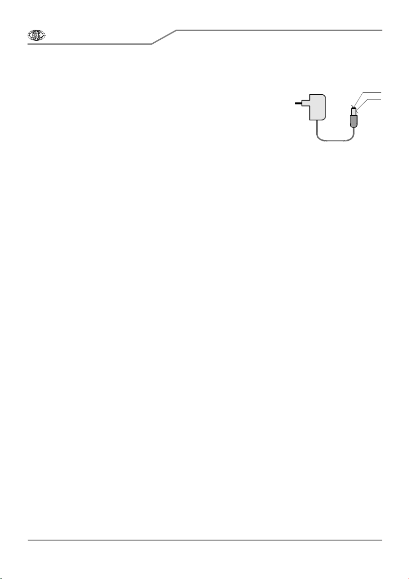
2.2. CONNECTION TO POWER SUPPLY ADAPTER
Pic. 4 – Supply adapter
Device is powered from external DC power supply (e.g. power
network adapter) connected to the DC [7] connector. Connector is of
standard design (diameter of central pin is 2.1 mm). External DC adapter
must be able to continuously supply current at least 100 mA, allowed
range of power supply voltage is 8 to 15 volts.
The connector of adapter must have + polarity on middle pin and –
polarity on jacket (see pic. 4). The polarity of power supply connector is
graphically illustrated on rear panel of the device. MMB 2x2 has built-in protection against supply
voltage polarity reversal. The device does not work in such case, but it will not be damaged.
3. ATTENDANCE OF DEVICE
3.1. INITIALIZATION SEQUENCE
Initialization sequence (hardware reset) of the device takes place automatically - always after
connection of power supply voltage. During initialization sequence, all functions of MMB 2x2 are set to
initial still states and all internal caching data buffers are cleared. At the same time, new current state
of PARAMETER [1] switch is read and according to its value, data filters and next system parameters
are set.
Cleanup of caching data buffers and reading of current state of PARAMETER [1] switch also
always takes place when the “Panic” function is activated, regardless whether the activation was
automatic or manual (pressing the PANIC [6] button). Manual initialization (as part of “Panic” function)
can be used when changes in settings of PARAMETER [1] switch are required to take place during
production – without the need of disconnecting from power supply adapter and then reconnecting the
device – or in case of caching data buffers overflow.
3.2. SYSTEM PARAMETERS
The way of operation of MMB 2x2 during MIDI data processing is determined by parameters
settings. Setting of parameters is done by PARAMETER [1] switch.
Setting of PARAMETER [1] switch is read always after resetting the device – when power supply
voltage is connected to connector DC [7] or when „Panic" function is activated. Changes in setting of
PARAMETER [1] switch made during operation of the device have no effect on operation of MMB 2x2.
It is necessary to confirm changes by pressing PANIC [6] button or by disconnecting and reconnecting
external power supply adapter to connector DC [7].
Sections 1 to 9 of PARAMETER [1] switch control activity of MIDI data filters – see chapter 4.
Data filtration.
Section 10 of PARAMETER [1] switch enables "Auto-Panic" function which initializes the device
automatically if a data caching buffer overflows. "Auto-Panic" function is enabled if section 10 of
PARAMETER [1] switch is in lower position (ON). If section 10 of PARAMETER [1] switch is in upper
position (OFF), "Auto-Panic" function is disabled and initialization of MMB 2x2 must be done manually
when a data caching buffer overflows.
Function of particular sections of PARAMETER [1] switch describes table 1.
- (GND)
+8~15
V
ca 2
V
A

MMB 2x2
MIDI Merge Box
Model 8-252 ver. 1.2
Copyri ght © 2009 CHD Elektroservis
All rights reserved. No part of this publication may be reproduced in any form without the written permis sion of CHD Elektroservis, s.r.o.
6
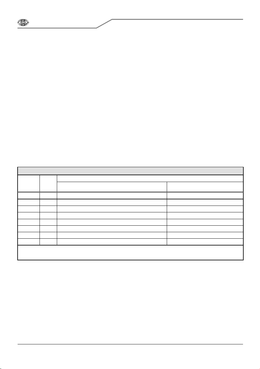
Table 1 – System parameters
DIL Switch
Section Parameter name Meanig and function
1 Filter In/Out-A Data way A: Filter of aftertouch commands (Off / On)
2 Filter In/Out-A Data way A: Filter of program changes (Off / On)
3 Filter In/Out-A Data way A: Filter of common system real time data (Off / On)
4 Filter In/Out-A Data way A: Filter of System Exclusive messages (Off / On)
5 Filter In/Out-B Data way B: Filter of aftertouch commands (Off / On)
6 Filter In/Out-B Data way B: Filter of program changes (Off / On)
7 Filter In/Out-B Data way B: Filter of common system real time data (Off / On)
8 Filter In/Out-B Data way B: Filter of System Exclusive messages (Off / On)
9 Filter In / Out Filters inserted into MIDI inputs (On) or into MIDI outputs (Off)
10 Auto-Panic Automatic launching of “Panic” function if a buffer overflows (Enabled / Disabled)
3.3. OPERATING STATUS INDICATION
Four LED indicators are on front panel of MMB 2x2. Attendants are continuously informed about
current state of the device during operation by these LEDs.
3.3.1. POWER ON INDICATOR
Red LED PWR [5] lights constantly while power supply adapter is connected to the device. It
indicates power-on state and serviceability of the device. If this LED is not on after connecting power
supply adapter, the adapter is probably malfunctioning or some fatal error occurred in MMB 2x2.
3.3.2. INDICATION OF MIDI OUTPUTS ACTIVITY
Green LEDs MIDI-A [3] and MIDI-B [4] respectively indicate activity of outputs MIDI-OUT-A [9]
and MIDI-OUT-B [11] respectively (i.e. fact that there are currently data being transferred through
outputs). Green LEDs MIDI-A [3] and MIDI-B [4] blink shortly always during transition of MIDI byte.
Individual blinks can blend in case of dense flow of data (more often than approx. every 100 ms), so
LEDs can be continuously on.
3.3.3. INDICATION OF DATA CACHING BUFFERS OVERFLOWING
Yellow LED BUFF-FULL [2] indicates overflowing of any of internal data caching buffers. If that
situation occurs, MMB 2x2 is unable to process MIDI data correctly and all activities of the device are
stopped. It is necessary to be aware of the fact that in case of overflowing of any buffer, all data stored
in all caching buffers are inevitably lost. It is necessary to carry out initialization of the device in order to
return it to normal operating state, i.e. disconnect and then reconnect external adapter to connector DC
[7] or simply press PANIC [6] button.
MMB 2x2
MIDI Merge Box
Model 8-252 ver. 1.2
Copyri ght © 2009 CHD Elektroservis
All rights reserved. No part of this publication may be reproduced in any form without the written permis sion of CHD Elektroservis, s.r.o.
7
If automatic execution of “Panic” function is allowed by “Auto-Panic” parameter, it is not
necessary to initialize the device manually. In this case initialization is carried out automatically and
MMB 2x2 returns to normal operating state after approx. two seconds.
4. DATA FILTRATION
In some cases, it is suitable to use MIDI data filtration. For example device, which does not work
with data in real time, does not have to receive such data. Or if MIDI bus is already heavily loaded, it
can be lightened by filtering data pressure sensitivity (Aftertouch), and the like.
MMB 2x2 enables to filter four types of data. These filters can be combined, in extreme cases no
filter can be turned on or all four filters can work at the same time. It is also possible to insert selected
combination of filters to MIDI inputs (to data incoming from MIDI transmitters) or to MIDI outputs (to
merged data stream) – see picture 2.
4.1. SETTING OF FILTERS
Filters can be placed on both processing way A and B independently. Setting of filters for way A
is done by sections 1 to 4 of PARAMETER [1] switch. Setting of filters for way B is done by sections 5
to 8 of PARAMETER [1] switch. Implemented filters are shown in table 2.
Table 2 – MIDI data filters selection
MIDI data DIL
Switch
Section
Data
way Data type Filtered bytes [hex]
1 A Key Aftertouch, Channel Aftertouch An dd dd, Dn dd
2 A Program Change, Bank select MSB+LSB Cn dd, Bn 00 dd, Bn 20 dd
3 A Clock, Start, Continue, Stop, Active Sensing, Reset F8, FA, FB, FC, FE, FF
4 A SysEx Messages, MTC Qtr. Frame F0 dd … dd F7, F1 dd
5 B Key Aftertouch, Channel Aftertouch An dd dd, Dn dd
6 B Program Change, Bank select MSB+LSB Cn dd, Bn 00 dd, Bn 20 dd
7 B Clock, Start, Continue, Stop, Active Sensing, Reset F8, FA, FB, FC, FE, FF
8 B SysEx Messages, MTC Qtr. Frame F0 dd … dd F7, F1 dd
Remarks:
Value “n” represents MIDI channel number, value “dd” represents databyte of a MIDI command.
Section 9 of PARAMETER [1] switch places filters to inputs or to outputs. This choice is common
for both signal ways A and B. So data filtration is enabled on both inputs or on both outputs. For
example, it is impossible to filter data on input A and on output B simultaneously.
Filters are placed on both inputs if section 9 of PARAMETER [1] switch is in lower position (ON).
If section 9 of PARAMETER [1] switch is in upper position (OFF), filters are placed on both outputs.

MMB 2x2
MIDI Merge Box
Model 8-252 ver. 1.2
Copyri ght © 2009 CHD Elektroservis
All rights reserved. No part of this publication may be reproduced in any form without the written permis sion of CHD Elektroservis, s.r.o.
8
5. "PANIC" FUNCTION
This function is known for example from master keyboards. "Panic" function can be used in
particular in case of software crash of MIDI system, for example when some tone generators hang.
After activation of function receiving of data from both MIDI inputs is immediately stopped and following
string of data is sent to MIDI output:
Common system commands :
<Stop>
<Song Position Pointer> (value 0)
Channel commands – for all sixteen chanels :
<Note Off> (for all notes - 128x for one MIDI channel)
<Omni Off> / <Poly On>
<All Sound Off>
<Reset All Controllers>
<All Notes Off>
<Pitch Wheel> (value 16384 – middle position of the controller)
More than four thousand bytes is sent in total, length of transmission is approx. 1.5 seconds.
After MIDI commands transmission, all internal caching data buffers are set to zero and setting of
PARAMETER [1] switch is read. After that permission of receiving of data from MIDI inputs and return
to normal operating state follow.
Caution! With regard to caching data buffers being set to zero, during "Panic" function sequence
occurs undoable loss of data stored in buffers, which are not yet processed in the moment of activation
of the function! Some data received closely before “Panic” function activation could have been not
transferred to MIDI output.
5.1. MANUAL ACTIVATION
“Panic” function is manually activated by PANIC [6] button on front panel of the device. Short
press of the button is enough for activation. Function runs automatically after activation, until the whole
sequence is terminated. Function can be used in this manner for deblocking the device when caching
data buffers overflow or for reading the setting of PARAMETER [1] switch after changes have been
done.
5.2. AUTOMATIC AC TIVATION
In case when automatic execution of “Panic” function is enabled (“Auto-Panic” section of
PARAMETER [1] switch – see chapter 3.2) – sequence of “Panic” function is executed automatically in
dependence to overflowing of some of caching data buffers. No intervention from user is needed in this
case.

MMB 2x2
MIDI Merge Box
Model 8-252 ver. 1.2
Copyri ght © 2009 CHD Elektroservis
All rights reserved. No part of this publication may be reproduced in any form without the written permis sion of CHD Elektroservis, s.r.o.
9
6. TECHNICAL SPECIFICATIONS
Supply voltage : external power supply unit - DC 8 V to 15 V
Consumption : 100 mA max
Protection : protected against reversal of supply voltage polarity
Connector of supply adapter : standard, diameter 6 / 2.1 mm
MIDI connectors : 4x DIN 41524 (5 pins / 180°)
Transit data delay : from 0.3 ms to 0.9 ms in dependence on data type
Dimensions : 140 mm (width) x 35 mm (height) x 105 mm (depth)
Weight : approx. 250 g
Electrical design : under the regulations of the ČSN EN 60335-1+A55,
ČSN EN 60335-2-45
EMC : under the regulations of the ČSN EN 55014
Operating environment : standard
Range of operating temperature : +10 to +35 °C
Relative environmental humidity : up to 85 %
7. WARRANTY CONDITIONS
The equipment is provided with thirty-month warranty starting from the date of the equipment
take-over by the customer. This date must be specified on warranty list together with dealer's
confirmation.
During this period of time, all defects of equipment or its accessories, caused by defective
material or faulty manufacturing, will be removed free of charge.
Warranty repair is asserted by the customer against the dealer.
Warranty period is to be extended for the time period, during which the product was under the
warranty repair.
The relevant legal regulations take effect in case of cancellation of purchase contract.
The customer will lose the right for free warranty repair, if he will not be able to submit properly
filled out warranty list or if the defects of the product had been caused by:
- unavoidable event (natural disaster),
- connecting the device to the incorrect supply voltage,
- inputs or outputs overloading by connecting the signals source or load source with not-corresponding
characteristics etc.,
- faulty equipment operation, which is at variance with the instructions referred-to in the operating
manual,
- mechanical damage caused by consumer during transportation or usage of equipment,
- unprofessional interference with the equipment or by equipment modification without manufacturer’s
approval.

MMB 2x2
MIDI Merge Box
Model 8-252 ver. 1.2
Copyri ght © 2009 CHD Elektroservis
All rights reserved. No part of this publication may be reproduced in any form without the written permis sion of CHD Elektroservis, s.r.o.
10
APPENDIX: FAQ
Question : Our arranges are relatively “dense”. Will not resulting sound “choke”, with regard to
stated possible delay of 0.3-0.9 ms?
Answer : This delay is caused by the fact that the device needs to receive complete MIDI
message, before it is processed and sent further. Size of messages ranges from one to three bytes,
one byte takes 0.32 ms to transfer – this is where the stated delay results from. The delay is absolutely
imperceptible by human senses. Interestingly, even synthesizers from higher price categories take
approx. 5 to 20 ms to emit sound after receiving "Note On" command. In comparison to this, delay of
Merge Box is one rank lower.
Question : I cannot judge how dense the data have to be, in order to overfill buffer (how large it
is)? How large is the density of data that can be safely transmitted through the device?
Answer : The principle of merging of data from more serial buses with constant transfer rate
into one bus with the same transfer rate implies that in case of data flow on input buses being dense,
accumulation of data can take place. Output bus might not be able to handle the transmission in this
case. MMB 2x2 is provided with caching data buffers on each MIDI input and on MIDI output for this
reason. These buffers capture data from this signal route for the duration of time period when
controlling processor of MMB 2x2 processes data from other signal routes. The capacity of these
buffers is substantial despite the fact sometimes the data can be delayed. In extreme cases the buffers
can be overfilled. In case of one input bus being extremely loaded, it is therefore recommended to load
other input buses lightly or not at all. This is of course applicable only for transmissions of extremely
large data blocks, which can be for example SysEx memory dumps, transfer of sound samples (SDS)
or MIDI files (MFD), and the like. However, caching buffers cannot be realistically overfilled by common
musical data.
Let us suppose following example – merging data from two sequencers, all of them broadcast on
all 16 channels. Four voiced accords in
1
/
16
notes are played on each channel of each sequencer,
tempo is 120 BPM. Therefore 1024 tones sound during one second. In this example, Merge Box is
used (while in "Running Status" regime) to 55 to 65 % of its capacity. There is still plenty of room for
data of commands Pitch Bend, Key / Channel Aftertouch, Control Change, etc.
Question : Is it possible to filter Control Changes 00 and Control Changes 32 information ?
Answer : Filters of controllers 0 and 32 (Bank Select MSB and LSB) are included in filters of
program changing (filter No. 2 - Program Change).

MMB 2x2
MIDI Merge Box
Model 8-252 ver. 1.2
Copyri ght © 2009 CHD Elektroservis
All rights reserved. No part of this publication may be reproduced in any form without the written permis sion of CHD Elektroservis, s.r.o.
11

7
Table of contents
Other CHD Recording Equipment manuals


