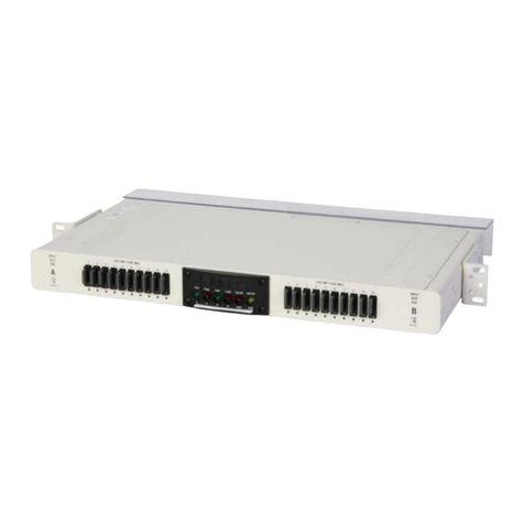
Checkpoint 61000 User manual

23 January 2014
Getting Started Guide
Check Point 61000
Security System
R75.40VS for 61000
Protected

© 2014 Check Point Software Technologies Ltd.
All rights reserved. This product and related documentation are protected by copyright and distributed under
licensing restricting their use, copying, distribution, and decompilation. No part of this product or related
documentation may be reproduced in any form or by any means without prior written authorization of Check
Point. While every precaution has been taken in the preparation of this book, Check Point assumes no
responsibility for errors or omissions. This publication and features described herein are subject to change
without notice.
RESTRICTED RIGHTS LEGEND:
Use, duplication, or disclosure by the government is subject to restrictions as set forth in subparagraph
(c)(1)(ii) of the Rights in Technical Data and Computer Software clause at DFARS 252.227-7013 and FAR
52.227-19.
TRADEMARKS:
Refer to the Copyright page (http://www.checkpoint.com/copyright.html) for a list of our trademarks.
Refer to the Third Party copyright notices (http://www.checkpoint.com/3rd_party_copyright.html) for a list of
relevant copyrights and third-party licenses.

Important Information
Latest Software
We recommend that you install the most recent software release to stay up-to-date with the latest functional
improvements, stability fixes, security enhancements and protection against new and evolving attacks.
Latest Documentation
The latest version of this document is at:
(http://supportcontent.checkpoint.com/documentation_download?ID=20444)
To learn more, visit the Check Point Support Center (http://supportcenter.checkpoint.com).
For more about this release, see the R75.40VS for 61000 home page
(https://supportcenter.checkpoint.com/supportcenter/portal?eventSubmit_doGoviewsolutiondetails=&solutio
nid=sk89900).
Revision History
Date
Description
23 January 2014
Added Health and Safety Information in French ("Informations
relatives à la santé et à la sécurité" on page 6).
Improved formatting and document layout.
Added SGM240 LEDs support information.
16 September 2013
Added: After configuring a Security Gateway, verify the
configuration by running asg diag ("Confirming the Security
Gateway Software Configuration" on page 54).
9 July 2013
Corrected syntax of asg monitor command ("Monitoring
Chassis and Component Status (asg monitor)" on page 61).
Corrected examples of asg search command ("Searching
for a Connection (asg search)" on page 70).
21 March 2013
Added: Before creating the VSX Gateway, if the management
interface is not eth1-Mgmt4, see sk92556 ("Configuring a VSX
Gateway" on page 54).
10 February 2013
First release of this document.
Feedback
Check Point is engaged in a continuous effort to improve its documentation.
Please help us by sending your comments
(mailto:cp_techpub_feedback@checkpoint.com?subject=Feedback on R75.40VS Check Point 61000
Security System Getting Started Guide).

Health and Safety Information
Check Point Chassis Security System Getting Started Guide R75.40VS for 61000 | 4
Health and Safety Information
Read these warnings before setting up or using the appliance.
Warning -
Do not block air vents. This is to ensure sufficient airflow for the individual SGMs in
the Chassis.
This appliance does not contain any user-serviceable parts. Do not remove any
covers or attempt to gain access to the inside of the product. Opening the device or
modifying it in any way has the risk of personal injury and will void your warranty.
The following instructions are for trained service personnel only.
Handle SGM system parts carefully to prevent damage. These measures are sufficient to protect your
equipment from static electricity discharge:
When handling components (Fans, CMMS, SGMS, PSUs, SSMs) use a grounded wrist-strap designed
for static discharge elimination.
Touch a grounded metal object before removing the board from the anti-static bag.
Hold the board by its edges only. Do not touch its components, peripheral chips, memory modules or
gold contacts.
When holding memory modules, do not touch their pins or gold edge fingers.
Restore SGMs to the anti-static bag when they are not in use or not installed in the Chassis. Some
circuitry on the SGM can continue operating after the power is switched off.
Do not let the lithium battery cell (used to power the real-time clock on the CMM) short. The battery can
heat up and become a burn hazard.
Warning -
DANGER OF EXPLOSION IF BATTERY IS INCORRECTLY REPLACED.
REPLACE ONLY WITH SAME OR EQUIVALENT TYPE RECOMMENDED BY
CHECK POINT SUPPORT.
DISCARD USED BATTERIES ACCORDING TO INSTRUCTIONS FROM CHECK
POINT.
Do not operate the processor without a thermal solution. Damage to the processor can occur in
seconds.
Before you install or remove a chassis, or work near power supplies, turn off the power and unplug the
power cord.
For California:
Perchlorate Material - special handling can apply. See http://www.dtsc.ca.gov/hazardouswaste/perchlorate
The foregoing notice is provided in accordance with California Code of Regulations Title 22, Division 4.5,
Chapter 33. Best Management Practices for Perchlorate Materials. This product, part, or both may include a
lithium manganese dioxide battery which contains a perchlorate substance.
Proposition 65 Chemical
Chemicals identified by the State of California, pursuant to the requirements of the California Safe Drinking
Water and Toxic Enforcement Act of 1986, California Health & Safety Code s. 25249.5, et seq. ("Proposition
65"), that is "known to the State to cause cancer or reproductive toxicity" (see http://www.calepa.ca.gov)
WARNING:
Handling the cord on this product will expose you to lead, a chemical known to the State of California to
cause cancer, and birth defects or other reproductive harm. Wash hands after handling.

Health and Safety Information
Check Point Chassis Security System Getting Started Guide R75.40VS for 61000 | 5
Federal Communications Commission (FCC) Statement:
Note: This equipment has been tested and found to comply with the limits for a Class A digital device,
pursuant to Part 15 of the FCC Rules. These limits are designed to provide reasonable protection against
harmful interference when the equipment is operated in a commercial environment. This equipment
generates, uses, and can radiate radio frequency energy and, if not installed and used in accordance with
the instruction manual, may cause harmful interference to radio communications. Operation of this
equipment in a residential area is likely to cause harmful interference in which case the user will be required
to correct the interference at his own expense.
Information to user:
The user's manual or instruction manual for an intentional or unintentional radiator shall caution the user that
changes or modifications not expressly approved by the party responsible for compliance could void the
user's authority to operate the equipment. In cases where the manual is provided only in a form other than
paper, such as on a computer disk or over the Internet, the information required by this section may be
included in the manual in that alternative form, provided the user can reasonably be expected to have the
capability to access information in that form.
Canadian Department Compliance Statement:
This Class A digital apparatus complies with Canadian ICES-003. Cet appareil numérique de la classe A est
conforme à la norme NMB-003 du Canada.
Japan Class A Compliance Statement:
European Union (EU) Electromagnetic Compatibility Directive
This product is herewith confirmed to comply with the requirements set out in the Council Directive on the
Approximation of the Laws of the Member States relating to Electromagnetic Compatibility Directive
(2004/108/EC).
This product is in conformity with Low Voltage Directive 2006/95/EC, and complies with the requirements in
the Council Directive 2006/95/EC relating to electrical equipment designed for use within certain voltage
limits and the Amendment Directive 93/68/EEC.
Product Disposal
This symbol on the product or on its packaging indicates that this product must not be disposed of with your
other household waste. Instead, it is your responsibility to dispose of your waste equipment by handing it
over to a designated collection point for the recycling of waste electrical and electronic equipment. The
separate collection and recycling of your waste equipment at the time of disposal will help to conserve
natural resources and ensure that it is recycled in a manner that protects human health and the
environment. For more information about where you can drop off your waste equipment for recycling, please
contact your local city office or your household waste disposal service.

Informations relatives à la santé et à la sécurité
Check Point Chassis Security System Getting Started Guide R75.40VS for 61000 | 6
Informations relatives à la santé et à
la sécurité
Avant de mettre en place ou d'utiliser l'appareil, veuillez lire ces avertissements.
Avertissement :
Ne pas obturer les aérations. Les SGM dans le châssis doivent disposer d'une
aération suffisante.
Cet appareil ne contient aucune pièce remplaçable par l'utilisateur. Ne pas retirer de
capot ni tenter d'atteindre l'intérieur. L'ouverture ou la modification de l'appareil peut
traîner un risque de blessure et invalidera la garantie. Les instructions suivantes
sont réservées à un personnel de maintenance formé.
Manipulez avec précautions les pièces du SGM pour ne pas les endommager. Les mesures suivantes sont
suffisantes pour protéger votre équipement contre les décharges d'électricité statique :
Avant de manipuler un composant (ventilateur, CMM, SGM, PSU, SSM), portez au poignet un bracelet
antistatique relié à la terre.
Touchez un objet métallique relié à la terre avant de retirer la carte de son sachet antistatique.
Ne tenez la carte que par ses bords. Ne touchez aucun composant, puce périphérique, module mémoire
ou contact plaqué or.
Lorsque vous manipulez des modules mémoire, ne touchez pas leurs broches ou les pistes de contact
dorées.
Remettez dans leur sachet antistatique les SGM lorsqu'ils ne sont pas utilisés ou installés dans le
châssis. Certains circuits du SGM peuvent continuer de fonctionner même si l'appareil est éteint.
Il ne faut jamais court-circuiter la pile au lithium (qui alimente l'horloge temps-réel du CMM). Elle pourrait
chauffer et déclencher un incendie.
Avertissement :
DANGER D'EXPLOSION SI LA PILE N'EST PAS CORRECTEMENT
REMPLACÉE. NE REMPLACER QU'AVEC UN TYPE IDENTIQUE OU
ÉQUIVALENT, RECOMMANDÉ PAR L'ASSISTANCE CHECKPOINT.
LES PILES DOIVENT ÊTRE MISES AU REBUT CONFORMÉMENT AUX
INSTRUCTIONS DE CHECKPOINT.
Ne pas faire fonctionner le processeur sans refroidissement. Le processeur peut être endommagé en
quelques secondes.
Avant de manipuler une appliance ou ses blocs d’alimentations, l’éteindre et débrancher son câble
électrique.
Pour la Californie :
Matériau perchloraté : manipulation spéciale potentiellement requise. Voir
http://www.dtsc.ca.gov/hazardouswaste/perchlorate
L'avis suivant est fourni conformément au California Code of Regulations, titre 22, division 4.5, chapitre 33.
Meilleures pratiques de manipulation des matériaux perchloratés. Ce produit, cette pièce ou les deux
peuvent contenir une pile au dioxyde de lithium manganèse, qui contient une substance perchloratée.
Produits chimiques « Proposition 65 »
Les produits chimiques identifiés par l'état de Californie, conformément aux exigences du California Safe
Drinking Water and Toxic Enforcement Act of 1986 du California Health & Safety Code s. 25249.5, et seq.
(« Proposition 65 »), qui sont « connus par l'état pour causer le cancer ou être toxiques pour la
reproduction » (voir http://www.calepa.ca.gov)

Informations relatives à la santé et à la sécurité
Check Point Chassis Security System Getting Started Guide R75.40VS for 61000 | 7
AVERTISSEMENT :
La manipulation de ce cordon vous expose au contact du plomb, un élément reconnue par l'état de
Californie pour causer de cancer, des malformations à la naissance et autres dommages relatifs à la
reproduction. Se laver les mains après toute manipulation.
Déclaration à la Federal Communications Commission (FCC) :
Remarque : Cet équipement a été testé et déclaré conforme aux limites pour appareils numériques de
classe A, selon la section 15 des règlements de la FCC. Ces limitations sont conçues pour fournir une
protection raisonnable contre les interférences nocives dans un environnement commercial. Cet
appareil génère, et peut diffuser des fréquences radio et, dans le cas d’une installation et d’une utilisation
non conformes aux instructions, il peut provoquer des interférences nuisibles aux communications radio. Le
fonctionnement de cet équipement dans une zone résidentielle engendrera vraisemblablement des
perturbations préjudiciables, auquel cas l’utilisateur sera tenu d’éliminer ces perturbations à sa charge.
Information à l'intention de l'utilisateur :
Le manuel utilisateur ou le manuel d'instruction d'un dispositif rayonnant (intentionnel ou non) doit avertir
que toute modification non approuvée expressément par la partie responsable de la conformité peut annuler
le droit de faire fonctionner l'équipement. Si le manuel n'est pas fourni sous forme imprimée (par exemple
sur le disque d'un ordinateur ou via Internet), les informations requises par cette section doivent être
incluses dans ces versions du manuel, sous réserve que l'utilisateur soit raisonnablement capable d'y
accéder.
Déclaration de conformité du département canadien :
This Class A digital apparatus complies with Canadian ICES-003. appareil numérique de la classe A est
conforme à la norme NMB-003 du Canada.
Déclaration de conformité de classe A pour le Japon :
Directive de l'Union européenne relative à la compatibilité électromagnétique
Ce produit est certifié conforme aux exigences de la directive du Conseil concernant concernant le
rapprochement des législations des États membres relatives à la directive sur la compatibilité
électromagnétique (2004/108/CE).
Ce produit est conforme à la directive basse tension 2006/95/CE et satisfait aux exigences de la directive
2006/95/CE du Conseil relative aux équipements électriques conçus pour être utilisés dans une certaine
plage de ensions, selon les modifications de la directive 93/68/CEE.
Mise au rebut du produit
Ce symbole apposé sur le produit ou son emballage signifie que le produit ne doit pas être mis au rebut
avec les autres déchets ménagers. Il est de votre responsabilité de le porter à un centre de collecte désigné
pour le recyclage des équipements électriques et électroniques. Le fait de séparer vos équipements lors de

Informations relatives à la santé et à la sécurité
Check Point Chassis Security System Getting Started Guide R75.40VS for 61000 | 8
la mise au rebut, et de les recycler, contribue à préserver les ressources naturelles et s'assure qu'ils sont
recyclés d'une façon qui protège la santé de l'homme et l'environnement. Pour obtenir plus d'informations
sur les lieux où déposer vos équipements mis au rebut, veuillez contacter votre municipalité ou le service de
gestion des déchets.

Contents
Important Information............................................................................................................ 3
Health and Safety Information .............................................................................................. 4
Informations relatives à la santé et à la sécurité................................................................. 6
Introduction.......................................................................................................................... 11
Overview of Check Point 61000 Security Systems ............................................................ 11
Check Point Virtual Systems ............................................................................................. 11
In this Document ............................................................................................................... 13
Shipping Carton Contents.................................................................................................. 13
Hardware Components........................................................................................................ 14
61000 Security System Front Panel Modules.................................................................... 14
Security Switch Module (SSM) .......................................................................................... 16
SSM160 Security Switch Module.................................................................................. 17
SSM60 Security Switch Module.................................................................................... 18
Security Switch Module LEDs....................................................................................... 19
Security Gateway Module (SGM) ...................................................................................... 20
SGM260 LEDs.............................................................................................................. 20
SGM SGM220 LEDs..................................................................................................... 22
AC Power Supply Units (PSUs)......................................................................................... 23
AC Power Cords................................................................................................................ 24
DC Power Entry Modules (PEMs)...................................................................................... 26
PEM Panel and LED Indicators..................................................................................... 26
Fan Trays.......................................................................................................................... 27
Chassis Management Modules.......................................................................................... 27
Blank Filler Panels for Airflow Management ...................................................................... 29
Front Blank Panels with Air Baffles............................................................................... 29
Step 1: Site Preparation....................................................................................................... 30
Rack Mounting Requirements ........................................................................................... 30
Required Tools.................................................................................................................. 30
Step 2: Installing the Chassis in a Rack............................................................................. 31
Step 3: Installing Components and Connecting Power Cables........................................ 32
Inserting AC Power Supply Units....................................................................................... 32
Inserting Fan Trays............................................................................................................ 33
Inserting Chassis Management Modules........................................................................... 34
Inserting Security Switch Modules..................................................................................... 35
Inserting Security Gateway Modules ................................................................................. 36
Inserting Transceivers....................................................................................................... 37
Inserting Twisted Pair Transceivers.............................................................................. 37
Inserting Fiber Optic Transceivers ................................................................................ 38
Inserting QSFP Splitters ............................................................................................... 39
Inserting Front Blank Panels.............................................................................................. 39
Connecting AC Power Cables........................................................................................... 39
Connecting DC Power....................................................................................................... 39
Connecting a Second Chassis........................................................................................... 41
Step 4: Turning on the 61000 Security System.................................................................. 42
Step 5: Validating Chassis ID on a Dual Chassis Configuration ...................................... 43
Step 6: Software Installation............................................................................................... 44
Before Installing Firmware and Software........................................................................... 44
Installing SSM160 Firmware.............................................................................................. 45
Installing the SGM Image .................................................................................................. 47
Installing the SGM Using snapshot import .................................................................... 47
Installing the SGM Image Using Removable Media ...................................................... 47
Step 7: Connecting to the Network..................................................................................... 49

Step 8: Initial Software Configuration ................................................................................ 50
Connecting a Console....................................................................................................... 50
Working on the Initial Setup............................................................................................... 50
Step 9: SmartDashboard Configuration............................................................................. 53
Configuring a Security Gateway ........................................................................................ 53
Confirming the Security Gateway Software Configuration............................................. 54
Configuring a VSX Gateway.............................................................................................. 54
Wizard Step 1: Defining VSX Gateway General Properties........................................... 55
Wizard Step 2: Selecting Virtual Systems Creation Templates ..................................... 55
Wizard Step 3: Establishing SIC Trust.......................................................................... 55
Wizard Step 4: Defining Physical Interfaces.................................................................. 56
Wizard Step 5: Virtual Network Device Configuration.................................................... 56
Wizard Step 6: VSX Gateway Management.................................................................. 56
Wizard Step 7: Completing the VSX Wizard ................................................................. 56
Confirming the VSX Gateway Software Configuration................................................... 57
Basic Configuration Using gclish....................................................................................... 58
Licensing and Registration................................................................................................. 60
Monitoring and Configuration Commands......................................................................... 61
Showing Chassis and Component State (asg stat)............................................................ 61
Monitoring Chassis and Component Status (asg monitor)................................................. 61
Monitoring Performance Indicators and Statistics (asg perf).............................................. 63
Monitoring Hardware Components (asg hw_monitor)........................................................ 64
Monitoring SGM Resources (asg resource)....................................................................... 68
Searching for a Connection (asg search)........................................................................... 70
Configuring Alerts for SGM and Chassis Events (asg alert)............................................... 71
Monitoring the System using SNMP .................................................................................. 73
SNMP in a VSX Gateway ............................................................................................. 73
Troubleshooting Commands .............................................................................................. 75
Collecting System Diagnostics (asg diag).......................................................................... 75
Error Types................................................................................................................... 79
Changing Compliance Thresholds................................................................................ 79

Introduction
Check Point Chassis Security System Getting Started Guide R75.40VS for 61000 | 11
Introduction
Thank you for choosing Check Point’s 61000 Security System. We hope that you will be satisfied with this
system and our support services. Check Point products supply your business with the most up to date and
secure solutions available today.
Check Point also delivers worldwide technical services including educational, professional and support
services through a network of Authorized Training Centers, Certified Support Partners and Check Point
technical support personnel to ensure that you get the most out of your security investment.
For additional information on the Internet Security Product Suite and other security solutions, refer to the
Check Point Web site (http://www.checkpoint.com), or call Check Point at 1(800) 429-4391. For additional
technical information about Check Point products, consult the Check Point Support Center
(http://supportcenter.checkpoint.com).
Welcome to the Check Point family. We look forward to meeting all of your current and future network,
application and management security needs.
Overview of Check Point 61000 Security Systems
The Check Point 61000 Security System is a high performance, scalable, carrier class solution for Service
Providers and high-end data centers. The system gives advanced Security Gateway functionality to meet
your dynamically changing security needs. Supported Security Gateway Software Blades include: Firewall,
IPS, Application Control, Identity Awareness, URL Filtering, IPSec VPN, Anti-Bot, and Anti-Virus.
The Check Point 61000 Security System is a 14-15U Chassis and includes:
Component(s)
Function
Up to 12 Security Gateway Modules
(SGMs)
Runs a high performance Firewall, and other
Software Blades.
2 Security Switch Modules (SSMs)
Distributes network traffic to SGMs.
2 Chassis Management Modules (CMMs)
Monitors the Chassis, the SSMs and the SGMs with
zero downtime.
The 61000 Security System:
Is highly fault tolerant, and provides redundancy between Chassis modules, power supplies and fans.
For extra redundancy, you can install a Dual Chassis deployment.
Has NEBS-ready and Non-NEBS versions. The Network Equipment Building Systems (NEBS) certificate
ensures that 61000 Security System meets the environmental and spatial requirements for products
used in telecommunications networks.
Includes a rich variety of CLI monitoring and management tools. The system can be centrally managed
from Check Point Security Management Server or a Multi-Domain Security Management.
Lets you install different numbers of SGMs to match the processing needs of your network.
You can operate the 61000 Security System as a Security Gateway or as a VSX Gateway for Check Point
Virtual Systems.
Check Point Virtual Systems
With Check Point Virtual Systems you can consolidate infrastructure by creating multiple virtualized security
gateways on the 61000 Security System, delivering deep cost savings, seamless security and infrastructure
consolidation. Based on proven virtualized security design and the extensible Software Blade Architecture,
Virtual Systems provide best-in-class customized security protections to multiple networks and simplify
enterprise-wide policy by creating tailored policies for each network.

Introduction
Check Point Chassis Security System Getting Started Guide R75.40VS for 61000 | 12
Administrators can replicate conventional physical security gateways with Virtual Systems to deliver
advanced protection to multiple networks and network segments. Up to 250 fully independent Virtual
Systems can be supported on the 61000 Security System, delivering scalability, availability and performance
while dramatically reduce hardware investment, space requirements and maintenance costs. The latest
Check Point technologies ensure the best performance for virtualized security; CoreXL technology utilizes
multi-core processors to increase throughput, 64-bit Gaia OS allows a significantly increased number of
concurrent connections.
Complete virtualization of network infrastructure allows easy deployment and configuration of network
topology with simpler inter-VS communication. Save the costs of external network routers and switches by
using integrated virtual routers, switches and links to direct traffic to their intended destinations.
KEY FEATURES
Consolidate up to 250 gateways in a single device
Software Blade Architecture
Gaia 64-bit operating system
Separation of management duties
Customized security policies per Virtual System
Per Virtual System Monitoring of resource usage
KEY BENEFITS
Easily add virtual systems to a security gateway
Reduce hardware cost and simplified network policy by consolidating multiple gateways into a single
device
Stronger performance and manageability enable enterprises to better leverage their investment
More granularity and greater manageability with customizable policies per Virtual System
Better usage-based resource planning with per Virtual System monitoring
Boost performance with Multi-core CoreXL technology

Introduction
Check Point Chassis Security System Getting Started Guide R75.40VS for 61000 | 13
In this Document
A brief overview of necessary 61000 Security System concepts and features
A step by step guide to getting the 61000 Security System up and running
Note - Screen shots in this guide may apply only to the highest model
to which this guide applies.
Shipping Carton Contents
This section describes the contents of the shipping carton.
Item
Description
Check Point 61000 Security
System
A single 61000 Security System Chassis
61000 Security System
components
2 to 12 Security Gateway Modules
2 Security Switch Modules
2 Chassis Management Modules
Power Supplies (preinstalled)
5 AC Power Supply Units (PSUs) or
1 to 2 DC Power Entry Modules (PEMs)
6 Fans (preinstalled)
Power cord set
Documentation
EULA
Welcome document
Obligatory Hardware Purchases
Transceivers are not included in the shipping carton and must be purchased separately.
SSM60 Transceivers
Ports
Required Transceivers
Network and Synchronization
Fiber transceiver for 10GbE XFP ports (SR/LR)
Management and log
Fiber transceiver for 1GbE SFP ports (SX/LR)
Twisted-pair transceiver for 1GbE SFP ports
Fiber transceiver for 10GbE XFP ports (SR/LR)
SSM160 Transceivers
Ports
Required Transceivers
Network and Synchronization
SFP+ (10GbE) Fiber transceiver for SFP+ ports (SR/LR)
SFP (1GbE) Fiber transceiver for SFP+ ports (SX/LX)
Twisted pair (1GbE) transceiver for SFP+ ports
QSFP transceiver for 40GbE ports (SR/LR)
QSFP splitter for 40GbE ports

Hardware Components
Check Point Chassis Security System Getting Started Guide R75.40VS for 61000 | 14
Ports
Required Transceivers
Management and log
Fiber/Twisted pair transceiver for 1GbE SFP+ ports (SX/LX)
SFP+ (10GbE) Fiber transceiver for SFP+ ports (SR/LR)
Hardware Components
This section is about the hardware components of the 61000 Security System.
61000 Security System Front Panel Modules
Item
Description
1
The Security Gateway Modules (SGMs) in the Chassis work together as a single, high
performance Security Gateway or VSX Gateway. Adding a Security Gateway Module scales
the performance of the system. A Security Gateway Module can be added and removed
without losing connections. If an SGM is removed or fails, traffic is distributed to the other
active SGMs.
Security Gateway Module slots are numbered 1 to 12, left to right. Slot 7 for example,
(labeled [7] in the diagram) is the slot that is immediately to the right of the two Security
Switch Module slots.

Hardware Components
Check Point Chassis Security System Getting Started Guide R75.40VS for 61000 | 15
Item
Description
2
Console port, for a serial connection to a specific SGM using a terminal emulation program.
3
USB port, for a connection to external media, such as a DVD drive.
4
The Security Switch Module (SSM) distributes network traffic to the Security Gateway
Modules and forwards traffic from the Security Gateway Modules. Two are inserted in a
chassis. Two SSM versions are available:
SSM60
Not supported in a VSX Gateway
Not supported for SGM240
SSM160
For more about each port, see Security Switch Module Ports ("Security Switch Module
(SSM)" on page 16).
5
The Chassis Management Module (CMM) monitors the status of the chassis hardware
components. It also supplies the DC current to the cooling fan trays.
If the Chassis Management Module fails or is removed from the chassis, the 61000 Security
System continues to forward traffic. However, hardware monitoring is not available. Adding
or removing a Security Gateway Module to or from the chassis is not recognized. if the two
CMMs are removed, the cooling fans stop working.
Warning - There must be at least one CMM in the chassis.
A second Chassis Management Module can be used to supply CMM High Availability.
In the CLI output, the lower slot is listed bay 1. The upper slot is listed as bay2.
6
Power:
AC Power Supply Units (PSUs)
100 VAC to 240 VAC
3-5 PSUs
Or:
DC Power Entry Modules (PEMs)
48 VDC to 60 VDC
2 PEMs
Field-replaceable and hot-swappable
In the CLI output:
Upper slots are for DC PEMs. They are listed as bay 1 and bay 2, numbered right to
left.
Lower slots are for AC PSUs. They are listed as bay 1 to bay 5, numbered right to left.

Hardware Components
Check Point Chassis Security System Getting Started Guide R75.40VS for 61000 | 16
Security Switch Module (SSM)
The Security Switch Module (SSM) distributes network traffic to the Security Gateway Modules and forwards
traffic from the Security Gateway Modules. Two are inserted in a chassis. Two SSM versions are available:
SSM60
Not supported in a VSX Gateway
Not supported for SGM240
SSM160

Hardware Components
Check Point Chassis Security System Getting Started Guide R75.40VS for 61000 | 17
SSM160 Security Switch Module
Security Switch Modules
Item
Description
(1)
1 port for direct access through LAN
1 port for direct access through console (serial)
(2)
2 x 40GbE QSFP data ports.
In the initial setup program, the interface names
are:
Left Security Switch Module:
eth1-09, eth1-13
Right Security Switch Module:
eth2-09, eth2-13
Use a QSFP splitter to split each of the two QSFP
ports to 4 x 10GbE.
When using a QSFP splitter the interface names
are:
Left Security Switch Module upper QSFP port:
eth1-09 to eth1-12
Left Security Switch Module lower QSFP port:
eth1-13 to eth1-16
Right Security Switch Module upper QSFP port:
eth2-09 to eth2-12
Right Security Switch Module lower QSFP port:
eth2-13 to eth2-16
(3)
7 x 10GbE SFP+ data ports
Can use 1GbE or 10GbE transceivers
In the initial setup program, the interface names
are:
Left Security Switch Module:
eth1-01, eth1-02, ... eth1-07
Right Security Switch Module:
eth2-01, eth2-02, ... eth2-07
In SmartDashboard, define used interfaces as
internal or external.
(4)
1 synchronization port for connecting to and
synchronizing with another 61000 appliance that
functions as a high availability peer.
10 GbE SFP+ port
Interface names are eth1-Sync in the left and
eth2-sync on the right.
(5)
Management and logging ports. Connect these ports to
the management/logging network. Security
Management Server or dedicated logging servers
should be accessible from these interfaces.
2x 10GbE SFP+ port
In the 61000 appliance initial setup program, these
interfaces are labeled:
On the left SSM: eth1-Mgmt1, eth1-Mgmt2
On the right SSM: eth2-Mgmt1, eth2-
Mgmt2

Hardware Components
Check Point Chassis Security System Getting Started Guide R75.40VS for 61000 | 18
(6)
Management and logging ports. Connect these ports to
the management/logging network. Security
Management Server or dedicated logging servers
should be accessible from these interfaces.
2 x 1GbE SFP port
In the 61000 appliance initial setup program, these
interface are labeled
On the left SSM: eth1-Mgmt3, eth1-Mgmt4
On the right SSM: eth2-Mgmt3, eth2-
Mgmt4
SSM60 Security Switch Module
Security Switch Modules
Item
(1)
5 x 10GbE XFP data ports in each Security Switch
Module. These data ports are the network interfaces
of the 61000 Security System.
In the initial setup program, the interfaces in the
Left Security Switch Module are named:
eth1-01, eth1-02, ... eth1-05
Right Security Switch Module are named:
eth2-01, eth2-02, ... eth2-05
In SmartDashboard, define used interfaces as
internal or external.
(2)
1 synchronization port on each SSM for connecting
to and synchronizing with another 61000 Security
System that functions as a high availability peer.
(3)
4 ports for management and logging on each SSM.
2 Upper ports: 1GbE SFP
2 Lower ports: 10GbE XFP
Connect these ports to the management/logging
network. Security Management Server or dedicated
logging servers should be accessible from these
interfaces.
In the initial setup program, the interfaces are named:
On Left SSM:
eth1-Mgmt1, eth1-Mgmt2, ... eth1-Mgmt4
On the right SSM:
eth2-Mgmt1, eth2-Mgmt2, ... eth2-Mgmt4

Hardware Components
Check Point Chassis Security System Getting Started Guide R75.40VS for 61000 | 19
Security Switch Module LEDs
Item
LED
Status
Description
1
Out of
service
Red
SSM out of service
Off (Normal)
SSM hardware is normal
2
Power
On (Normal)
Power on
Off
Power off
3
Hot-swap
Blue
SSM can be safely
removed
Blue
blinking
SSM is going to Standby
mode. Do not remove
Off (Normal)
SSM is Active. Do not
remove
4
SYN ACT
On (Normal)
Normal operation
Off
N/A
5
Link
On
Link enabled
Yellow
blinking
Link is active
Off
Link is disabled

Hardware Components
Check Point Chassis Security System Getting Started Guide R75.40VS for 61000 | 20
Security Gateway Module (SGM)
The Security Gateway Modules (SGMs) in the Chassis work together as a single, high performance Security
Gateway or VSX Gateway. Adding a Security Gateway Module scales the performance of the system. A
Security Gateway Module can be added and removed without losing connections. If an SGM is removed or
fails, traffic is distributed to the other active SGMs.
These SGM versions are available:
SGM220
SGM220T (for NEBS)
SGM240
The SGM240 has more powerful CPUs and uses a more advanced technology. It also has a different front
panel layout and different LEDs.
SGM260 LEDs
Item
LED
Status
Description
5
Out of
service
Red
SGM out of service
Off (Normal)
SGM hardware is
normal
6
Health
Green
(Normal)
SGM core operating
system is active
Green
blinking
SGM core operating
system is partially
active
Off
SGM operating system
is in standby mode
7
Hot-swap
Blue
SGM can be safely
removed
Blue blinking
SGM is going to
standby mode. Do not
remove
Off (Normal)
SGM is active. Do not
remove
CTRL
Link 1
CTRL
Link 2
SSM1 and
SSM2
management
ports
Yellow
Link enabled
Yellow
blinking
Link is active
Off
Link is disabled
CTRL
SPEED
1
CTRL
SSM1 and
SSM2
management
ports
Yellow
10 Gbps
Green
1 Gbps
Off
100 Mbps
Other manuals for 61000
1
This manual suits for next models
1
Table of contents
Other Checkpoint Security System manuals
Popular Security System manuals by other brands
Axis
Axis 0936-001 20289045 installation guide
brennenstuhl
brennenstuhl BrematicPRO THS 868 01 IP44 Instructions for use

Maple Systems
Maple Systems cMT3108XH Series Installation instruction
BV Security
BV Security DVR-CVI-16CH instructions

GSS
GSS PROFESSIONAL PAVP 4300 Assembly instructions
Young Shin Electronics
Young Shin Electronics 2WSHR LCD user guide
