CHEFOOK GRAVITA PLD 300 Operating instructions

24
SERVICE CENTRE
AUTHORISED DEALER
1
GRAVITA’
PLD 300-330-350
Professional slicer CE
Operating and Maintenance Manual
Ed. 01/2020 - ver. 008
2
INTRODUCTION
This manual has been re-presented to provide the Client with all the information on the machine
and its safety regulations, and also the use and maintenance instructions which permit using the
machine in the best way and maintaining its efficiency throughout time.
This manual must be kept in its entirety until the machine is disposed of.
This manual should be given to personnel in charge of the use and periodic maintenance of the
machine.
INDEX OF CHAPTERS
CHAP. 1 - RECEIVING THE MACHINE page 4
1.1 - PACKAGE
1.2 - CHECKING THE PACKAGE UPON DELIVERY
CHAP. 2 - INSTALLATION page 6
2.1 - UNPACKING
2.2 - POSITIONING
2.3 - ELECTRICAL CONNECTION
2.3.1 - Slicer with single-phase motor
2.3.2 - Slicer with 400 V. three-phase motor.
2.3.3 - Slicer with 230 V. three-phase motor
2.3.4 - Blade rotation direction
2.3.5 - Electrical connection modification
2.4 - PRELIMINARY CHECK
2.4.1 - Cleaning and maintenance of the controls
CHAP. 3 - INFORMATION ON THE MACHINE page 10
3.1 - GENERAL PRECAUTIONS
CHAP. 4 - CONSTRUCTION FEATURES
4.2 - SAFETY DEVICES INSTALLED ON THE MACHINE page 12
4.2.1 - Mechanical safety
4.2.2 - Electrical safety
4.3 - DESCRIPTION OF THE MACHINE
4.4 - OVERALL DIMENSIONS, WEIGHT, FEATURES….
CHAP. 5 - MACHINE USE page 16
5.1 - OPERATIONAL CHECK
5.2 - LOADING AND CUTTING THE PRODUCT
5.3 - SHARPENING THE BLADE
CHAP. 6 - ROUTINE CLEANING page 19
6.1 - GENERALITIES
6.2 - CLEANING THE MACHINE
6.2.1 - Cleaning the goods holder plate
6.2.2 - Cleaning the blade, the blabe cover and the ring
6.2.3 - Cleaning the sliceguard
6.2.4 - Cleaning the sharpener
6.3 - SLIDE GUIDES LUBRICATION
23
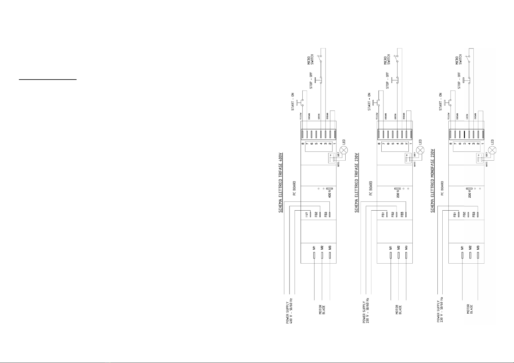
CAP. 9 - ECTRICAL DIAGRAM
9.1 - 115 V. - 230V. SINGLE-PHASE - 230V. THREE-PHASE - 400V. THREE-PHASE
Fig. n°55

22
7.4 - FEEDING CABLE
Periodically check the state of wear and tear of the cable and call the “SERVICE CENTER”
for its replacement.
7.5 - BLADE
Check that the diameter of the blade, after many sharpenings, has not been reduced more
than 10 mm. compared to the original diameter. For its replacement call the “SERVICE
CENTER”.
7.6 - GRINDERS
Check that the grinders continue to have their abrasive property during the sharpening.
When they are no longer abrasive they must be replaced as to not damage the blade,
therefore call the “SERVICE CENTER”.
7.7 - SLIDING GUIDES LUBRICATION
Occasionally put a few drops of oil (from the tube that is provided) on the round bar that the
trolley slides back and forth on, through the hole (OIL) located on the side of the graduated
handgrip.
7.8 - PUSH-BUTTON PANEL
The push-button panel label can be marked and/or consumed with time. In such a case call
the “SERVICE CENTER” to replace it.
CHAP. 8 - DISMANTLING
8.1 - OUT OF SERVICE
If for some reason it is decided to put the machine out of service, make sure that it cannot be
used by anyone: detach or cut the electrical connections.
8.2 - WEEE Waste of Electric and Electronic Equipment
Directive 2002/95/EC, 2002/96/EC and 2003/108/EC on the restriction of the use of
certain hazardous substances in electrical and electronic equipment, and waste
electrical and electronic equipment
This symbol, crossed out wheelie bin, on the product or on its packaging indicates that this
product must not be disposed of with your other household waste.
Separate waste collection of this appliance is organised and managed by the manufacturer.
It is the user’s responsibility to contact the manufacturer and follow the waste treatment
system the manufacturer has adopted for separate waste collection.
The separate collection and recycling of your waste equipment at the time of disposal will
help to conserve natural resources and ensure that it is recycled in a manner that protects
human health and the environment.
(see chap. 4 par. 4.1).
3
CHAP. 7 - MAINTENANCE page 21
7.1 - GENERALITIES
7.2 - BELT
7.3 - FEET
7.4 - FEEDING CABLE
7.5 - BLADE
7.6 - GRINDERS
7.7 - SLIDE GUIDES LUBRICATION
7.8 - PUSH-BUTTON PANEL
CHAP. 8 - DISMANTLING page 22
8.1 - PUTTING OUT OF SERVICE
8.2 - WEEE Waste of Electric and Electronic Equipment
CHAP. 9 - ELECTRICAL DIAGRAM page 23
9.1 - 115 V. - SINGLE-PHASE 230 V. - THREE-PHASE 230 V. -
THREE-PHASE 400 V.

4
CHAP. 1 - RECEIVING THE MACHINE
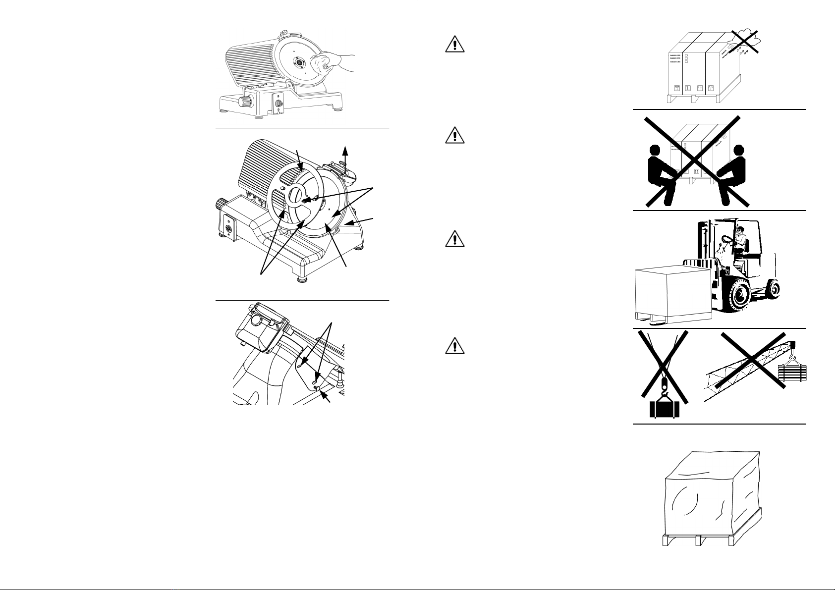
1.1 - PACKAGE
The slicer is shipped in a package which consists of (Fig. n°1): cardboard box, wooden pal-
lets and protective nylon. They should be disposed of separately and according to the norms
in force in the country of installation.
Dimensions
AxBxC
mm
Gross
weight
(Kg)
PLD 300 760x640x700 44
PLD 330 760x640x700 45
PLD 350 760x640x700 46
Do not place more than one of the same
package on top (Fig. n°3).
WARNING!
B
A
C
Fig. n°1
Fig. n°2
Fig. n°3
21
6.2.4 - Cleaning the sharpener
To clean the sharpener it is necessary to
adhere to the following instructions:
1. lift (a) the sharpener up to the top;
2. loosen the knob (1);
3. lift (b) the cup (2) and extract it so that
the knob (1) passes through the larger
opening in the cup (2);
4. rub the grinders with a brush, while
cleaning the other components with
warm water, the equipped detergent or
with neutral detergent (pH 7).
6.3 - SLIDE GUIDES LUBRICATION
The slide guides on the carriage (1-2) must
be lubricated periodically with the equipped
oil (a).
CHAP. 7 - MAINTENANCE
7.1 - GENERALITIES
Before carrying out any maintenance operations it is necessary to:
a) disconnect the feed plug from the electrical network to completely isolate machine from
the rest of the system.
b) bring the graduated handgrip which regulates the thickness gauge to “0”.
7.2 - BELT
The belt does not need to regulated. Generally after 3/4 years it must be replaced, in this
case call the “SERVICE CENTER”.
7.3 - FEET
The feet could deteriorate in time and lose their elasticity, therefore decreasing the stability of
the machine. Replace them by calling the “SERVICE CENTER”.
Fig. n°52
Fig. n°53
a
1
2
Fig. n°54
b
1
2
a
20
1. unhook the blabe cover (Fig. n°48);
2. take out the sharpening device (Fig. n°50
ref.a) and open, by using the graduated
handgrip, the thickness gauge enough to
make the jig (Fig. n°50 ref.b) stick to the
blade;
3. unscrew the three or four screws i (Fig.
n°50 ref.f), depending on the model,
which fasten the blade;
4. rest the jig (b) on the blade, so that the
split in the jig fits in the ring (Fig. n°48
ref.c);
5. match the axes of the two holes (Fig. n°
50 ref.d) on the blade with the twoknobs
(Fig. n°50 ref.e) on the jig, simply making
the blade turn to the desired position;
6. screw the two knobs (e) without
excessively tightening them.
N.B. The blabe cover must be cleaned
with warm water, the equipped
detergente or with neutral detergent (pH
7).
6.2.3 - Cleaning the sliceguard
(Fig. n°51)
To remove the sliceguard simply grasp the
handgrip (1) and pull up so that the two pins
unhook (2), and then extract the sliceguard.
At this point clean the sliceguard with warm
water, the equipped detergent or with neutral
detergent (pH 7).
Fig. n°49
Fig. n°50
a
d
f
b
e
c
Fig. n°51
2
1
5
When the package is received, if there is no
external damage proceed to opening it, ma-
king sure that all material is inside. If the
package upon delivery shows signs of tampe-
ring (Fig. n°8), impact or fall, it is necessary
to present the damage to the carrier, and wi-
thin 3 days of the delivery date, indicated on
the documents, make a precise report of the
damage. Do not overturn the package!!
1.2 - CHECKING THE PACKAGE UPON DELIVERY
Heavy package. Do not lift manually unless
with help of at least three people (Fig. n°5).
Move the package only by electrical trolleys
or manually, equipped with lifting straps (Fig.
n°6).
Do not expose the package to humidity or
rain (Fig. n°4).
Since the center of gravity is not in the middle
of the package, moving it suspended by
chords or similar systems is not advisable
(Fig. n°7).
Fig. n°4
Fig. n°6
Fig. n°5
Fig. n°8
Fig. n°7

6
When transporting it make sure that it is firmly held by the four corners (keeping it pa-
rallel to the floor).
All operations must be carried out by speciali-
zed personnel (Fig. n°9).
WARNING!
2.1 - UNPACKING
Remove the straps from the package (Fig. n°
10) and lift the cardboard (h).
The package should be:
a) the machine on the pallet (Fig. n°11 detail
a);
b) blade extractor (Fig. n°11 detail e);
c) 4 feet (Fig. n°11 detail f);
d) Case, if present (Fig. n°11 detail b).
Check inside the suitcase if it present, find
the following components:
(Fig. n°11):
1. Instruction booklet (detail d) ;
2. CE compliance certificate (detail c);
3. Audio-visual cassette;
4. Liquid detergent with sprayer;
5. Oil tube;
6. Sharpening and burring grinders;
7. Socket wrench to remove grinders;
8. Grinders brush;
9. Large and small screwdrivers;
10. Pliers.
CHAP. 2 - INSTALLATION
Fig. n°9
Fig. n°10
h
a b
Fig. n°11
c
d
e f
19
CHAP. 6 - ROUTINE CLEANING
6.1 - GENERALITIES
Cleaning the machine must be carried out at least once a day or, if necessary, more fre-
quently .
All the parts of the slicer that come in direct or indirect contact with the food to be cut must
be scrupulously cleaned.
The slicer must not be cleaned with water cleaning machines or water jets, but with the pro-
duct provided and/or with neutral detergents (pH 7). The use of any other detergent is
prohibited. Utensils, brushes and whatever else could damage the machine surface must
not be used.
Before carrying out any cleaning operation it is necessary to:
1. disconnect the plug from the electrical network to completely isolate the machine from
the rest of the system;
2. Bring the graduated handgrip which regulates the thickness gauge to “0”.
WARNING: Be careful of residual risks from sharp and/or pointed parts.
6.2 - CLEANING THE MACHINE
6.2.1 - Cleaning the goods holder plate
The trolley (plate + arm + stem) is easily
transportable:
- bring the graduated handgrip to
“0” (1 Fig. n°46);
- bring the trolley (2) to the end of its run (a)
from the controls side; partially unscrew
the plate lock handgrip (3), pull the trolley
towards the operator; completely unscrew
the plate lock handgrip, therefore lift the
trolley up (b - Fig. n°46);
- having taken off the trolley, the goods
holder plate can be carefully cleaned with
warm water, the equipped detergent or
neutral detergent (pH 7) Fig. n°47.
6.2.2 - Cleaning the blade, the blabe
cover and the ring
WARNING: a pair of metallic gloves must
be worn while cleaning the blade (1) (Fig.
n°48) ed utilizzando un panno umido.and
a damp cloth must be used.
Unscrew the handgrip from the bladecover tie
rod (1) and extract the bladecover (2) using
the proper grip to hold it (Fig. n°48). At this
point it is possible to clean the blade a Fig. n°
49.
To clean the surfaces opposite the
blade and the ring, the blade must be
extracted in the following way:
Fig. n°46
1
a
3
b
2
pH
Fig. n°47
Fig. n°48
3
2
1
18
5.3 - SHARPENING THE BLADE
1. disinsert the plug from the outlet and
carefully clean the blade with denatured
alcohol so it is degreased;
2. lift (a) the sharpener (1) and turn it 180°
(b Fig. n°43);
WARNING: Before starting to sharpen the blade, pay attention to RESIDUAL RISKS
(chapter 4.2.2) concerning the dangers of cutting without having followed the in-
structions listed below.
To sharpen the blade, which needs to be done periodically as soon a decrease in cutting is
noticed, the following directions must be adhered to:
3. let it go in a way that the sharpener (c)
fits on the locator pins (d Fig. n°43);
4. check also that the blade stays between
the two grinders;
5. insert the pin and start the machine, by
pressing the “ON” push-button;
6. press the push-button (2 Fig.n°44), let
the blade rotate in contact with the grin-
der for about 30/40 sec. so that a slight
burr forms on the blade edge;
7. press the 2 push-buttons (1 and 2) con-
temporaneously for 3/4 sec. and release
them in the same instant (Fig. n°45);
8. after having completed the sharpening it
is advisable to clean the grinders and the
blade (chapter 6.2.3);
9. once the operation is finished, replace
the sharpening device in its original
position, doing the procedure in reverse.
Fig. n°42
Fig. n°43
c
d
1
b
a
2
Fig. n°45
3
2
Fig. n°44
N.B.: Do not carry on the deburring opera-
tion for more than 1-2 sec. to avoid the
damaging bending of the blade edge.
7
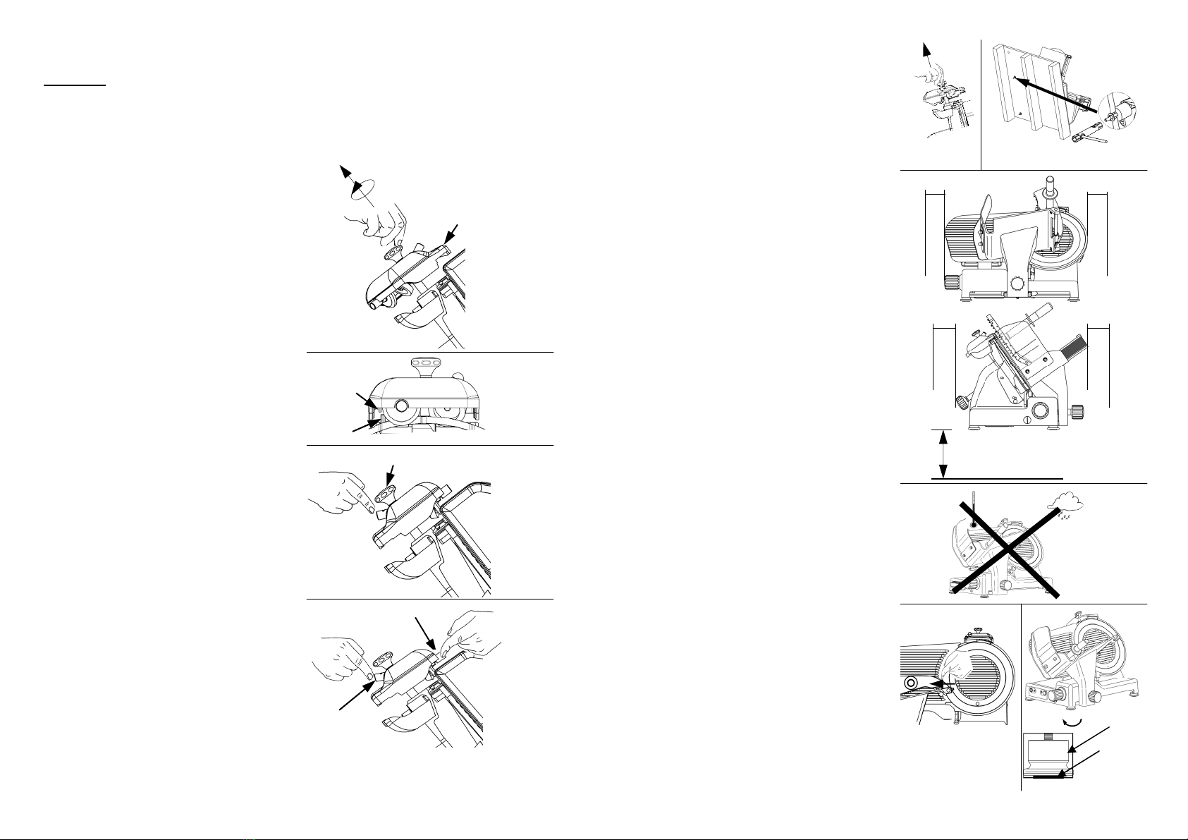
2.2 - POSITIONING
Position the pallet, with the slicer, on a flat
surface and take off (a) the sharpener from
the slicer (Fig. n°12).
At this point turn the machine on its side (Fig.
n°13) and unscrew, with the proper wrench
provided, the 4 nuts which fasten the slicer.
Remove the 4 washers and unscrew the 4
fastening tie rods on the wooden pallet. Take
off the pallet and fasten the 4 feet provided.
Finally, put the sharpener in its place.
Position the slicer in the predestined place.
The dimensions indicated in Tab. 1
(according to the model) must be kept in mind
for the plane where the slicer will be installed,
therefore it must be wide enough, well-
levelled, dry, smooth, robust, stable about 80
cm high off the ground and at least 20 cm
from walls, objects, shelves, etc. (Fig. n°14)
in respect to the space necessary for its use
and safeguarding.
Furthermore the machine must be placed in
an environment with a maximum humidity of
75%, not salty and with a temperature betwe-
en +5°C and +35°C; in any case in environ-
ments which do not lead to deviations of the
above.
Make sure the graduated handgrip is in po-
siion “0”.
Check the alignment of the blade-plane thi-
ckness gauge by running a finger (Fig. n°16)
from the blade towards the thickness gauge
plane (never in the opposite direction). Un-
screw and screw the foot (1) until the correct
alignment is found (Fig. n°17), then screw the
rubber part (2) to fix everything (Fig. n°17).
a
Fig. n°12 Fig. n°13
Fig. n°14
Fig. n°15
Fig. n°16
~ 80cm
20cm
20cm
20cm
20cm
Fig. n°17
1
2
8
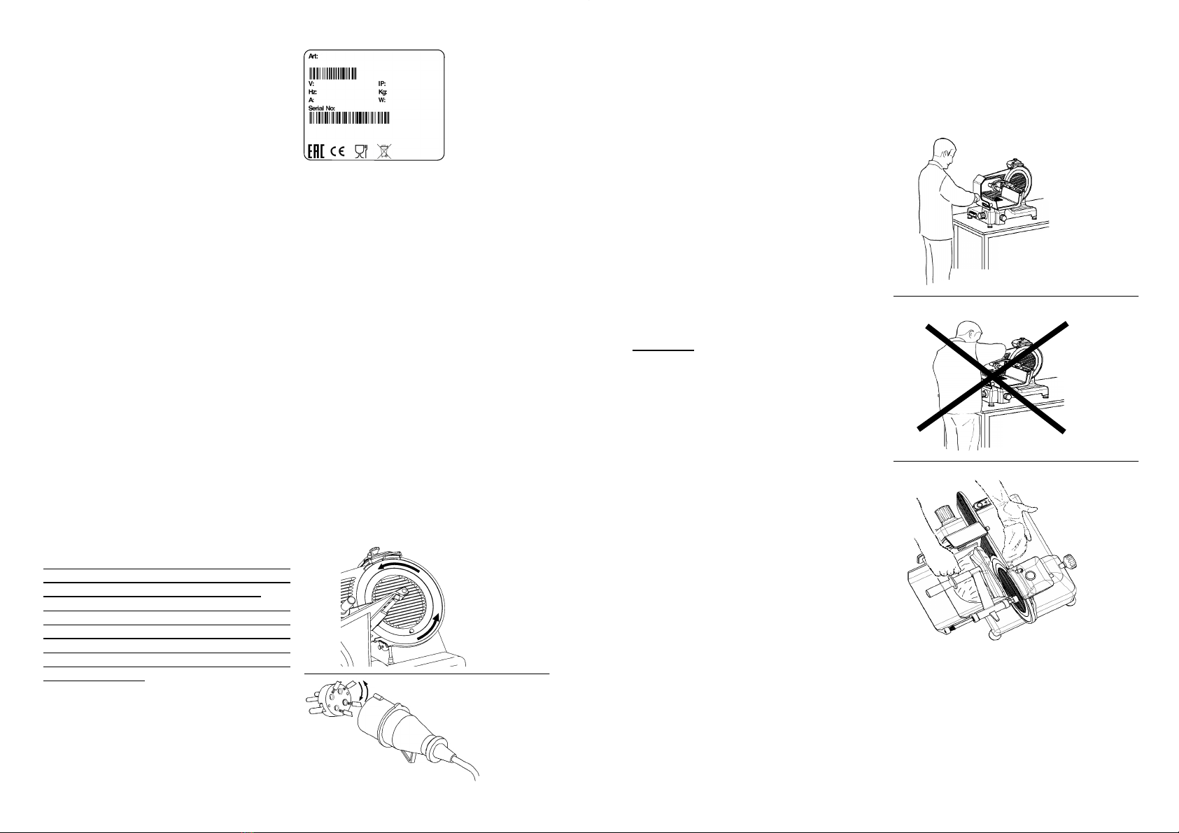
2.3 - ELECTRICAL CONNECTION
Check that the data reported on the techni-
cal-part number plate (Fig. n°18), the delivery
documents and the order, correspond;
contact the supplier for clarification if they do
not.
At this point make sure that the system is
standard and that the cable and grounding
system perfectly operate.
2.3.1 - Slicer with single-phase motor
The slicer is equipped with a feeding cable with a cross section area of 3x1mm²; length
1.5m and a “SHUKO” plug. Connect the 230 V. - 50 Hz slicer, interposing a magnetothermic
differential switch of 10A,= 0.03A.
2.3.2 - Slicer with 400 V. three-phase motor
The slicer is equipped with a feeding cable with a cross section area of 5x1mm², length
1.5m and a red 15A 3F + T CEI plug. Connect the slicer to the 400 V. - 50Hz three-phase
supply mains, interposing a magnetothermic differential switch of 10 A, =0.03A.
2.3.3 - Slicer with 230 V. three-phase motor
The slicer is equipped with a feeding cable with a section area of 5x1mm²; length 1.5m and
a blue 15A 3F + T CEI plug.
Connect the slicer 230 V. - 50 Hz three-phase supply mains, interposing a magnetothermic
differential switch of 10A, I= 0.03A.
Check that the direction of the blade rotation is counter-clockwise looking at the slicer from
the side of the blabe cover. If not proceed as in par. 2.3.4.
2.3.4 - Blade rotation direction
Check the direction of the blade rotation with
a pulse of the “I” push-button (ON), immedia-
tely followed by the “0” push-button OFF.
The direction of the blade rotation must be
counter-clockwise when looking at the slicer
from the blabe cover side (Fig. n°19). In the
case that the rotation direction is not exact,
invert (Fig. n°20) the position of two of the
three phase wires (black, gray or brown) in
the plug.
Fig. n°19
Fig. n°20
Fig. n°18
LEGEND
(A) = Product code and name
(B) = Power supply
(C) = Motor frequency
(D) = Amperage
(E) = Serial number
(F) = Barcode
(G) = Manifacturer
(H) = International Protection
(I) = Weight
(L) = Power
(M) = Origin
(A)
(B)
(C)
(D)
(E)
(H)
(I)
(L)
(F)
(G) (M)
17
5.2 - LOADING AND CUTTING THE PRODUCT
Adhere to the following procedure:
1. Lift the goods presser, load the goods on
the plate, bringing it close to the thi-
ckness gauge, block it with the proper
toothed arm;
2. regulate the desired thickness of the cut
with the graduated handgrip;
3. assume a correct position to avoid acci-
dent: place the right hand on the goods
presser handgrip and, then the left hand
next to the slice guard to take the cut pro-
duct (without touching the blade); the
body must be perpendicular to the work
plane (Fig. n°39).
WARNING: Do not assume positions
which bring body parts in direct contact
with the blade (ex. Fig. n°40);
4. then push the “ON” push-button;
5. push the carriage (plate + goods presser
arm + stem) gently towards the blade,
without applying excessive pressure on
the product with the goods presser arm.
The goods will easily enter the blade, and
the slice guided by the proper sliceguard
will detach and fall on the plane (Fig. n°
40);
6. avoid running the slicer when empty ;
7. at the end of the cutting operation, stop
the machine by putting the switch in the
“OFF” position and put the graduated
handgrip at “0”;
8. after slicing, do not leave the food
lying on the product. Store the food
that has just been sliced in a place
suitable for its preservation;
9. Carry out resharpening the blade as soon
as the cut product has a threaded or
rough surface, therefore the cutting effort
increases (chapter 5.3).
WARNING: The goods to be cut are loaded on the plate only with the graduated handgrip at
“0” and the motor stopped, being careful with the blade and the points.
Fig. n°39
Fig. n°40
Fig. n°41
16
CHAP. 5 - MACHINE USE
5.1 - OPERATIONAL CHECK
For the 1° use follow these instructions:
- check that installation has been carried out
correctly as in chapter 2;
- check that the plate is well fastened with
the lock handgrip (Fig. n°35 ref.1);
- check the sliding of the plate and that it is
free of obstacles on the work counter for all
of its run (Fig. n°36 ref.a);
- check that the goods pressing arm easily
rises and lowers so that it is not impeded
in all its movement (Fig. n°36 ref.b);
- check the opening of the thickness gauge
plane by making the numbered handgrip
turn clockwise and counterclockwise (Fig.
n°37 ref.c);
- check that the sharpener is well fastened
to the machine and that it is easy to extract
and free of obstacles (Fig. n°38 ref.d).
1
Fig. n°35
Fig. n°36
a
b
c
Fig. n°37
Fig. n°38
d
9
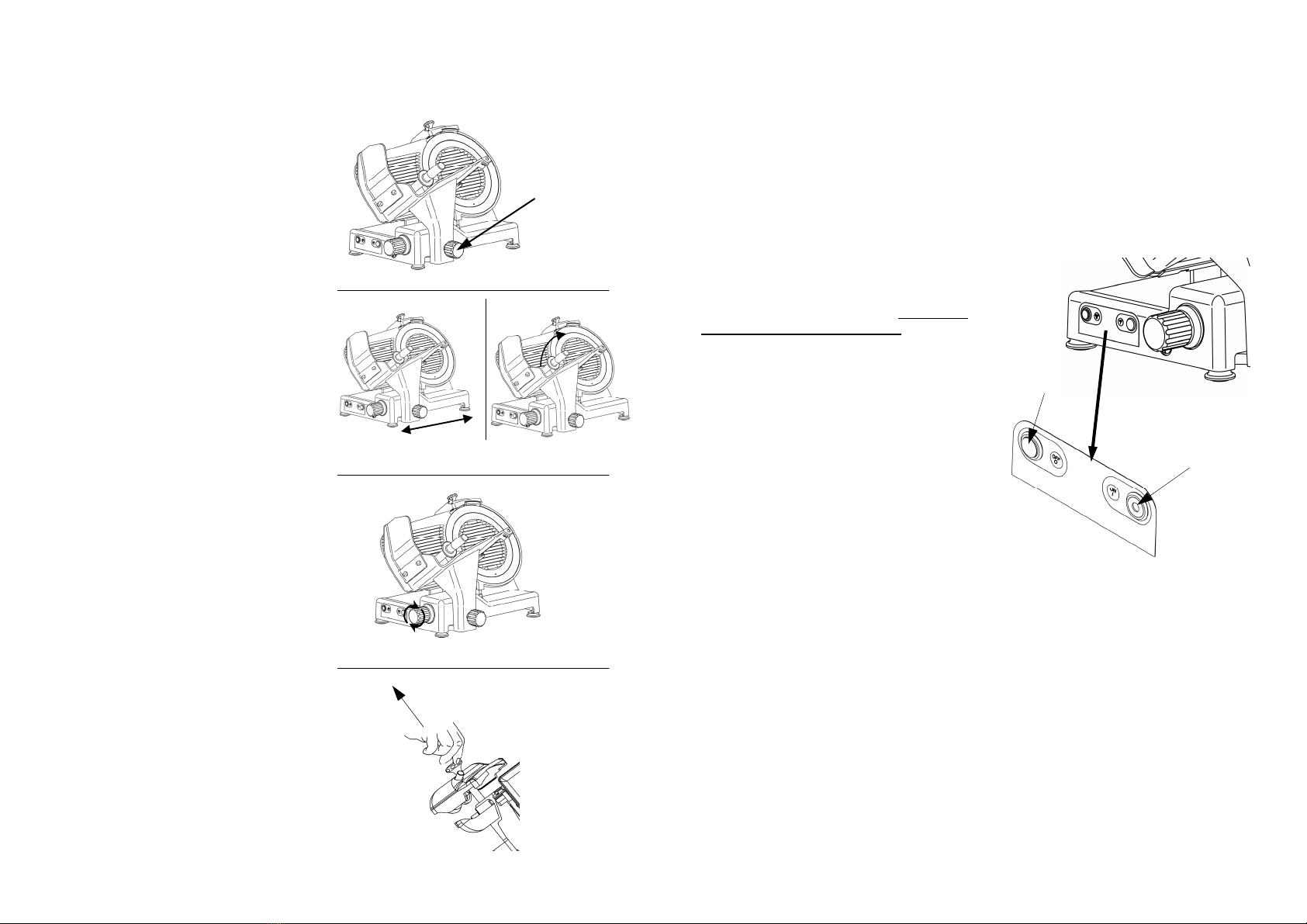
2.3.5 - Electrical connection modification
Unless otherwise specified, the slicers are equipped with 400 V. three-phase connection. To
modify the connection carefully follow these instructions:
- remove the plug from the electric network;
- turn the slicer on the side opposite the trolley;
- take off the yellow cover from the electrical box;
- remove the motor cables from the electronic card;
- connect wires from the motor that have the same colour (white-white, blue-blue, etc.);
- reconnect them to the electronic card;
- check the positioning of the feed selection plugs on the electronic card (Fig. n°21);
- close the box, reposition the slicer and proceed as in par. 2.3.3.
2.4 - PRELIMINARY CHECK
Before testing make sure the goods holder
plate is well-blocked, after which test functio-
ning with the following procedure:
- Push the “ON” push-button and the “OFF”
push-button (Fig. n°22);
- check if by unscrewing the blabe cover tie
rod the machine stops working (Fig. n°30);
- Check if the machine does not start auto-
matically by removing the plug and reinser-
ting it while the machine is running.
Fig. n°22
Push-button
“ON”
Push-button
“OFF” Fig. n°21
2.4.1 - Cleaning and maintenance of the controls
The buttons fitted on this machine are of an extremely high quality standard and can be
washed with water as they have a class IP67 protection rating.
Should they get clogged or jammed after being touched with dirty hands, do not use knives
or sharp tools to try to release them.
WARNING! Pull out the power plug before every cleaning operation, transfer the machine to
an adequate location and spray the buttons with hot water (avoid high-pressure jets).
Be CAREFUL not to let any water penetrate into the other parts of the machine, for reasons
of electrical safety and to preserve the machine’s working life.
This operation should soften the grease and dirt, releasing the button.
Once the buttons have been released, press them several times (with the plug detached) in
order to expel any remaining dirt inside them. If the operation fails from the beginning, repeat
the washing operation several times until the buttons have flushed out all the dirt.
Alternatively, prevent use of the machine and contact the Service Centre to replace the
buttons.
Buttons that have been scratched or tampered with using blunt tools shall not be covered by
the warranty.
10
CHAP. 3 - INFORMATION ON THE MACHINE
3.1 - GENERAL PRECAUTIONS
The general precautions, even though they appear obvious, are fundamental for the installa-
tion, use, maintenance and possible inconveniences with their respective solutions.
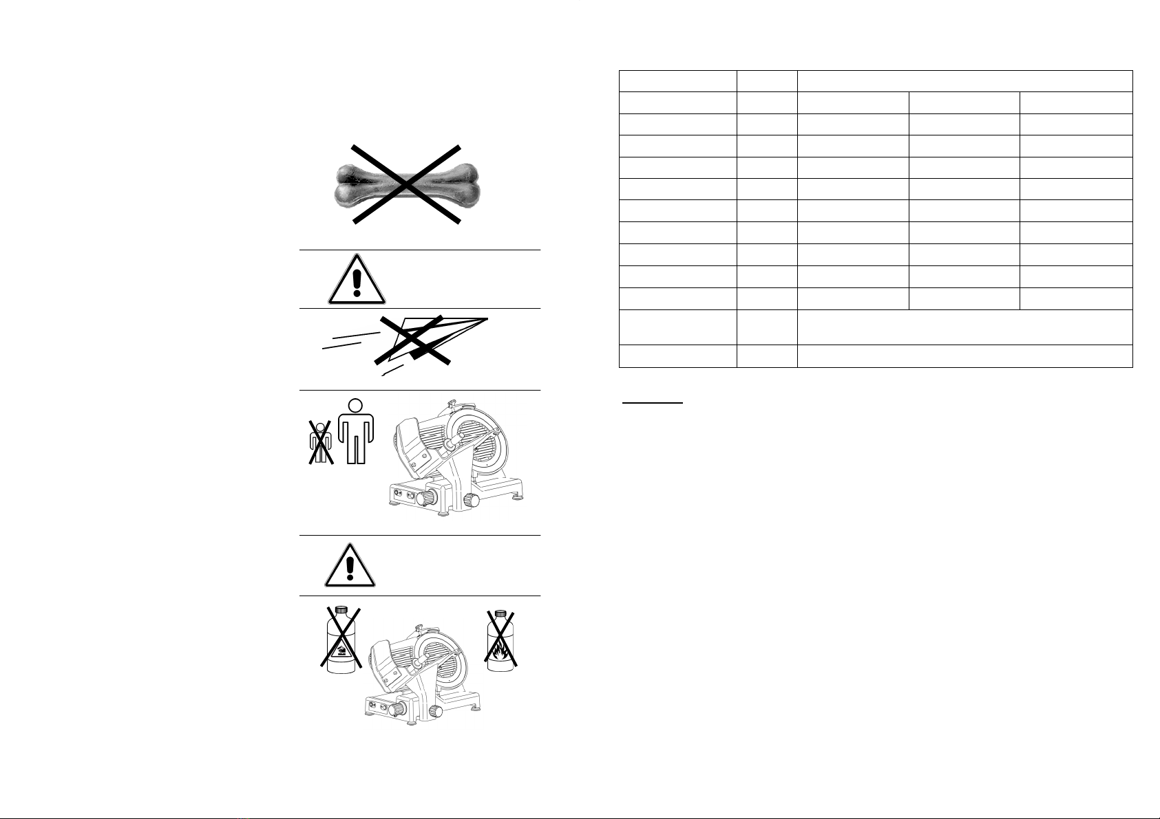
The slicer is designed for cutting fresh, sea-
soned and cooked meats, cured meats and
vegetables, non-frozen and boneless, up to
maximum 20°C (Fig. 23). Any other use
must be regarded as improper and thus
dangerous.
The Manufacturer is not responsible in the
following cases:
the machine is tampered with by u-
nauthorized personnel;
components are substituted with u-
noriginal parts;
the instructions in this manual are
not followed carefully;
the surfaces of the machine are trea-
ted with inappropriate products.
Keep this manual in a safe place for future
information or consultation (Fig. n°24).
The slicer must only be used by trained
personnel who know the safety norms
contained in this manual perfectly.
In the case of an alteration in personnel,
give time for training.
Do not allow the slicer to be used by chil-
dren or by untrained people (Fig. n°25).
Before carrying out any cleaning ormainte-
nance operation, disconnect the machine
plug from the electrical network.
When carrying out routine maintenance or
cleaning of the slicer (and therefore the
guards are removed), carefully evaluate the
residual risks .
During maintenance or cleaning stay
concentrated on the operations.
Do not use corrosive or flammable
substances to clean the slicer (Fig. n°26);
only use the product provided.
WARNING!
Fig. n°23
Fig. n°24
WARNING!
Fig. n°26
Fig. n°25
15
TAB. n°1 - DIMENSION MEASUREMENTS AND TECHNICAL FEATURES
Model U.m. mod. 300 - 330 - 350
Diameter blade mm 300 330 350
Motor Watt/Hp 275/0,37 275/0,37 370/0,50
Cut thickness mm 23 23 23
Run of carriage mm 310 310 310
Hopper mm 305x270 305x270 305x270
A x B mm 465x340 465x340 465x340
C x D x E mm 615x547x465 645x570x455 660x575x455
F x D x G mm 710x547x545 710x570x535 710x575x530
Net weight Kg 35 36 37
Power source 1ph
3ph
230V / 50 Hz
230-400V / 50 Hz
Noise level dB 60
X Y H W mm 270 190 240 220 270 210 260 240 270 225 275 250
WARNING:
The electrical features of the machine are shown on a plate on the back of the machine.

14
Even though the professional CE slicers are equipped with the standard mea-sures for elec-
trical and mechanical protection (both while operating and during cleaning and maintenance),
RESIDUAL RISKS which cannot be completely eliminated in any case exist, highlighted in
this manual under the form of WARNING. They concern the danger of cutting, bruising and
other caused by the blade or by other machine parts.
4.3 - DESCRIPTION OF THE MACHINE
Professional CE slicers have been designed and made by our company with the precise pur-
pose of cutting food products (like salami, meats and vegetables) and they guarantee:
- maximum safety in use, cleaning and maintenance;
- maximum hygiene, thanks to a meticulous selection of materials that come in contact with
the food products, and with the elimination of the edges in the parts of the slicer that come
into contact with the product, in a way that it can be easily and totally cleaned not to men-
tion easily disassembled;
- maximum cutting precision thanks to the cam mechanism;
- all components are robust and stable;
- maximum silence thanks to the belt transmissions;
- very easy to handle.
4.4 - OVERALL DIMENSIONS, WEIGHT, FEATURES ...
Fig. n°34
11
To clean the slicer carefully follow the in-
structions in the chapter: “Routine clea-
ning”.
Do not wash the slicer in a dishwasher
(Fig. n°27) or with water jets, do not
immerge it in water or in other liquids.
Do not leave the slicer exposed to dama-
ging agents: sun, rain, sprays, humidity,
ice (Fig. n°28).
Do not pull the slicer or the feeding cable
(Fig. n°29) to unplug it.
Regularly check the state of the feeding ca-
ble; a worn out cable or in any case not in-
tact represents a serious electrical danger.
If the machine remains unused for long pe-
riods of time, before using it again have it
checked by a “Service Center”.
If the slicer should show signs of
malfunctioning it is advisable to turn it off
and to not use it, to not directly intervene for
repairs, and to contact the “Service Center”,
shown on the back of this manual.
Do not leave the slicer uselessly plugged in.
Unplug the machine when it is not being
used.
Even if safety devices are installed on dan-
gerous points of the machine, avoid placing
hands near the blade and other moving
parts.
Never cut the product, by now finished,
without the aid of the goods pressing
arm.
Do not assume positions that bring body
parts in direct contact with the blade.
Fig. n°27
Fig. n°28
Fig. n°29

12
CHAP. 4 - GETTING TO KNOW THE SLICER
4.1 - CONSTRUCTION FEATURES
The slicer is made of an anodized alluminum alloy (alloy AlMg3). It guarantees contact with
food-stuffs (hygienic) and is resistant to acids and salts apart being highly resistant to oxida-
tion.
The blade is in 100 Cr6 rectified, chromium-plated and hardened steel assuring a precise
and net cut of the product even after being sharpened. Most of the other components present
are made of:
- ABS plastic suitable for contact with foodstuffs;
- AISI steel;
- aluminium.
5
7 8 9
10 11
13
6
4
3 2
1
14
12
Fig. n°30
15
20
19
18
17
16
LEGEND:
1 Sharpener handgrip 11 Blade protection
2 Sharpener 12 Base
3 Thickness gauge plane 13 Extractable pin
4 Handguard 14 Blade cover
5 Push-button panel 15 Goods presser
6 Foot 16 Goods presser handgrip
7 Graduated handgrip 17 Blabe cover tie rod knob
8 Stem 18 Sliceguard
9 Stem knob 19 Thickness gauge plane sharpener handgrip
10 Goods holder plate 20 Thickness gauge plane sharpener
13
4.2 - SAFETY DEVICES INSTALLED ON THE MACHINE
4.2.1 - Mechanical safety
As far as mechanical safety is concerned, the slicer described in this manual responds to:
- CEE 2006/42 machine directives.
4.2.2 - Electrical safety
As far as electrical safety is concerned, the slicer described in this manual responds to:
- the 2014/35/UE low tension directive;
- the electromagnetic compatibility directive 2004/30/UE.
Fig. n°31
Micro
The slicer is therefore provided with:
- a microswitch on the bladecover that cau-
ses the machine to stop in case of the
removal of the blabe cover tie rod, and pro-
hibits it from turning on if the device is not
closed (Fig. n°32);
Fig. n°32
Safety is made possible by the:
(Fig. n°31 )
- Thickness gauge plane (ref. n°1);
- Ring (ref. n°2);
- Sharpener (ref. n°3);
- Goods presser (ref. n°4);
- Goods presser handgrip (ref. n°5);
- Handguard (ref. n°6);
- Trolley transported only when thick-ness
gauge plane is at “0”, at the end of the run
and towards operator side.
6
4
1
3
2
5
- A relay in the control circuit, that requires
the machine to start up again in case of an
accidental loss of electricity (Fig. n°33).
Relay in circuit Fig. n°33
This manual suits for next models
2
Table of contents
Other CHEFOOK Kitchen Appliance manuals


