CHEFOOK GRATER HP 1,5 User manual

20
ASSISTANCE CENTER
AUTHORIZED DEALER
1
GRATER HP 1,5 - HP 2
USE AND MAINTENANCE MANUAL
HP 1,5
HP 2
‘03.2008
2
19
8 Problems and solutions
8.1 - Problems, causes and solutions
Problems Causes Solutions
The machine does not start The differential switch is not
set at “0”
Put the switch at “I”
The presser is in a high
position
Lower the presser
The microswitch installed on
the grater inlet does not work
Call technical assistance
The start pushbutton does
not work
Call technical assistance
The electrical motor or the
electronic card are faulty
Call technical assistance
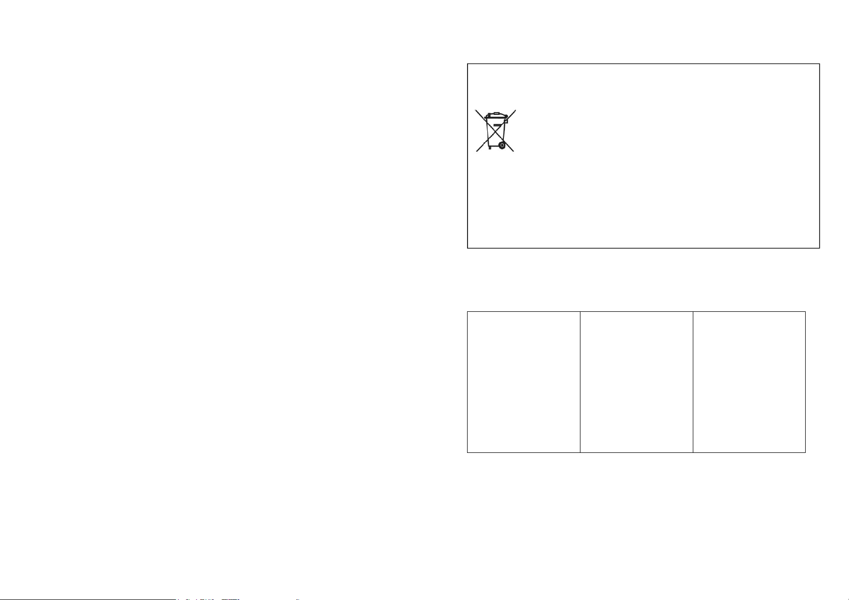
Directive 2002/95/EC, 2002/96/EC and 2003/108/EC on the restriction of the use
of certain hazardous substances in electrical and electronic equipment, and
waste electrical and electronic equipment
This symbol, crossed out wheelie bin, on the product or on its
packaging indicates that this product must not be disposed of with
your other household waste.
Separate waste collection of this appliance is organised and managed by the
manufacturer. It is the user’s responsibility to contact the manufacturer and follow the
waste treatment system the manufacturer has adopted for separate waste collection.
The separate collection and recycling of your waste equipment at the time of disposal
will help to conserve natural resources and ensure that it is recycled in a manner that
protects human health and the environment.
7.3 WEEE Waste of Electric and Electronic Equipment

18
6 Using the machine
6.1 - Foreward
ATTENTION!
Only authorized personnel can use the machine.
Before beginning work the operator must make sure that all the protections are in
place and that the safety devices are fitted and working properly. If not, switch off
the machine and contact the head of maintenance.
6.2 - Using the sieve
The extractable sieve “1” in
stainless steel enables
obtaining a uniformly grated
product, avoiding sieving.
It must be requested upon
ordering the machine.
7 Maintenance
7.1 - Foreward
ATTENTION!
Every maintenance and cleaning operation on the grater must only be done with
the machine at a standstill, disconnected from the power supply.
The area where maintenance operations are carried out must always be kept clean
and dry. Do not allow unauthorized personnel to work on the machine.
Any replacement of parts must be made with original spare parts at authorized
work shops or directly by the manufacturer.
ATTENTION!
Disconnect the machine from the electrical supply before cleaning it.
Do not clean the machine with jets of water.
Only use non-toxic detergents, designated for cleaning components for use with
food products.
Fig. 6.2.1
3
Index
1. Delivery and warranty 5
1.1 Introduction
1.2 How to keep and use this manual
1.3 Warranty
1.4 Description of the machine
1.5 Use
1.6 Prohibited uses
1.6.1 Lighting
1.7 Identification
1.7.1 Safety and warning plates
1.8 Protections and safety devices
1.9 Working positions
1.10 Vibrations
2. Technical features 10
2.1 Main parts
2.2 Technical features
2.3 Machine dimensions and weight
2.4 Noise level
2.5 Electrical diagrams
2.5.1 230-V single-phase electrical diagram
2.5.2 400-V three-phase electrical diagram
2.5.3 220-V three-phase electrical diagram
3. Testing, transport, delivery, and installation 14
3.1 Testing
3.2 Machine delivery and handling
3.3 Installation
3.3.1 Package disposal
3.3.2 Moving the machine
3.4 Connection to electrical system
3.4.1 Three-phase machine
3.4.2 Single-phase machine
4. Commands 15
4.1 List of commands
5. Start up and stop 16
5.1 Checking the correct electrical connection
5.2 Checking the presence and efficiency of protections
and safeties
5.3 Checking the efficiency of the stop button
5.4 Start up
5.5 Stop

4
6. Using the machine 18
6.1 Foreward
6.2 Using the sieve
7. Maintenance 18
7.1 Foreward
7.2 WEEE Waste of Electric and Electronic Equipment
8. Problems and solutions 19
8.1 Problems, causes and solutions
17
1. Microswitch on the lever
While the machine is running lift the presser until the microswitch ntervenes
and stops the machine.
Keep the presser still in the point in which the microswitch interve nes and
check that the space between the loading inlet and the presser is such to block
fingers from entering.
If this is not the case contact an authorized reseller or the manufac turer.
2. Microswitch on the container
While the machine is running extract the plexiglass container and make sure
that the machine stops.
5.3 - Checking the efficiency of the stop pushbutton (fig. 4.1.1)
While the machine is connected to the power supply and the utensil is moving
press the pushbutton “2” fig. 4.1.1
5.4 - Start up
- Set the differential switch fitted upstream at "I". The light indicator “3” fig.4.1.1
will light up, indicating that the machine is powered
- Press the start pushbutton “2” (fig. 4.1.1) to start the machine.
Note
If the presser is in an “open” position the machine will not run, therefore it will have
to be lowered.
5.5 - Stop
- Press the stop pushbutton "1" fig 4.1.1 to stop the running of the machine; the
light indicator “3” fig. 4.1.1 will remain on to indicate that the machine is powe-
red.
- Then set the differential switch installed upstream at "0", in this way disconnec-
ting the machine.
Note
Each time a work shift finishes or the machine is left to rest, the differential switch
must be left set at “0”.

16
5 Start up and stop
5.1 - Checking the correct electrical connection
ATTENTION!
Check that the feeding line corresponds to the value reported on the identification
plate of the machine and that it is outfitted with an efficient floor plug.
1. Put the plug into the electrical outlet.
2. Set the differential switch in position "I". The lit indicator “3” fig. 4.1.1, indicating
that the machine is powered, must be illuminated.
3. Press the pushbutton “2” fig. 4.1.1 to start and immediately afterwards press
the stop one “1” fig. 4.1.1, checking the rotation direction of the roller.
Note
The presser must be in a low position.
The roller rotation direction must be the same
as the one indicated by the arrow fig. 5.1.1
5.2 - Checking the presence and efficiency of protections and
safeties
Fig. 5.1.1
2
1
Fig. 5.2.1
5
1 Delivery and warranty
1.1 - Introduction
ATTENTION!
The purpose of the symbols used in this manual is to draw the reader’s attention to
points and operations that can endanger the personal safety of the operators or
risk damaging the machine.
Do not use the machine unless you are certain that you have correctly understood
these warnings.
ATTENTION!
For greater clarity some illustrations in this manual show the machine or parts of it
with the panels or carters removed.
Do not use the machine in such conditions; all protections must be correctly fitted
and in perfect working order.
This manual cannot be reproduced, even partially, and its contents cannot be used
for purposes other than those permitted by the manufacturer.
Any violations of the above will lead to punishment according to law.
1.2 - How to keep and use this manual
The purpose of this manual is to instruct the user, through texts and figures, on
transport, handling, use, and maintenance of the machine; the manual must there-
fore be carefully read before using the machine. Carefully keep this manual near
the machine in an easily and quickly accessible place for future reference.
If the manual is misplaced or damaged, ask your dealer or manufacturer for a
copy.
If the machine is sold, inform the manufacturer of the name and address of the
new owner.
The manual reflects the state of technology at the moment the machine is sold and
cannot be considered inadequate if it is subsequently updated due to newly gained
knowledge.
In this regard the manufacturer reserves the right to update its products and ma-
nuals without being obliged to update previous products or manuals apart from
exceptional cases.
If in doublt consult the nearest servicing center or the manufacturer.
The manufacturer aims to continuously optimize its product.
For this reason any comments or suggestions on how to improve the product and/
or manual are welcome.
The machine has been delivered to the user under the warranty conditions in force
at the time of purchase.
Contact your supplier for any clarifications needed.

6
1.3 - Warranty
The user is not authorized to tamper with the machine for any reason. If there is a
fault contact the manufacturer. Any attempts at dismantling or tampering with any
component of the machine in general by the user or unauthorized personnel will
cause the lapse of the declaration of conformity according to the EEC Directive
2006/42, will render the warranty null and void and the manufacturer will be
exempt from any responsibility for damage to people or things due to such tampe-
ring.
The manufacturer is also exempt from all responsibility in the following cases:
- Incorrect installation;
- Improper use of the machine by inadequately trained personnel;
- Failure to comply with the regulations in force in the country in which the ma-
chine is used;
- Lack of or insufficient maintenance;
- Use of unoriginal spare parts or spare parts not specifically designed for the
model;
- Total or partial failure to follow the instructions.
1.4 - Description of the machine
The grater you have purchased is a simple, compact and powerful machine, with a
high yield.
- Since it must be used to grate food products the components that can come into
contact with the product have been carefully chosen to guarantee maximum hygie-
ne.
- The base is made of micro shot-peened stainless steel.
- The inlets have been treated with a buffering procedure to facilitate clea ning.
- The roller is made of stainless steel to guarantee maximum hygiene and make it
last longer.
- The motor is self-ventilated to keep yield constant during the prolonged use of the
machine.
- The stainless steel extractable sieve (provided upon request) is used to grate the
bread uniformly.
The models represented in this manual have been manufactured in compliance
with the EEC Directive 2006/42 and modifications thereafter.
In case of an accident the manufacturer cannot be held responsibile if the machine
has been modified or tampered with, if the safety protections have been removed,
or if the machine has been used for purposes prohibited by the manufacturer.
1.5 - Use
The machine has been designed and built to grate cheese, bread or similar pro-
ducts.
It must be used in professional environments and by skilled personnel who are
trained to operate in the sector and have read this manual.
Use the grater only when it is securely placed on a solid work table. The dimen-
sions of the product must enable it to fit in the loading inlet.
15
3.4 - Connection to the electrical system
ATTENTION!
Make sure the electrical source corresponds to the value reported on the identifica-
tion plate of the machine. Each operation should be carried out only by specialized
personnel authorized by the appropriate supervisor. Connect the machine to a
network with an efficient floor plug.
3.4.1 - Three-phase machines at 400 Volt-50 Hz and three-phase machines
at 230 Volt - 50 Hz
In these set ups the machine is outfitted with a
feeding cable with a section of 4 x 1.5 and a length
of about 1.5 meters. Connect the cable to the thre-
e-phase electrical supply network, inserting a 16-
Amp magnetothermic differential switch.
3.4.2 - Single-phase machine at 230 Volt-50 Hz
In this set up the machine is outfitted with a feeding
cable with a section of 3 x 1.5 and a length of
about 1.5 meters.
Connect the cable to the 230 V—50 Hz single-phase electrical supply network,
inserting a 16-Amp magnetothermic differential switch.
For machines with voltages different from those mentioned consult the manufactu-
rer.
If the feeding cable needs to be extended, use a cable with the same section as
the one supplied by the manufacturer.
4 Commands
4.1 - List of commands
1 - Stop pushbutton
- Stop pushbutton: black color
- Press to stop the machine
- The led on the pushbutton lights up only
when the stop pushbutton is pressed
(4 fig. 4.1.1)
2 - Start pushbutton
- Start pushbutton: gray color
- Press to start the machine
3 - Lit indicator of connection to the mains
- White color
- It indicates the connection of the machine to the network.
N.B.: usually it is BLUE or it is indicated by N° 4
Fig. 4.4.1

14
3 Testing, transport, delivery, and installation
3.1 - Testing
The machine in your possession has been tested in our facotry to ensure it runs
properly and is correctly regulated.
3.2 - Machine delivery and handling
All the forwarded material has
been accurately checked prior to
delivery to the shipping agent.
Unless otherwise stipulated by
the client or hindered by
particularly burdensome
transport, the machine is
wrapped with nylon and
carboard.
The packaging dimensions are
shown in fig. 3.2.1 When the machine is received
check that the packaging is intact. Should the packaging be damaged sign the
transport documents, noting that: " I accept, but ..." and the reason.
Once the package has been opened, if machine components are found to have
been genuinely damaged, declare such damage to the shipping agent within three
days of the date indicated on the transport documents.
3.3 - Installation
ATTENTION!
The area where you intend to install the machine must be flat and solid.
Furthermore, the machine must be positioned with ample space around it.
This enables greater maneuverability during working phases and guarantees
access for periodic maintenance. Ensure sufficient lighting around the machine to
guarantee correct visibility for the machine operator.
3.3.1 - Package disposal
The components of the packaging such as cardboard, nylon and wood can be
freely disposed of as they are compatible with solid urban waste.
Nylon is a pollutant if it is burned because it produces toxic fumes. Do not burn and
do not throw away but dispose of it according to the laws in force.
If the machine is delivered in countries in which there are particular laws, dispose
of the packaging according to the presciptions of these laws in force.
3.3.2 - Moving the machine
ATTENTION!
Lift the machine with a forklift of suitable capacity.
Check the stability and positioning of the weight on the forks,
especially along uneven, slippery or inclined paths. When mo-
ving the machine keep the load as low as possible to guaran-
tee greater stability and visibility.
Stabilize the grip by widening the forks of the forklift.
Gross weight (Kg)
HP 1,5 HP 2
30 39
Overall dimensions (mm)
HP 1,5 HP 2
A 660 800
B 470 600
C 610 520
B A
C
Fig. 3.2.1
Fig. 3.3.1
7
1.6 - Forbidden uses
The machine must only be used for the purposes expressly intended by the manu-
facturer. In particular:
- Do not use the machine to grate food products other than cheese, bread and
the like.
- Do not use the machine if it has not been correctly installed with all the protec-
tions intact and correctly assembled to avoid the risk of severe injury.
- Do not access electrical components without having previously disconnected
the machine: risk of electrocution.
- Do not work products that are bigger than what can be totally contained in the
feeding inlet.
- Do not wear clothes that do not comply with safety regulations. Consult your
employer for safety regulations and the safety devices required.
- Do not use the machine if it is not working correctly.
Before starting the machine make sure that any dangerous condition has been
appropriately eliminated. If a fault occurs, stop the machine and notify persons
in charge of maintenance.
- Do not allow unauthorized personnel to carry out work on the machine.
In the event of emergency treatment due to an accident caused by electrical
shock, first remove the victim from the conductor (as he will be unconscious).
This operation is dangerous as the victim is a conductor in this case and tou-
ching him could cause electrocution.
Therefore disconnect the contact directly from the power supply valve or, if this
is not possible, distance the victim using insulating material (wooden or pvc
sticks, fabric, leather, etc.).
A doctor should be promptly called and the patient should be taken to the ho-
spital.
1.6.1 - Lighting
Sufficient natural and artificial lighting must be provided around the machine. Li-
ghting must be disposed of in compliance with the laws in force of the country the
machine is installed in.
In any case, lighting must be uniform and guarantee operator visibility in every
point of the machine and it must not create dangerous reflections.
The lighting must enable a clear reading of the control panels and the individuation
of emergency pushbuttons.
1.7 - Identification
An exact description of the "Model", the "Serial number" and the '"Year of Con-
struction" of the machine will enable our servicing department to provide rapid,
efficient responses. Always indicate the above information whenever you contact
the servicing department.
Use the data on the plate shown in fig. 1.7.1.
8
As a memorandum we suggest filling in your machine data in the following box.
ATTENTION!
Do not, for any reason, alter
the data given on the plate.
1.7.1 - Safety and warning plates (fig. 1.7.2)
ATTENTION!
Do not intervene on electrical parts while the machine is connected to the power
supply.
Risk of electrocution.
Observe the warnings on the plates. Failure to observe them can cause se-
rious injury.
Make sure the plates are always fitted and readable. If not, fit or replace them.
Grater model…....…………
Serial N°………………….
Year of construction…………….
Type……………………………...
A = Grater model
B = Serial number
C = Motor power Watts
D = Amperes
E = Motor frequency Volts
F = Machine weight in Kg
G = Manufacturer
VOLT 230 VOLT 400
C
A
B
Fig. 1.7.1
A
B
C Fig. 1.7.2
13
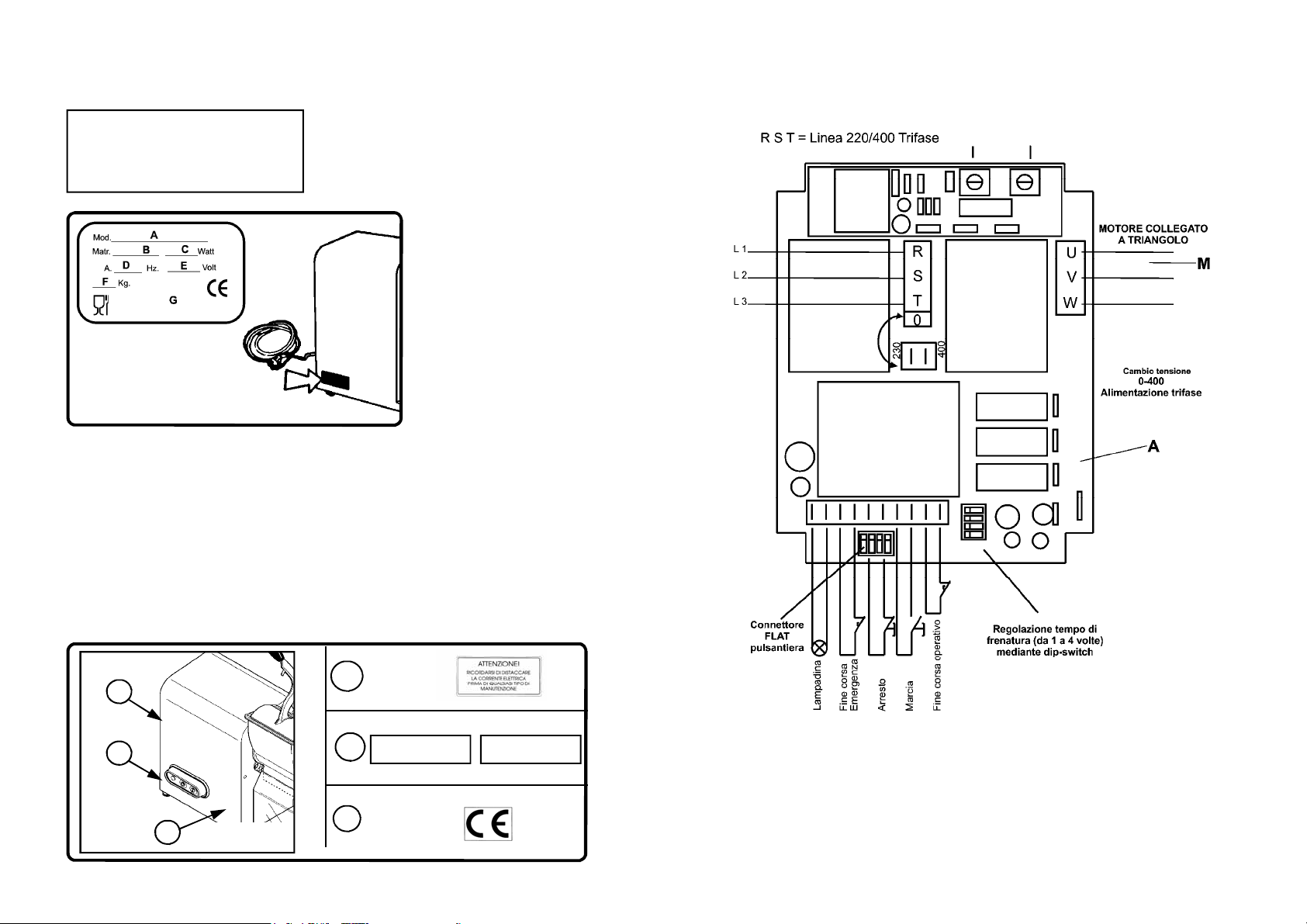
2.5.3 - 220 three-phase electrical diagram
KEY
A= motor command card
M= motor
L1, L2, L3 = three-phase line
Fig. 2.5.3

12
2.5.2 - 400-V three-phase electrical diagram
KEY
A= motor command card
M= motor
L1, L2, L3 = three-phase line
Fig. 2.5.2
9
1.8 - Protections and safety devices
ATTENTION!
Before using the machine make sure that the devices are correctly positioned and
in perfect working order.
At the beginning of each work shift check that they are fitted and working properly;
if not, notify the head of maintenance.
1. Microswitch on the lever
The machine is outfitted with a microswitch on the lever of the inlet. This works
by blocking the machine when the lever remains lifted or the inlet is completely
disassembled.
2. Microswitch on the container
The machine is outfitted with a microswitch on the plexiglass container. When
the container is extracted the machine stops fig..1.8.1.
ATTENTION!
Do not tamper with the safety devices in any way.
1.9 - Working positions
The correct working position for the operator to
optimize the running of the grater is indicated in
fig. 1.9.1.
2
1
Fig. 1.8.1
Fig. 1.9.1
10
1.10 - Vibrations
The vibrations that the machine transmits to the table are not important.
2 Technical features
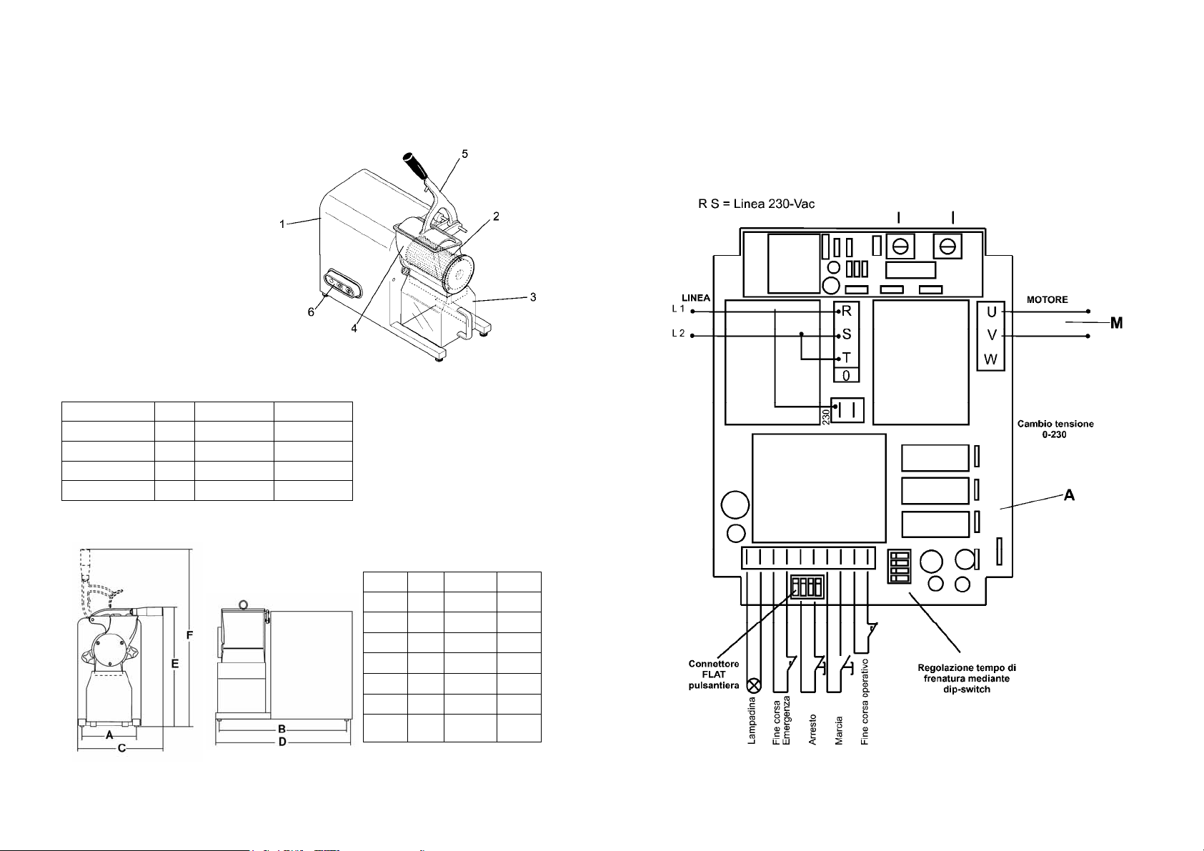
2.1 - Main parts
To facilitate the understanding of
the manual the main machine com-
ponents are listed below and shown
in fig. 2.1.1.
1. Machine body
2. Grater roller
3. Plexiglass container
4. Grater inlet
5. Inlet lever
6. Pushbutton panel
2.2 - Technical features
2.3 - Machine dimensions and weight
Fig. 2.1.1
MODELLO HP 1,5 HP 2
Motor Hp 1,5 2
Feed V 230-400V/50Hz 230-400V/50Hz
Roller revs R.P.M. 1.400 1.400
Inlet dimensions mm 140 x 80 190 x 95
HP 1,5 HP 2
A 185 210
B 395 470
C 260 360
mm
mm
mm
D mm 460 560
E mm 420 490
F mm 590 720
Net
weight kg 27 34,5
Fig. 2.3.1
11
2.4 - Noise level
Testing of the level of noise emitted from the machine indicates that the level is
lower than 70 dBA.
The manufacturer can supply a copy of the noise test upon request.
2.5 - Electrical diagrams
2.5.1 - 230 V - 50 Hz single-phase electrical diagram
KEY
A= motor command card
M= motor
L1, L2 = single-phase line
Fig. 2.5.1
This manual suits for next models
1
Table of contents
Other CHEFOOK Kitchen Appliance manuals


