Ashcroft ATE-2 User manual

I
I&M002-10233
ASHCROFT ATE-2
Operation and
Maintenance Manual
0.054
PSI
0.86
inH20

II

1
TABLE OF CONTENTS SECTION TOPIC PAGE
Section 1. Warnings ...................................................................................................................3
Section 2. Introduction..................................................................................................................7
Section 3. Specifications...............................................................................................................8
Section 4. Base Unit Overview ...................................................................................................10
Section 5. How To Obtain Programming Pass Codes.................................................................11
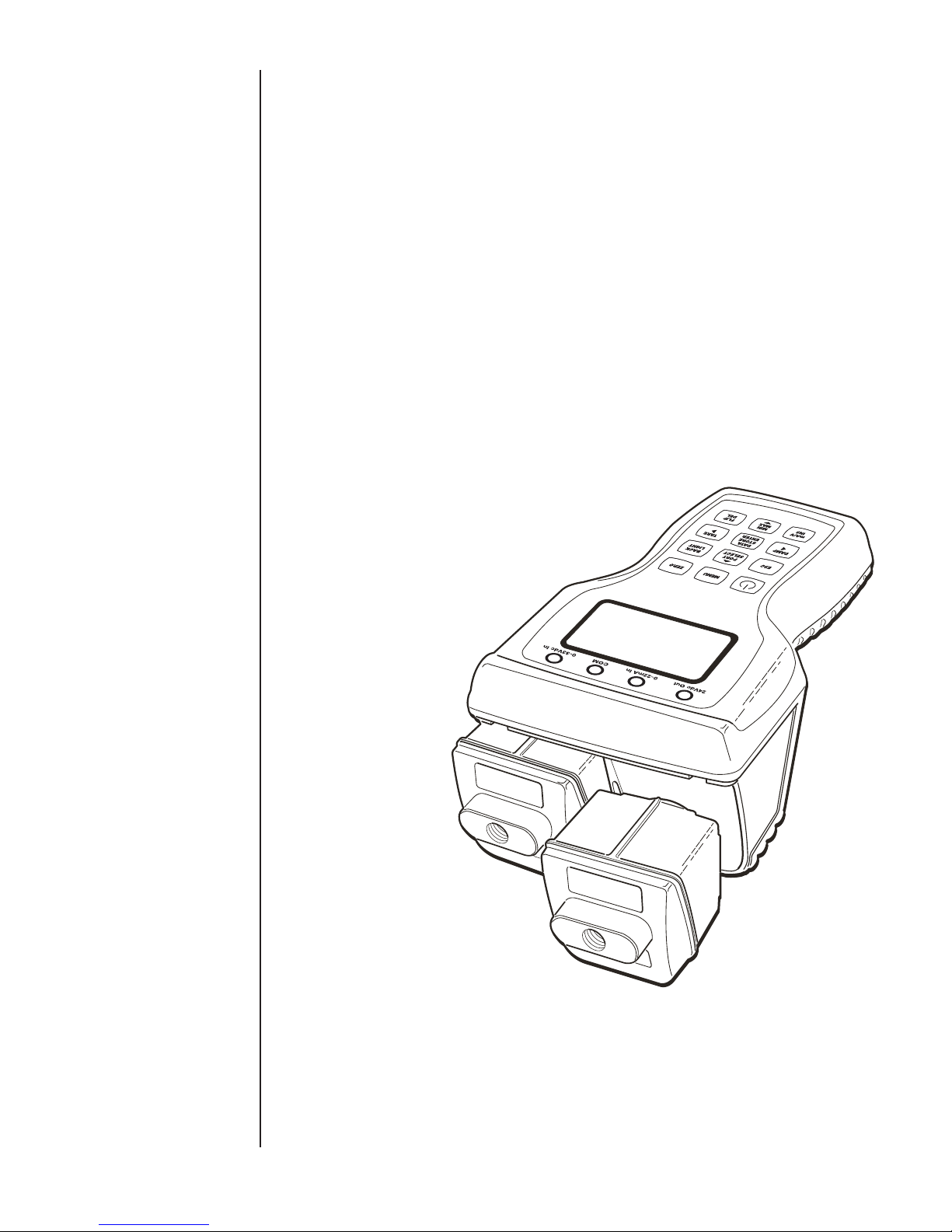
Section 6. Module Overview .......................................................................................................11
Section 7. Unpacking .................................................................................................................14
Section 8. Storage .................................................................................................................14
Section 9. Cleaning .................................................................................................................14
Section 10. Battery Installation .....................................................................................................14
Section 11. Module Installation.....................................................................................................15
Section 12. Startup Basic Function ..............................................................................................15
Section 13. Key Function Overview ..............................................................................................17
Section 14. Measurement Mode Functions
a. ESC .................................................................................................................18
b. Port Select ...........................................................................................................18
c. Data Storage........................................................................................................18
d. Zero .................................................................................................................18
e. Back Light ............................................................................................................18
f. Damping .............................................................................................................19
g. Manual Datalogging.............................................................................................19
h. Tare .................................................................................................................20
i. mA/V Monitoring ..................................................................................................22
j. Wiring Diagrams ..................................................................................................22
k. 24VDC Power Supply Enable/Disable .................................................................23
l. Min/Max Function ................................................................................................24
Section 15. MENU Mode Functions and Programming ................................................................25
a. MENU Mode General Key Functions...................................................................25
b. Base Unit Set Up .................................................................................................26
i. Programming Date and Time.........................................................................26
ii. Programming Owner Name ...........................................................................27
iii. Program Auto Off and Back Light Timers ......................................................27
c. Engineering Units Selections...............................................................................28
d. H2O Temperature Conversion Selection..............................................................29
e. Programing User Defined Unit of Measure..........................................................29
f. Datalogging Setup ...............................................................................................30
i. Set Channel Tag Names ................................................................................31
ii. Program Auto Datalog Time...........................................................................31
iii. Initiate Auto Datalogging................................................................................32
iv. Initiate Manual Datalog ..................................................................................32
v. Review Datalog Data .....................................................................................33
vi Export Data to SD Card.................................................................................35
vii. Clear Internal Memory Storage .....................................................................35
Congratulations on your purchase of a Ashcroft ATE-2, one of
the finest precision pressure measuring instruments available
anywhere. These instruments are precision devices, designed to
measure, indicate pressure, temperature, DC voltage or current
with an extremely high degree of accuracy and are rugged
enough to provide laboratory performance in field service. All
parts have been designed and selected for such service and with
proper care and maintenance this instrument will perform within
specifications for years of trouble free service.

2
g. Switch Test...........................................................................................................35
h. Percent (%) Error Function ..................................................................................37
i. Dual Mode Functions...........................................................................................41
j. RTD Temperature Measurement..........................................................................42
k. Thermocouple Temperature Measurement..........................................................45
l. Firmware Update .................................................................................................47
m. Communications Interface ...................................................................................55
i. USB Cable Installation...................................................................................55
ii. Driver Installation ...........................................................................................56
iii. Terminal Set Up .............................................................................................58
iv. Inquiry Mode..................................................................................................59
v. Journal Mode .................................................................................................60
vi. ISO 1745 Mode..............................................................................................60
n. Calibrate Base Unit..............................................................................................60
o. Pressure Module Calibration ...............................................................................66
Section 16. Appendices
A. Conversion Factor Table ................................................................................71
B. Trouble Shooting and Error Codes ................................................................72
C. ISO Commands .............................................................................................77
D. RTD Probe Connections, TC External Reference Connection ......................79
E. System Accuracy With Thermocouple Interface ............................................80
F. Approved SD Data Cards ..............................................................................80
TABLE OF CONTENTS (cont.)

3
ASHCROFT ATE-2 GENERAL INFORMATION The information in this manual pertains to Ashcroft ATE-2 Hand
Held Calibrators; referred to as the HHC or ATE-2. This manual
also covers sensing modules used with the HHC; referred to as
AM2 modules.
This manual provides the following information:
• Precautions, Warnings and Safety Instructions
• Product Specifications
• Basic Maintenance
• Verification and Test Procedures
• Programming Instructions
• Calibration and Adjustment Procedures
• Accessories and Replaceable Parts
The ATE-2 is intended to perform the following functions
• Display one or two high accuracy pressure and/or tempera-
ture measurements
• Display one DC voltage or current value
• Record datalogs of the displayed measurements (up to
16,000 records on internal memory organized in up to 64
datalogs)
• Transfer datalogs to an onboard SD memory card
• Communicate directly to a PC via USB connection
• Allow for accurate measurement of various pressure and
temperature ranges by use of interchangeable Quick-Select
modules
• Allow for field recalibration of base unit and pressure
modules.
• Provide power to devices from an internal 24Vdc loop supply
(non-I.S. only)
Terms used in this manual
• HHC or Base Unit refers to the Model ATE-2 Hand held Cali-
brator Base Unit
• Capacitive Module refers to Model AM2-1 low pressure
sensor module
• Piezo Module or Piezoresistive Module refers to Model
AM2-2 high pressure sensor module ( Note the 10K psi
range, only, uses a Polysilicon thin film sensor)
• Quick-Select Module refers to any pressure or temperature
module model noted above
All Ashcroft Products and Parts carry a warranty against defec-
tive material or workmanship for a period of one (1) year from the
date of shipment. (See complete policy, page 81.)
Information provided in this document is for the use of qualified
personnel only. Do not perform tests or calibrations described in
this manual unless you are qualified to do so.
Use the ATE-2 calibrator only as described in the user manual,
supplements and appendices.
TERMS IN THIS MANUAL
SECTION 1.0 WARNINGS
WARRANTY INFORMATION
WHEN YOU SEE THESE SYMBOLS IMPORTANT APPLICATION INFORMATION
IMPORTANT SAFETY INFORMATION

4
IMPORTANT
Please read the entire manual thoroughly before using the instru-
ment or attempting any service or repair work. The instructions in
this manual are intended to be performed by qualified instrumen-
tation or technical personnel only. This manual should be kept
with the instrument or in a place of safe keeping at all times, as
it contains pertinent information for operation and maintenance.
Additional manuals can be ordered through Customer Service. If
additional assistance is needed, contact our Customer Service
Staff at:
Willy Instrumentos de Medição e Controle Ltda.
(An Ashcroft® Inc. Company)
Rua João Pessoa, 620 - São Caetano do Sul -
São Paulo - Brazil - 09520-000
Tel.: (55 11) 4224-7400 • Fax: (55 11) 4224-7477
[email protected] • www.ashcroft.com.br
Please be sure to include instrument model number and serial
number in all correspondence to assure proper identification.
Ashcroft Inc. does not recommend trouble-shooting or repairs
beyond the scope of this manual. Problems which cannot be
remedied by following the instructions in this manual should be
referred to the manufacturer. Immediate assistance can often be
supplied by telephone. Defective components will be repaired or
replaced by the manufacturer at his discretion. Repaired products
will be returned to the user by the same mode of shipment. Air-
mail and air express is recommended for urgent shipments.
Electronic pressure instruments must be selected in accordance
with industry codes and safety practices to avoid the possibility of
misuse or misapplication which could result in personal injury or
property damage. Personnel responsible for selection and instal-
lation should also be familiar with the safety recommendations of
ASME B40.1, that apply to elastic pressure elements and their
application in general and specific services. ANSI B40.1 is avail-
able from:
ASME
345 East 47th Street
New York, NY 10017
Pressure – Select a range so that the maximum applied pres-
sure will never exceed the upper range limit.
Vibration – Excessive vibration could cause loosening of
components resulting in loss of instrument accuracy
or failure to provide valid data.
Pulsation – Excessive pressure pulsation could result in fatigue
failure of the pressure element.
Temperature – Operation of the instrument in an environment
where temperatures are in excess of design ratings
may result in loss of accuracy and failure.
Process – Pressure boundary materials must be resistant to
the process media. Failure to assure compatibility
may result in pressure sensing element deterioration
or failure. Instruments used on high pressure gas,
or potentially hazardous service, such as oxygen
should be carefully selected in accordance with the
recommendations of ANSI B40.1.
Hazardous Location – Only approved explosion proof or intrin-
sically safe instruments should be used in hazard-
ous locations.
Electro-Magnetic Interference – Instruments should not be used
in locations where EMI/RFI conditions exceed
design ratings, to avoid erroneous performance.
PURPOSE AND SCOPE
OF MANUAL
SAFETY PRECAUTIONS:

5
Warning to avoid shock or personal injury
• Follow all applicable equipment safety procedures.
• Inspect the calibrator before use. Do not use the calibrator if
it appears damaged.
• Close battery door and secure with lock screw before using
the calibrator.
• Check all test leads for continuity, damaged insulation or
exposed metal. Replace any damaged leads.
• Use the proper terminals, mode and range for any measur-
ing and sourcing application.
• Connect the common lead before connecting the live test
leads.
• To prevent damage to the unit under test, be sure that the
calibrator is in the correct mode before connecting leads.
• Never apply more than 33 volts between input terminals or
between any terminal and ground.
• When using probes keep fingers away from probe contacts.
• Do not allow water or other liquids inside the calibrator case.
• Do not operate the calibrator near explosive gas or vapor
unless the calibrator is marked as approved for hazardous
area service.
• Never open the ATE-2. There are no field serviceable
components. This will void the warranty.
• When measuring pressure, be sure that the process pres-
sure line is shut off and depressurized before connecting or
disconnecting a pressure module.
• Always use proper tools to avoid damage to pressure
measurement modules. Use a wrench to hold the module
manifold, and a second tool to tighten the mating fitting. See
drawing figure in section 12.
• Replace batteries only with approved AA alkaline batteries
(Quantity 4). Never mix new and used batteries in the cali-
brator.
Warnings for Intrinsically Safe approved versions only
(Refer to Supplement I.S. Manual I&M002-10212)
• When marked as approved the ATE-2 calibrator is agency
approved for use in areas when potentially flammable or
explosive gas or vapor may occur. These areas are referred
to as hazardous (classified) locations in the United States,
as hazardous locations in Canada, as potentially explosive
atmospheres in Europe and as explosive gas atmospheres
in other parts of the world. The HHC’s voltage and current
input jacks have entity parameters and as such can be uti-
lized in a hazardous location to connect to other apparatus
as long as said apparatus meets the requirements of the
entity parameters.
• When marked with the following Symbols the calibrator is
approved by Factory Mutual (FM) for use in Class 1 Division
1, Groups A,B, C,D hazardous areas, by ATEX for use in Ex
ia ll C T4 Ga -20C<Ta<+50C and by CSA for use in Class 1,
Division 1, Groups A, B, C, D
ADDITIONAL WARNINGS
WARNINGS CONT.

6
• Before entering a hazardous area, close both the battery
door and USB/SD card door, and secure both with lock
screws.
• The battery access cover is not to be removed while in a
hazardous area.
• The USB/SD access door is not to be removed while in a
hazardous area.
• Replace batteries only in a non-hazardous area.
• Use only Duracell Model MN1500 AA alkaline primary cell
batteries.
• The USB connection-data transmission and power input- are
restricted to be used in a non-hazardous area only.
• The non-hazardous area USB apparatus –computer port,
wall supply, etc., connected to the USB port of the HHC,
must be assessed and conform to section 6.2.5 of EN60079-
11. This precaution is to protect the integrity of the safety
components within the HHC, which insures its intrinsic safety
rating while in the hazardous location.
• When using non- assessed USB equipment, accessory
part number 101C225-01, USB protection device, is to be
inserted between the HHC USB port and the non-assessed
apparatus.
• Do not power the calibrator by USB cable in a hazardous
area; this action will invalidate the calibrator’s intrinsic safety.
• Intrinsically safe installation diagrams, entity parameters and
warnings are included in drawing 825A028 included in the
supplemental I.S. manual.
ADDITIONAL WARNINGS CONT.
250 EAST MAIN ST.
STRATFORD, CT 06614
www.ashcroft.com
INTRINSICALLY SAFE/SÈCURITÈ INTRINSÈQUE Exia
CL I, DIV 1, GR A, B, C, D. T4 -20°C≤Ta≤+50°C
II 1 G FM12ATEX0035X
Ex ia II C T4 Ga -20°C≤Ta≤+50°C
ENTITY PARAMETERS
Ui=33Vdc Ii=300mA Ci=0 Li=0 Pi=1.5W
Uo=5.735Vdc Io=586A Co=46f L0=1H Po=840W
See Dwg #825A028 for installation, batteries
and warnings
HAND HELD CALIBRATOR 6D49 E171189
Unit contains a lithium battery. Panasonic #BR1225
is the approved replacement battery. Use of another
battery may present a risk of fire or explosion. See
owners manual for safety instructions.
WARNING:
0518
Label Part# 238A746-01Rev D

7
0.054
PSI
0.86
inH20
The ATE-2 is a simple, yet sophisticated, high accuracy, battery
or USB powered, handheld calibrator device. Used together with
interchangeable pressure and temperature modules, this device
measures, displays and can record pressure, temperature, DC
voltage or milliamp current. Up to three measurements can be
simultaneously displayed.
A standard system consists of a base unit and one or two
Quick-Select modules.
Quick-Select pressure modules are available in over 50 standard
pressure ranges in gauge, absolute, vacuum and compound
ranges capable of measuring pressures from 0.25 inches water
column up to 10,000 pounds per square inch.
Quick-Select temperature modules are designed to work with
several common RTD types including Pt1000, Pt100, Ni120,
Cu10, and up to six programmable resistance curves. Thermo-
couple temperature modules work with Types J, K, T, E, R, S, B
and N thermocouples.
SECTION 2.0 INTRODUCTION

8
Optional Agency Approvals
(with modules)
FM Intrinsically Safe Class 1, Division 1, Groups A,B,C,D.
FM Project #3043711
CSA Intrinsically Safe Class 1, Division 1, Groups A,B,C,D,
CSA Report #150912-2653569
ATEX Ex ia ll C T4 Ga -20C<Ta<+50C, File
# FM12ATEX0035X
BASE UNIT PERFORMANCE SPECIFICATION
Update Rate 100 milliseconds per parameter measured. 300 milliseconds max
when 2 modules and current/ voltage monitoring is active
Resolution ± 0.001% of span, 99,999 counts (max, for 110% of pressure
range)
Interface Serial USB, 2.0 ISO 1745
Electrical Measurements
Accuracy (% Span)
0-20 mA, or 0-30VDC (with auto-ranging)
0/10VDC ±0.025
10/30VDC ±0.1
0/20mA ±0.03
Temp. Effect (%Span / F) ±0.001
Temperature Measurements RTD or Thermocouple
On-Board Power Source 24VDC, for use with 4-20mA & voltage output transducers 35ma
maximum
Compatible w/ Custom Firmware Modbus (Optional), Medical Instrument Base (Optional)
Flash Firm Ware upgrade through USB Port possible. (Approximate update time 15 minutes)
SECTION 3.0 PRODUCT SPECIFICATIONS
BASE UNIT PHYSICAL SPECIFICATION
Dimensions 8.7” L X 5.1” W X 3.8” H
Weight 2.4 pounds (includes two modules installed)
Case Material High Impact PC-ABS with rubberized sections
Sensor Module Capacity 2, hot swappable, modules are fully recognized automatically
Display 1.5” X 2.5” Graphic LCD Display with backlight
Power Source/Requirements 4 x AA Batteries (6.4VDC maximum) Duracell Alkaline MN1500,
or via USB port from PC or wall supply (5.25 VDC
maximum, 0.375 Amps maximum)
Real Time Clock Battery Panasonic BR1225, Lithium ion (not field replaceable)
Battery Life 50 hours with 1 module, with no back light at 70°F
40 hours with 2 modules, with no back light at 70°F
AC/DC adaptor (USB Port) USB Micro-B Connector
Electrical Connection 4mm “Banana Jack” sockets, quantity 3 or 4
Electrical Output 24 VDC output, 35mA maximum
Current Input 0-22mA
Voltage Input 0-33 VDC
Interface USB 2.0
Removable Data Storage Type SD
BASE UNIT ENVIRONMENTAL SPECIFICATION
Temperature Effect ±.004%Sp / ° F over compensated range
(+20/+120°F (-7/+50°C)
Enclosure
IP Rating (with modules) NEMA 4X / IP65, suitable for Indoor and Outdoor use
Impact / Drop Resistance IEC 60079 - 0
Warm-up time (to full accuracy) Less than 5 min.
Agency Approvals (w/modules) CE EMC Directive, IEC-61326-1: 200
FCC FCC CFR 47, Part 15, section 15.5 and 15.29
UL UL-61010-1, File # E171189

9
Activated Activated
Feature or Function from Key Pad from Menu
On/Off X
Backlight X
Esc X
Menu X
Flip Screen X
Navigation Keys (4) X
Port Select X
Zero X
mA / V X
Damping X
Tare Capability X
Min / Max Tracking X
Data-Logging w/auto start/auto stop X
Field Calibration (Base Unit and
pressure modules) X
Passcode Lock X
Selectable Eng. Units (12 pre-
programmed and 1 user defined) X
Trip Detect / Dead band Function X
% Error Display X
Dual Mode measurement (DP, Sum) X
Loop Power Supply Activation
(Non-Intrinsically Safe Only) X
SD Memory Card Functions X
SECTION 3.0 PRODUCT SPECIFICATIONS CONT.

10
The base unit functions as a host for the Quick-Select pressure
and temperature modules. The base unit includes two bays for
installation of pressure or temperature modules, an LCD graphic
display with back light, a key pad, a USB micro B receptacle for
communication with a PC, an SD memory card slot and banana
jack connections for DC voltage supply and signal monitoring.
The enclosure is rated to IP65 water resistant.
When pressure and or temperature modules are installed and
the base unit is powered on, it will briefly display the brand name,
data regarding installed modules. Then the HHC will go into mea-
surement mode where it will display up to three values as well as
their respective engineering units of measure. The base unit is
pre-programmed with twelve units of pressure measurement, four
units of temperature measurement, DC voltage 0-30 VDC, DC
current 0-20 ma and also allows the user to program a custom
pressure unit of measure. In measurement mode, the display will
show Battery status, USB connection status, one or two vertical
bar graph indicators indicating percentage of full scale pressure
and other user interface and warning messages when applicable.
The calibrator is equipped with internal memory capable of
storing up to 16,000 records. Datalogs can be transferred to an
optional on board SD memory card to clear internal memory and
allow further data collection. Datalogs can be transferred to a PC
from the SD card and are presented in .csv files which can be
opened by Microsoft Excel software.
-
0.12
in H
2
0
0.000
volts
-
0.001
PSi
POWER
MENU KEY
CH1 MODULE-
ENGINEERING UNITS
CH2 MODULE
READING
CH2 MODULE/
BAR GRAPH
CH1 MODULE-
BAR GRAPH
SD CARD
INDICATOR
USB INDICATOR
24VDC
POWER SUPPLY
INDICATOR
UNIT OF PRESSURE
CH1 MODULE
READING
ZERO FUNCTION
BACK LIGHT
TARE/
RIGHT ARROW
FLIP DISPLAY/
DELETE
ESCAPE
DAMPING/
LEFT ARROW
MILLIAMP/VOLT
SELECT INSERT
VOLT/MILLIAMP
INDICATOR
EXTERNAL
VOLT/MILLIAMP
READING
USB/BATTERY
POWER INDICVATOR
MIN/MAX FUNCTION/
DOWN ARROW
PORT SELECT/
UP ARROW
DATA STORE/
ENTER
CHANNEL 1
MODULE
CHANNEL 2
MODULE
SECTION 4 BASE UNIT OVERVIEW

11
The operator can program several parameters in the calibrator
which are further detailed in this manual. Programmable parame-
ters include:
• Date and time
• Owner name
• Auto off time
• Port selection
• Select Voltage (v) or current (mA) monitoring
• Enable/Disable 24VDC power supply
• Zero modules
• Tare
• Damping
• Percent error function
• Engineering units select
• User defined unit of measure
• Dual sensor mode
• Pressure or Temperature switch test mode
• Calibration of base unit
• Module calibration
• Datalogging via USB
• Datalogging to internal memory
• Transfer datalog to SD card
Owner name and base unit calibration functions are password
protected. The passwords may be obtained by contacting the fac-
tory or downloading the “HHC Secure” application from the web
site. “HHC Secure” will generate the HHC’s unique pass codes
based on user input of the base unit serial number. Make a note
of these pass codes
Owner Pass code_______________________________
Calibration pass code _________________________________
Quick-select modules are available for measuring a wide variety
of pressure and temperature ranges. They can be “hot swapped”
within the base unit while it is powered on without causing any
damage to the base unit or the module. “Hot Swap” refers to
installing or removing modules while the base unit is powered
on. The base unit will recognize the module and display the unit
of measure in which the module was originally calibrated and
labeled. Quick-Select pressure modules are available in accura-
cies from ±0.1% to ±0.025% of span.
SECTION 5 HOW TO OBTAIN PROGRAMMING
PASSCODES
SECTION 6 QUICK-SELECT MODULE
OVERVIEW
SECTION 4 BASE UNIT OVERVIEW CONT.
USB PORT SD CARD PORT
USB MICRO B
CONNECTOR

12
Quick-Select modules when installed in the base unit are referred
to as Channel 1 and Channel 2. Channel 1 is always the module
on the left side of the calibrator when it is held upright with mod-
ules at the top of the calibrator and the LCD display facing the
operator. Channel 2 is on the right side when the base unit is
held in the same position.
AM2-1 pressure modules are low pressure measurement devices
based on micro machined silicon variable capacitance sensors.
They are intended for use with clean dry, nonconductive, non-
corrosive gases. They are available in ranges from 0.25 to 200
inches of water column and can be configured to provide differen-
tial, gauge or compound readings.
AM2-2 are high pressure measurement devices. They are sin-
gle-port modules based on sensors capable of measuring gauge,
absolute, compound or vacuum with ranges spanning from
vacuum to 5 psi to 10,000 psi. All wetted parts are 316 stainless
steel (except for 10k psi module which has 17-4ph stainless
steel) and are intended for use with any pressure medium com-
patible with stainless steel.
AM2-RT1 and RT2 modules are RTD temperature measurement
modules compatible with Pt100, Pt1000, Ni120, Cu10, and up to
six user programmable resistance curves. Measurements can be
displayed in degrees Fahrenheit, Celsius, Kelvin, Rankin or ohms.
The setup menu allows the operator to choose configurations
for 2, 3 or 4 wire RTD probes. In addition, the setup menu also
allows selection of 1, 0.1, 0.01 or 0.001 decimals of resolution.
Accuracy specifications are detailed in the data sheet.
SECTION 6 QUICK-SELECT MODULE
OVERVIEW CONT.

13
AM2-TC1 temperature modules read types J, K, T, E, R, S, B
and N thermocouples and display the measurement in units of
degrees Fahrenheit, Celsius, Kelvin, Rankin or millivolts.
System protection modules AM2-XS are used to protect unused
sensor bays in the base unit from moisture or other contamina-
tion ingress as well as EMI/RFI interference.
Calibration Module AM2-CM allows the operator to easily make
contact with internal connection pins necessary to apply the
required voltage levels for recalibration of the HHC base.
SECTION 6 QUICK-SELECT MODULE
OVERVIEW CONT.

14
Prior to removing the HHC from the packaging material, inspect
all cartons for shipping damage. Document any damage evident
in the event that a damage claim must be made against the ship-
per. After inspection, remove the base unit, module(s), manual
and any accessories purchased from the packaging material.
Retain the packaging for use in returning the HHC to the factory
for future calibration or repair.
Store in an area that is maintained in the temperature range
indicated in the storage temperature in the product specification,
-4/+158F (-20/+70C). Storage of product in environments that
will exceed this temperature limit increases the risk of product
damage.
Note: It is recommended that the product not be left in closed
cars or truck cabs as temperature damage can easily occur due
to drastic temperature changes.
Clean with a cloth moistened with a warm water/ mild detergent
mixture.
1. To gain access to the battery compartment, loosen the strap
assembly by detaching the Velcro connection and move the
strap to the side to allow access to the Phillips head screw on
the battery cover door.
2. Open the battery compartment by loosening the Phillips head
screw located in the battery compartment door immediately
above the product label.
3. Using thumb and forefinger gently lift battery door up and
toward the top of the calibrator to remove door.
4. Install four new AA Alkaline batteries. (Only Duracell Alkaline
part number MN1500 for I.S. units.) Observe polarity markings
to install batteries correctly. Never mix old and new batteries.
5. Reinstall battery door. Be sure that the lower latch tab is
engaged beneath the clasp hook to ensure proper watertight
sealing of the battery compartment.
6.Tighten Phillips head screw in top of cover.
7.Replace strap by tightening strap and secure with Velcro.
Note: if unit will be stored for six months or more be sure to
remove batteries before storage to prevent possible battery
leakage.
SIZE “AA” OR EQUIV
OR UM-3X4
SECTION 7 UNPACKING
SECTION 8 STORAGE
SECTION 9 CLEANING
SECTION 10 BATTERY INSTALLATION

15
1.Hold the base unit, in one hand, with the keypad side DOWN.
2. Holding the Quick-Select module to be installed in the other
hand, align the module with the locking tab up, with the module
bay on the base unit.
3. Slide the Quick-Select module into the base unit until the
retaining/release tab catches in the square cutout in the module
bay of the base unit. This will lock the Quick-Select module into
the base unit. Installation is now complete
Note:
If only one module is to be used, install the Quick-Select System
Protection module provided. Follow the same procedure to install
the system protection module as described above.
Removal of Quick-Select modules
1.Hold the base unit, in one hand, with the keypad side DOWN.
2.Press the locking tab DOWN to release the module.
3. Grasp the Quick-Select module to be removed in the other
hand and gently pull to remove the module. There may be sig-
nificant resistance to pulling due to O-ring seals on the module
needed to maintain water tight integrity.
After the desired Quick-Select module(s) have been installed,
power the calibrator on by pressing the green power key.
When powering on, the LCD display will briefly indicate the
calibrator model number, serial number, owner information
and whether it is an intrinsically safe or not intrinsically safe
model. If pressure or temperature modules are installed, serial
SECTION 12 STARTUP BASIC FUNCTION
0.054
PSI
0.86
inH20
SECTION 11 MODULE INSTALLATION

16
number, range and calibration data for each module will be briefly
displayed before booting up in Measurement Mode.
The HHC is now ready for basic pressure or temperature
measurement.
Pressure readings from installed modules will be displayed in the
engineering unit in which the module was originally calibrated.
Connect the pressure port(s) of the Quick-Select pressure mod-
ule(s) to be used to the pressure source to be measured. If a
gauge pressure measurement is to be made using a low differen-
tial pressure Quick-Select pressure module, be sure to connect
the pressure to be measured to the high pressure port on the
Quick-Select pressure module.
Note: When making connections to pressure ports on Quick-
Select modules always use proper tools such as the proper size
wrench, slip joint pliers or locking jaw pliers to hold the stainless
steel manifold and use a second tool such as a properly sized
wrench to tighten the connection. NEVER tighten the fitting by
holding it only in the base unit
For temperature measurement, connect the RTD probe to be
used to the Switchcraft connector on the interface module then
proceed to Section 15j or 15k for instructions on setting up the
calibrator for temperature measurement.
SECTION 12 STARTUP BASIC FUNCTION CONT.
-
0.17
-
0.004
inH
2
0
PSi

17
SECTION 13 KEY FUNCTION OVERVIEW The most common functions are accessible by dedicated keys on
the keypad. More complex and less often used functions and pro-
grammable features are accessible through an easy-to-navigate
MENU system. A number of the keys have different functions
depending in which mode the HHC is operating. These keys have
white and yellow lettering and icons. The white lettering indicates
the primary key function. Yellow is the secondary function. A brief
overview of the keypad keys and functions follows:
Power Key is used to
switch the HHC on and off.
The MENU key is used to
enter and exit the program-
ming MENU
To Zero installed Quick-
Select Pressure modules
Escape Key to go back one
level when in MENU Mode
or to escape any special
display mode. Also aborts
auto datalogging.
To select installed modules
to apply various functions.
In MENU Mode, to incre-
ment a selected parameter
up once per press.
To switch back light on
and off.
To adjust damping level of
installed module(s) in Mea-
surement Mode. In MENU
Mode it is used as a LEFT
ARROW key.
Multi-function key. In
Manual Datalog Mode,
stores one data point of
value presently shown on
the display. When in Auto-
matic Datalog Mode will
begin or end auto logging
at the programmed inter-
val. When in programming
mode, it is used as the
Enter key to save selected
parameters.
Used to activate the tare
function on installed
Quick-Select modules when
in Measurement Mode. In
MENU Mode used as RIGHT
ARROW key.
To activate measurement of
milliamps or DC voltage in
Measurement Mode.
To display Minimum and
Maximum measured values
in Measurement Mode for
selected channels. In MENU
Mode, it is used to increment
a selected parameter DOWN
once per press.
To rotate LCD display 180°
in Measurement Mode. In
Programming Mode to zero
numeric characters or change
alpha characters to a blank
space.

18
SECTION 14 e. BACK LIGHT FUNCTION
SECTION 14 d. ZERO FUNCTION
During any programming operation pressing the ESC key will
cause the HHC to exit any special display mode or, step back one
programming level if in Programming Mode.
PORT SELECT function is used in several programming appli-
cations including zero, min/max, tare and damping. This allows
the user to choose between installed modules to which an action
is to be performed. PORT SELECT is enabled following the ini-
tialization of a desired function such as zero. The selected mod-
ule(s) will be indicated by having a rectangular box surrounding
the measurement indication. Pressing the PORT SELECT key
repeatedly will allow the user to select the Channel 1 , Channel
2 or both channels if applicable. When desired channel (s) are
selected the ENTER key is pressed to finalize the selection.
The default Data Storage mode is manual and is described in
section 14g and 15f. The HHC is capable of storing pressure,
temperature, voltage or current data for any combination of
installed modules, voltage or current inputs that are active, up
to three simultaneous data points. Each data record will include
a time stamp and up to three measurement values. Headers in
the Datalog report label columns with date, user-programmable
module description (default values are Channel 1, Channel 2,
Ext.) and the engineering unit of measure. Up to 16,000 records
can be recorded. Data records are grouped in Datalogs which
can be manually initiated or automatically logged at user defin-
able time intervals between 100 milliseconds and 24 hours.
Utilized to remove zero offset, up to 10% of full scale range, when
zero pressure is applied.
1. Press the ZERO key. PORT SELECT MENU is entered with
the Channel 1 module selected.
2. Use the PORT SELECT key to select Channel 1, Channel 2 or
both Channels.
3. Press ENTER to zero the selected module or modules, or
press ESC to cancel and return to Measurement Mode
A module must be installed in the HHC base unit to be zeroed.
Additionally, it must be a pressure module, and must be within
10% of full scale of its factory programmed zero.
In the event an attempt is made to zero a module that is absent,
or which is not a pressure module a warning will be displayed in
the notice area stating:
“CH(X) not a pressure mod”.
In the event an attempt is made to zero a module that is more
than 10% of full scale from its factory programmed zero, a warn-
ing will be displayed in the notice area stating:
“CH(X) zero out of bounds”
Press the Back Light key to toggle the light on/off. A user pro-
grammable back light auto off timer can be used to preserve
battery life. Press any key to reset the backlight auto off timer.
SECTION 14 a. ESCFUNCTION
SECTION 14 b. PORT SELECT FUNCTION
SECTION 14 c. DATA STORAGE FUNCTION
–
0.12
in H
2
0
-
0.012
PSi
Table of contents
Other Ashcroft Test Equipment manuals
Popular Test Equipment manuals by other brands

IGT
IGT W46 Information Leaflet

MARTINDALE
MARTINDALE RC2000 instruction manual

Phenix Technologies
Phenix Technologies PAD56 Operation and application manual

Honeywell
Honeywell HPBLT Product installation document

Rohde & Schwarz
Rohde & Schwarz RTM3K-COM4 Getting started

Tektronix
Tektronix MDO4104-6 user manual