Chemtrol 255 User manual

MAN255/04B
$ 10.00
INSTRUCTION MANUAL
CHEMTROL®255 PPM/pH Controller (v. 4.0 and up)
CHEMTROL®250 ORP/pH Controller (v. 4.5 and up)
A Division of SANTA BARBARA CONTROL SYSTEMS
5375 Overpass Road, Santa Barbara CA 93111
TECHNICAL SUPPORT
TOLL FREE 800-621-2279
PHONE 805-683-8833
FAX 805-683-1893
EMAIL [email protected]

MAN255/04B
WARRANTY
This CHEMTROL®Electronic Controller Model ________S/N _____________________________________ is warranted by SANTA
BARBARA CONTROL SYSTEMS (SBCS) to be free from defects in manufacturing and workmanship for a period of FIVE (5) YEARS from
the date of purchase for the electronic module and ONE (1) YEAR for all other components. SBCS will repair or replace, at its option, any
defective part during the warranty period. Labor, shipping or incidental expenses are specifically excluded from this warranty. For warranty
coverage, defective parts should be returned immediately to your CHEMTROL
Dealer or to our factory postpaid with a copy of your
purchase receipt and a detailed description of the malfunction.
TABLE OF CONTENTS
TECHNICAL SUPPORT...........................................................1
WARRANTY.............................................................................2
TABLE OF CONTENTS ...........................................................2
INTRODUCTION......................................................................3
FREE CHLORINE ......................................................3
ORP CONTROL (Models 230/250) ............................3
PPM CONTROL (Models 235/255) ............................3
WATER CHEMISTRY ................................................3
INPUTS AND OUTPUTS ...........................................3
INSTALLATION........................................................................4
LOCATION.................................................................4
SENSOR INSTALLATION .........................................4
MAIN LINE INSTALLATION.......................................4
BYPASS LINE INSTALLATION .................................5
SENSOR CELL ..........................................................5
WATER FLOW...........................................................5
ELECTRICAL ...........................................................................6
VOLTAGE ..................................................................6
PPM BATTERY (Models 235/255) .............................6
REMOTE ALARM ......................................................6
FLOW SWITCH .........................................................6
SETUP MENU..........................................................................6
ACID/BASE FEED .....................................................6
SANITIZER/pH INTERLOCK .....................................6
SAFETY FLOW SWITCH...........................................6
TERMINAL BLOCK WIRING....................................................6
CHEMICAL FEEDERS .............................................................7
CHEMICAL FEED PUMPS ........................................7
EROSION FEEDER ...................................................7
OPERATION ............................................................................7
PPM SENSOR CONDITIONING (Models 235/255) ...7
SENSOR CALIBRATION ...........................................7
GAIN FACTOR (Models 235/255)..............................7
CONTROL SETPOINTS............................................ 7
OVERFEED SAFETY TIMERS.................................. 7
OUT-OF-RANGE ALARMS ....................................... 8
FEED MODE .............................................................8
PROPORTIONAL FEED............................................8
CONTROLLER RESET ............................................. 8
STARTUP ................................................................................ 8
DEFAULT PARAMETERS.........................................8
AUTOMATIC CONTROL ........................................... 8
MAINTENANCE ....................................................................... 9
GENERAL MAINTENANCE.......................................9
EFFECT OF CYANURIC ACID..................................9
PPM SENSOR TESTING (Models 235/255).............. 9
PPM BATTERY (Models 235/255)............................. 9
NO PPM SENSOR CLEANING (Models 235/255)..... 9
ORP AND pH SENSOR TESTING ............................9
ORP AND pH SENSOR CLEANING.......................... 9
SENSOR REPLACEMENT........................................ 9
SENSOR STORAGE ................................................. 9
WINTERIZING ........................................................... 9
PORTABLE TESTER............................................................. 10
ORP SENSOR TESTING ........................................ 10
pH SENSOR TESTING ........................................... 10
ORP AND pH SIMULATION .................................... 10
TROUBLESHOOTING ........................................................... 11
TABLE OF FIGURES............................................................. 11
PARTS LIST .......................................................................... 12
OPTIONS............................................................................... 12
SPECIFICATIONS ................................................................. 12
IMPORTANT SAFETY INSTRUCTIONS
Mandated by ITS Testing Laboratories, Inc
1. READ AND FOLLOW ALL INSTRUCTIONS
2. WARNING - To reduce the risk of injury, do not permit children to use this product unless they are closely supervised
at all times.
3. WARNING - Risk of Electric Shock. Connect only to a grounding type receptacle protected by a ground-fault circuit
interrupter (GFCI). Contact a qualified electrician if you cannot verify that the receptacle is protected by a GFCI. (Only
required for cord-connected units.)
4. Do not bury cord. Locate cord to minimize abuse from lawn mowers, hedge trimmers, and other equipment. (Only
required for cord-connected units.)
5. WARNING - To reduce the risk of electric shock, replace damaged cord immediately. (Only required for cord-
connected units.)
6. WARNING - To reduce the risk of electric shock, do not use extension cord to connect unit to electric supply; provide a
properly located outlet. (Only required for cord-connected units.)
7. SAVE THESE INSTRUCTIONS.

MAN250/04 Page 3
INTRODUCTION
The CHEMTROL®250 Series Controllers are microprocessor-
based digital controllers designed to monitor and control the
sanitizer and pH levels in swimming pools, spas, cooling towers
and industrial applications.
The controllers are available with three types of sensors for
measurement of water acidity (pH) and of sanitizer level in either
PPM (parts per million or milligrams/liter) or ORP in millivolts.
This manual covers new versions (4.0 and up) of five models:
•CHEMTROL®255 PPM/pH Controller,
•CHEMTROL®250 ORP/pH Controller,
•CHEMTROL®240 pH Controller,
•CHEMTROL®235 PPM Controller.
•CHEMTROL®230 ORP Controller.
FREE CHLORINE
As shown on Figure 1, Free Chlorine in water is in equilibrium
under two forms:
•Molecular HOCl, a strong sanitizer and oxidizer,
•Ionized OCl-, a weak sanitizer and oxidizer.
At a pH of 7.5, the two forms are in equal proportions of 50%
each. At lower pH values, HOCl predominates. At higher pH
values, OCl- is dominant.
ORP CONTROL (Models 230/250)
The ORP sensor shows the voltage (in mV) produced by
oxidizers in water.
It responds to strong oxidizers, such as HOCl and its bromine
equivalent HOBr. It also responds to other strong oxidizers that
are used in water treatment, such as Ozone (O3) or Potassium
Monopersulfate (KSO3).
Because HOCl is the primary oxidizer, the signal of the ORP
sensor decreases with increasing pH values.
It is not specific to chlorine or bromine and responds to other
oxidizers.
The chlorine or bromine concentration required to generate a
desired ORP value varies with pH and overall water quality,
particularly Total Dissolved Solids (TDS) concentration, organic
load and cyanuric stabilizer concentration.
The ORP setpoint default value on the controller is 700 mV,
which is recommended to kill germs and bacteria and maintain
good water quality.
PPM CONTROL (Models 235/255)
The PPM sensor is specific to Free Chlorine only.
The controller displays the concentration of Total Free Chlorine
(HOCl + OCl-) in PPM (parts per million or milligrams/liter). It
does not respond to Bromine and/or oxidizers.
The Free Chlorine display does not vary up to a pH of 7.8.
The PPM setpoint default value on the controller is 1.0 ppm,
which is recommended to kill germs and bacteria and maintain
good water quality. It can be adjusted to meet local conditions
and Health Department requirements.
WATER CHEMISTRY
Before starting automatic control, test the water chemistry to
make sure that the pH, Cyanuric Acid and Total Dissolved Solids
are within the ranges recommended by the National Spa and Pool
Institute (NSPI).
The pH should be adjusted manually within 7.4 to 7.6. If it is
below 7.0 or above 8.0, the controller will show an alarm condition
and prevent feeding (programmable option).
To stabilize chlorine against solar UV radiation, a cyanuric acid
level of 20 to 25 ppm is ideal. However, this level can be quickly
exceeded with stabilized chlorine (dichlor or trichlor). Note that
many Health Department codes do not allow stabilizer levels
above 100 ppm. If above 100 ppm, this results in chlorine lock
that shows as low ORP readings even with high chlorine levels.
The Total Dissolved Solid (TDS) level should be below 2,000
ppm. If higher, the water is full of organic and inorganic
impurities and should be dumped and replaced partially or
completely.
For effective pH control, the Total Alkalinity should be between
80 to 120 ppm. If too low, the pH will bounce and be hard to
control. If too high, the pH will be hard to change.
INPUTS AND OUTPUTS
Depending on the model number, the inputs include one or two
sensors:
•a PPM sensor to monitor free chlorine concentration,
•an ORP sensor to monitor ORP or Redox,
•a pH sensor and a safety flow switch (optional).
The outputs are two relays for sanitizer and pH feed - acid or
base - plus a relay for an optional remote alarm or telephone
dialer.
Figure 1 - Equilibrium of Free Chlorine

MAN250/04 Page 4
INSTALLATION
LOCATION
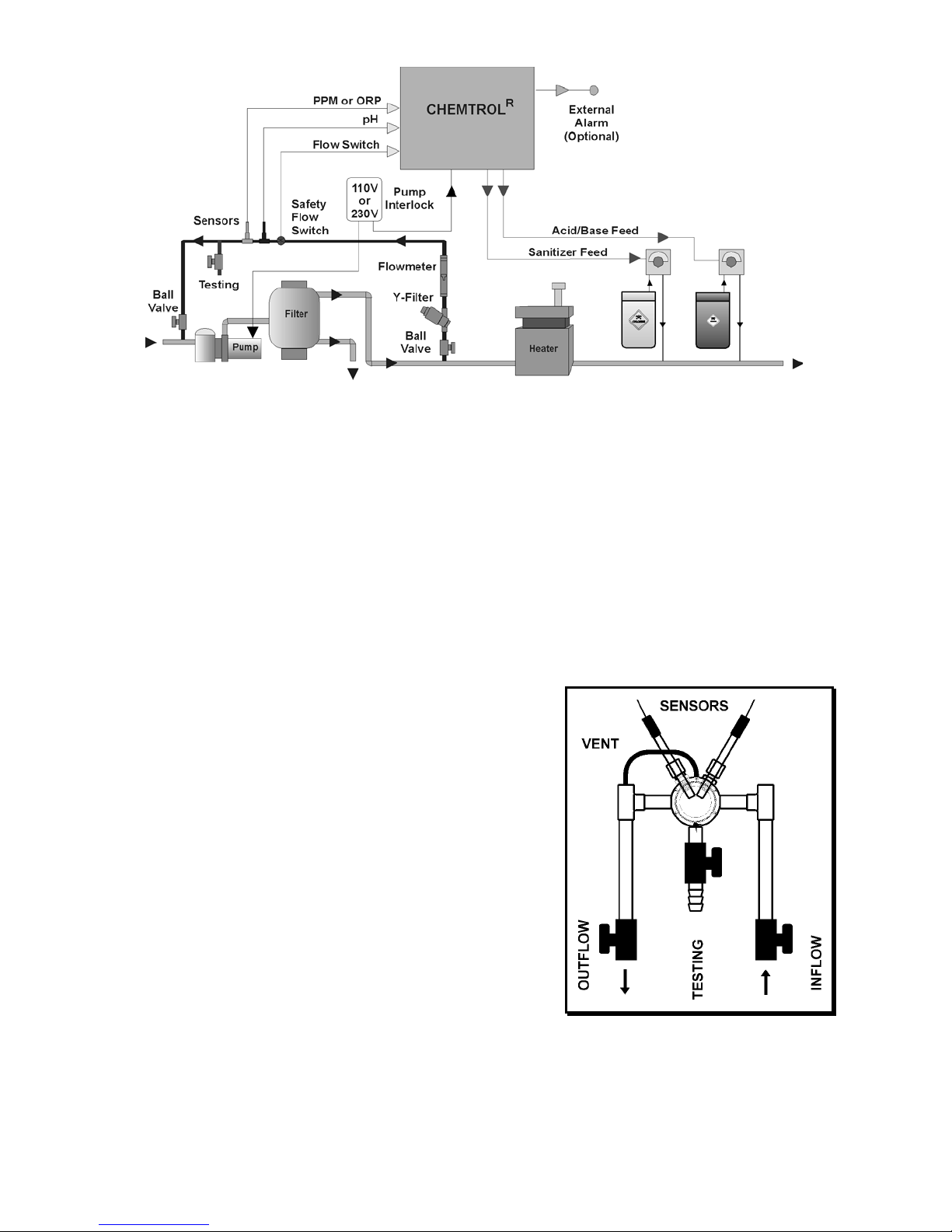
Mount the controller cabinet as shown in Figure 2 on a wall in a
secure location:
•more than 10' (3 m) away from the water edge to
comply with electrical code requirements,
•if possible, not more than 10' (3 m) of the main
recirculation line or of the bypass line. The sensors
come with standard 10-foot (3-m) cables. If needed,
you can order 25 or 50-ft BNC extension cables from
your dealer.
•not exposed to direct sunlight,
•easily accessible to maintenance personnel,
•if possible in a separate room, or in a well- ventilated
room as far away as possible from corrosive chemicals
and storage tanks,
•at a safe distance from power transformers, pump
motors or high voltage power lines
•safe from unauthorized access or vandalism.
SENSOR INSTALLATION
Save the sensor caps for storage or shipping of the sensors.
When in storage or shipping, add salt water in the cap to keep the
sensors from drying out. During winter, store the sensors above
freezing temperature.
The sensors can be mounted three different ways:
•directly on the main recirculation line (Figure 2) (2 in.
pipe only),
•on a 1/2 in. bypass line as shown Figure 3,
•even better, in a sensor cell mounted on the bypass line
(Figure 5).
MAIN LINE INSTALLATION
On smaller installations (2 “ pipe diameter), the sensors can be
mounted directly on the main recirculation line (Figure 2).
Use only the 2x2x1/2 in. SST reducing tees without reducers
(Figure 3). Do not install the sensors near an elbow or a
constriction where there might be excessive turbulence.
Install the tees after the pump and filter. Insert the sensor tip
down so that the tip is about 1/4 inch (1 cm) in the water. The
sensors should be readily accessible for servicing but not
exposed to physical damage.
Tighten the compression fitting by hand only to avoid breaking the
internal glass tube in the sensors. Do not use a wrench!
Figure 2 - Installation with Sensors on Main Line
Figure 3 - Sensor in PVC Tee
MAN250/04 Page 5
BYPASS LINE INSTALLATION
To facilitate installation of the sensors and to assure a smooth
and steady flow of water by the sensors, it is recommended to
install the optional Bypass Line Assembly (P/N BPL-0.5). As
shown in Figure 4, it includes:
- two (2) compression gland fittings (1/2" MPT) for the
sensors,
- two (2) PVC tees (1/2" SST),
- one (1) in-line Y-filter (3/4" MPT),
- one (1) in-line flowmeter (1/2" FPT),
- a rotary safety flow switch (1/2" FPT),
- two (2) ball valves (1/2" SxS) for flow adjustment and for
isolating the bypass line during backwashing of the filter and
other maintenance operations,
- one (1) labcock (1/2" SxS) for water sampling and testing.
The Bypass Line Assembly should be installed exactly as shown
on Figure 4. In particular, make sure to install the flowmeter in a
vertical position and to install the flow switch downstream of
(after) the sensors to assure a smooth flow of water near the
sensors.
SENSOR CELL
For additional ease of installation and maintenance, it is also
recommended to mount the sensors in the optional Flow Cell,
Assembly as shown in Figure 5. It includes:
•the sensor cell with air vent and clear cover,
•two (2) compression fittings for the sensors,
•one (1) water sampling tap
•two (2) ball valves for controlling the water flow in and out.
WATER FLOW
Proper flow of water past the sensors is essential to obtaining
good readings.
To ensure proper water flow, make sure that the bypass line is
properly connected. As shown in Figure 4, the intake side should
be on the effluent side of the recirculation system, i.e. after the
filter. The return side should be to a low-pressure area - such as
the vacuum side before the recirculation pump, or downstream
after the heater, or atmospheric pressure in the pit of a vacuum
sand filter or balancing tank.
To check the water flow in the bypass line, start the main
recirculation pump. Open both the intake and the return valves
on the bypass line and read the flow rate on the flowmeter. It
should be in the middle of the range, i.e. about 2-3 gpm (about 8
to 12 l/min). If the water flow is too high, you can turn down the
valve on the RETURN SIDE of the bypass line. If there is no
water flow, replumb the bypass line as shown on the schematic.
NOTE: Most common installation problems with bypass line
installations are caused by faulty hydraulics.
Figure 4 – Installation with Bypass Line Assembly
Figure 5 - Flow Cell Assembly

MAN250/04 Page 6
ELECTRICAL
Make sure to follow local electrical codes.
SEE TERMINAL BLOCK WIRING BELOW.
Always interlock the controller with the timer on the main
power supply (see Figure 2) to prevent injection of chemicals
when the recirculation pump is not running.
To prevent electrical shock, make sure that the power is
disconnected before opening the cabinet.
The Mother Board is mounted behind the front panel and the
Power Board (Figure 6) in the back of the controller.
VOLTAGE
The operating voltage is factory set for 110, 230 or 24 VAC.
Make sure to check the voltage before installation to avoid
damage to the control board and void the warranty. 110 V units
have a power cord with a 3-prong plug. 230 V units have bare
wires. 24 V units do not have a transformer. You can also check
Jumpers JP5 on the Power Board (Figure 6).
All outputs are the same as the input voltage.
PPM BATTERY (Models 235/255)
The PPM sensor is connected to the Mother Board with its own
9 V battery. Replace the battery if the voltage falls below 7.5 V.
REMOTE ALARM
The remote alarm is connected through the terminal block as
shown below. It can be used to activate a remote alarm such as
a light, a buzzer, or a bell, or even an automatic telephone dialer
with voice messaging capability.
The Alarm Jumpers JP6 (Figure 6) are normally set for a HOT
(powered) contact with two jumpers in the 1-2 and 3-4 positions.
For a dry (N.O.) contact, set one jumper only in position 2-3.
FLOW SWITCH
Note: with a bypass line, a Safety Flow Switch is
absolutely required to prevent accidental feeding of
chemicals if the line is shut off or obstructed.
The rotary paddlewheel flow switch connects to the controller
terminal block as shown below using the + 5V power input. DO
NOT CONNECT TO HIGH VOLTAGE.
A blade flow switch uses a dry contact that connects as shown
below to interrupt the power output. Make sure to orient the flow
switch in the direction of flow.
SETUP MENU
Upon startup, the Setup Menu is displayed. You can also recall
it at any time by pressing both arrow keys simultaneously.
ACID/BASE FEED
The Setup Menu first displays PHF (pH Feed) and either AC for
Acid Feed (default value) or bA for Base Feed. Press either
arrow to change the setting.
Acid Feed is used for all basic (alkaline) sanitizers: liquid chlorine
(sodium hypochlorite NaOCl) or dry chlorine (calcium hypochlorite
Ca(OCl)2). Base Feed is used only for acidic sanitizers (trichlor
tablets).
SANITIZER/pH INTERLOCK
The Setup Menu then displays IL for Interlock and either 0 for
OFF or 1 for ON (default value).
The Sanitizer/pH Interlock is a safety feature designed to
deactivate the sanitizer feed when the pH is out of range. This is
particularly important with liquid chlorine, a strong basic chemical
that raises the pH of the water.
SAFETY FLOW SWITCH
The Setup Menu then displays FLO for Flow Switch with either 0
for OFF or 1 for ON (default value).
TERMINAL BLOCK WIRING
HOT CMN GND + 5V
Red
SIG
White
GND
Black SIG GND HOT CMN GND HOT CMN GND HOT CMN GND
SANITIZER FEED PADDLE WHEEL FLOW
SWITCH POWER IN ALARM ACID/BASE FEED
Figure 6 – Power Board
MAN250/04 Page 7
CHEMICAL FEEDERS
Make sure to inject all the chemicals downstream of the
sensors to avoid false readings, and downstream of all equipment
(pump, filter, heater) to avoid corrosion.
CHEMICAL FEED PUMPS
Install the feed pumps for liquid chlorine, calcium hypochlorite or
dichlor solutions as shown in Figure 2, according to the
manufacturer’s instructions.
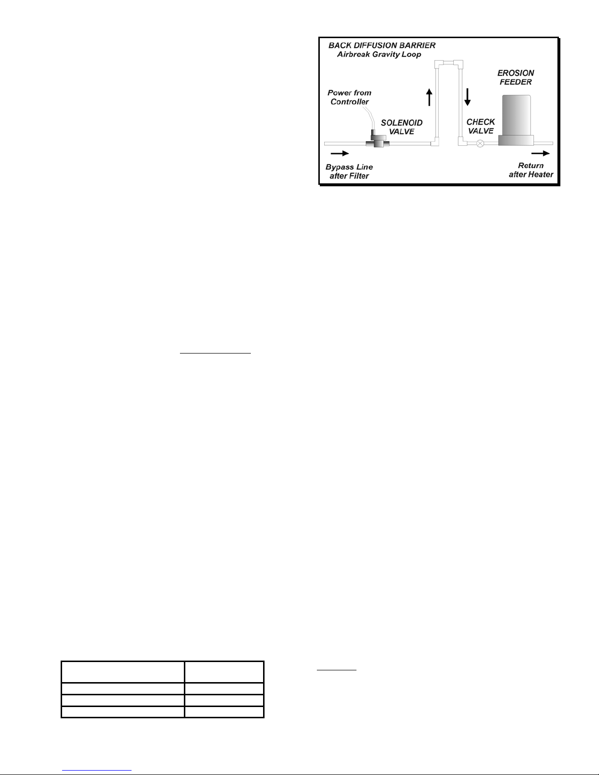
EROSION FEEDER
With an erosion feeder for bromine or chlorine tablets, install a
solenoid valve on the intake side of the bypass line to the erosion
feeder as shown in Figure 7.
OPERATION
PPM SENSOR CONDITIONING (Models 235/255)
IMPORTANT: DO NOT CONNECT THE PPM SENSOR before
the conditioning procedure is completed. Warranty may be void
if sensor is powered without proper conditioning.
Before using the PPM sensor for the first time – or after long
storage in air – it is important to hydrate the sensor. Remove the
sensor cap and place the sensor for at least 30 minutes in water
containing a small amount of chlorine without connecting it to the
controller.
Please note that the sensor’s time response for accurate chlorine
reading could take up to 30 minutes after first hydration and up to
15 minutes to stabilize after each water chemistry change.
SENSOR CALIBRATION
No calibration is required for the ORP sensor.
To calibrate the PPM and pH sensors, test the water with a
reliable, fresh test kit (DPD and Phenol Red). Note the values
and compare to the display values. Re-calibrate if needed, as
follows:
- press [CALIBRATION],
- press [PPM] or [pH]: the display flashes,
- use the [UP] and [DOWN] arrows to adjust the value,
- press [CALIBRATION] again to save the new value.
GAIN FACTOR (Models 235/255)
If the signal of the PPM sensor is too low due to excessive
cyanuric acid or other contaminants, the gain of the amplifier can
be increased in the Setup Menu.
Start the Setup Menu by pressing both arrows simultaneously.
When the display shows GF for Gain Factor, select 1, 2 or 4
depending on the cyanuric level.
CYANURIC ACID LEVEL
(ppm or mg/l)
GAIN FACTOR
GF
0-20 1x
20-60 2x
60 + 4x
CONTROL SETPOINTS
The PPM setpoint is factory set at 1.0 ppm.
The ORP setpoint is factory set at 700 mV, which is
recommended to maintain water quality by killing germs and
bacteria. There is no need for ORP calibration.
The pH setpoint is factory set at 7.5, which is recommended for
pool and spa applications.
To change a control setpoint:
- press [SETPOINT],
- press [PPM], [ORP] or [pH] : the display flashes,
- use the [UP] and [DOWN] arrows to adjust the setpoint,
- press [SETPOINT] again to save the new value.
OVERFEED SAFETY TIMERS
The internal safety timers are designed to alert the operator in
case of overfeeding of chemicals as a result of mechanical or
electronic failure or empty containers.
The timers are factory set at 15 minutes for PPM or ORP and 5
minutes for pH. This is normally sufficient to reach the setpoint.
At that time feeding stops and the timer resets to zero. If the
limit is reached however, the feeder is deactivated, the alarm
turned on and the display flashes the overfeed time. The
operator should then check the chemical feeders, feed lines and
tanks. After correcting the problem, the safety timer is reset by
switching the feed mode to OFF and then back to AUTO.
To change the limits of a safety timer:
- press [SAFETY TIMER],
- press [ORP], [PPM] or [pH] : the display flashes,
- use the [UP] and [DOWN] arrows to adjust the value,
- press [SAFETY TIMER] again to save the new value.
CAUTION: Increasing the limit on a safety timer may cause
overfeeding of chemicals.
Figure 7 - Erosion Feeder Installation
MAN250/04 Page 8
OUT-OF-RANGE ALARMS
The out-of-range alarms are factory set at 650 to 900 mV for
ORP, 0.3 to 6.0 for PPM and 7.0 to 8.0 for pH. If the ORP or PPM
readings are below the low limit, the red LED alarm flashes but
sanitizer feed continues.
If the pH limits are exceeded, the red LED alarm flashes and all
feeders (pH and sanitizer) are deactivated - unless the
sanitizer/pH interlock is defeated (see below).
To change an alarm limit:
- press [LOW LIMIT] or [HIGH LIMIT],
- press [PPM], [ORP] or [pH]: the display flashes,
- use the [UP] and [DOWN] arrows to adjust the value,
- press [LOW LIMIT] or [HIGH LIMIT] again.
CAUTION: Increasing the out-of-range limits may cause
overfeeding of chemicals.
FEED MODE
The feed mode for the sanitizer or pH can be set to OFF, Manual
or Automatic. To select the desired feed mode, press [PPM],
[ORP] or [pH] until the corresponding LED indicator light is
illuminated. There is a short delay before activation. (Note:
Holding the switch for more than 5 seconds resets the setpoint
and calibration for [PPM], [ORP] or [pH] to original factory
values).
.
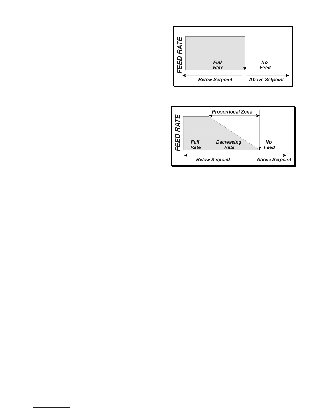
PROPORTIONAL FEED
There are two ways to control the feed rate.
In standard ON/OFF control (Figure 8), the feed rate remains
constant until the setpoint is reached, whereupon it stops.
In the Proportional Zone, activation of the chemical feeder is
based on 1-minute cycles with varying ratios of ON and OFF feed
times. As the sensor reading approaches the setpoint value, the
ON portion of the cycle decreases progressively. During the OFF
portion, the feed light flashes continuously to indicate that the
controller is under proportional control.
In proportional control (Figure 9), the feed rate decreases
progressively as it approaches the setpoint. Proportional control
is particularly useful to avoid overfeeding of chemicals in small
bodies of water.
CONTROLLER RESET
The CHEMTROL®controller saves all user-defined values as
well as factory defaults in its internal non-volatile memory.
Therefore, user-modified setpoints and acid/base feed modes will
not be lost in the event of power failure and the factory default
values can be restored at any time.
To reset the setpoint and calibration values to the original factory
values, press and hold [PPM], [ORP] or [pH] for 5 seconds.
STARTUP
DEFAULT PARAMETERS
PPM ORP pH
Setpoint 1.0 ppm 700 mV 7.5
High/Low Alarms 0.3/6 ppm 650/900 mV 7.0/8.0
Overfeed Safety Alarm 15 min. 15 min. 5 min.
Proportional Bandwidth 1% 1% 1%
AUTOMATIC CONTROL
1. Run the recirculationpump with both sensors in line at least 30
minutes to stabilize the sensor readings.
2. Turn the controller on. The displays will show:
a. the software version number,
b. [pHF] with [AC] for Acid feed or [bA] for Base feed,
c. [IL] with 0 or 1 if the sanitizer/pH interlock is ON,
d. [FLO] with 0 or 1 if the flow switch is ON.
d. [Gn] with 1, 2 or 3 for the PPM Sensor gain (Models 235
and 255 only),
e. the sensor readings.
3. Press [ORP] or [PPM] until the feed control light is on AUTO.
4. Press [pH] until the feed control light is on AUTO.
5. After 30 minutes, test the pH of the water with a Phenol Red
test kit. Adjust the pH calibration if needed.
6. Test the free chlorine or bromine ppm in the water with a DPD
test kit. Adjust the PPM or ORP setpoint if required.
7. Test the water regularly as required by local health authorities.
Figure 8 - ON/OFF Control
Figure 9 - Proportional Control

MAN250/04 Page 9
MAINTENANCE
The CHEMTROL®controller is virtually maintenance free. The
enclosure and front panel can be cleaned with a soft cloth
moistened with a mild soap and water solution or a glass cleaner.
Do not use abrasives or harsh chemicals.
GENERAL MAINTENANCE
For commercial and public pools, it is important to test and record
the water chemistry readings in compliance with Health
Department requirements using a good quality manual test kit.
Adjust the pH, ORP or PPM calibration and setpoint as required.
It is important to note that changes in pH, cyanuric acid
concentration, TDS (total dissolved solids), and use of additional
or alternative sanitizers will all impact the primary sanitizer
residual level in comparison to ORP. To maintain a consistent
sanitizer residual in parts-per-million (ppm), adjust the ORP
setpoint as required.
EFFECT OF CYANURIC ACID
Increasing cyanuric acid levels reduce the concentration of free
chlorine HOCl in water. This affects the effectivity of the sanitizer,
as shown by reduced readings for ORP (Model 250) or PPM
(Model 255).
The controller reacts by adding more chlorine to compensate for
the reduced effectivity. The only remedy is to replace all or part
of the water until the cyanuric acid level is reduced.
PPM SENSOR TESTING (Models 235/255)
To test the PPM sensor, use a DC Voltmeter and connect it to the
HOCl and Ground terminals on the Mother Board, with the PPM
sensor in chlorinated water. You should read 2.6 V or higher.
PPM BATTERY (Models 235/255)
You should test the 9 V battery on the Mother Board. Replace it
if the voltage falls below 7.5 V.
NO PPM SENSOR CLEANING (Models 235/255)
Do not clean the PPM sensor. Cleaners will damage the
membrane and void the warranty.
ORP AND pH SENSOR TESTING
To test the sensors on line, carefully add a small amount of white
vinegar or dilute acid solution in the skimmer. After a few
minutes:
- the pH reading should go DOWN.
- the ORP reading should go UP.
If you still get no response or a sluggish response, clean or
replace the sensors as soon as possible.
For additional testing, use the PORTA-PROBE II (Figure 10)
Portable Tester, as shown on the next page.
ORP AND pH SENSOR CLEANING
The sensor tips must be kept clean and free from chemical
deposits and contamination to function properly. After saturation
in pool or spa water, the sensors may need to be cleaned on a
weekly or monthly basis depending on the water quality and other
facility-specific characteristics. Slow response and inconsistent
readings are indications that the sensors are in need of cleaning.
To clean a sensor, carefully remove it from the compression
fitting. Clean the tip of the sensor with a mild liquid detergent
(Joy, etc.) solution. Rinse with fresh water and soak the sensor in
a mild acid solution for five minutes. Rinse with fresh water and
reinstall the sensor.
SENSOR REPLACEMENT
For optimum controller performance, always use genuine
CHEMTROL®replacement sensors. For preventive maintenance
it is also recommended to replace the sensors on an annual basis
or as performance diminishes.
SENSOR STORAGE
Extended exposure to atmospheric conditions will cause the ORP
and pH sensor tips to dry out.
The PPM sensor should be stored dry and electrically
disconnected.
Always remove and properly store the sensors if the pool or spa
is to be winterized or inactive. Store the sensors with the original
cap provided, making sure that each cap is filled with the original
storage solution or salt water. If the storage containers have
been misplaced, store the sensors individually in small glass or
plastic containers with clean water covering the sensor tips.
WINTERIZING
The sensors should be prepared for storage as outlined above
and protected from freezing. Although the controller is designed
to withstand a broad temperature range, winter storage in a
secure location at normal room temperature is recommended.

MAN250/04 Page 10
PORTABLE TESTER
The PORTA-PROBE II (Figure 10) is a battery-operated portable tester/signal
generator designed to test the ORP and pH sensors and to generate calibrated
signals to test the controller. It is supplied with a 9V battery and a pair of shielded
cables with BNC connectors.
The PORTA-PROBE II is not used to calibrate the sensors. This should be done
with a chemical test kit, such as DPD for Free Chlorine and Phenol Red for pH.
It can also be used to test the TDS and Temperature sensors on the CHEMTROL®
PC or CT controllers.
ORP SENSOR TESTING
Set the Mode Switch to TESTING. Connect the ORP sensor to the ORP BNC
connector on the tester. Turn the Selector Knob to ORP.
Place the sensor in balanced water (pH = 7.5 / PPM = 1.0 Cl). You should get an
ORP reading within 650 to 750 mV.
Place the sensor in an acid solution. You should get a HIGH POSITIVE reading.
Place the sensor in a BLEACH (liquid chlorine) solution. You should get a LOW
POSITIVE reading.
pH SENSOR TESTING
The PORTA-PROBE II shows actual pH sensor readings in millivolts, as shown on
the Table on the right.
Set the Mode Switch to TESTING. Connect the pH sensor to the pH BNC connector
on the tester. Turn the Selector Knob to pH.
Place the pH sensor in nearly neutral water (pH = 7.5). You should get a pH reading
of about -30 mV.
Place the sensor in an acid solution. You should get a HIGH POSITIVE reading.
Place the sensor in a BLEACH solution. You should get a HIGH NEGATIVE
reading.
The linear scale on the right shows the conversion of millivolt readings into pH units.
ORP AND pH SIMULATION
Set the Mode Switch to SIMULATOR.
Use the two coaxial cables to connect the BNC connectors on the tester to the
respective BNC connectors on the controller.
Set the Selector Knob to either pH or ORP Simulator. The readings on the controller
should match the readings of the tester display (unless offset by calibration of the
pH probe).
The outputs of the ORP and pH simulators can be adjusted with the two small knobs
located below the digital display. The ORP range is 0 to 1,000 mV.. The pH range
is -180 to + 180 mV (10 to 4 on the pH scale). These outputs can be used to test
for proper operation of the feed and alarm features of the controller.
NOTE 1: Due to signal stabilization, the readings on the controller may take up to
10 seconds to reach full value.
NOTE 2: ORP and pH signals can be generated simultaneously but only one signal
is displayed.
pH Scale
mV pH
+420 0
+30 6.5
07.0
-6 7.1
-12 7.2
-18 7.3
-24 7.4
-30 7.5
-60 8.0
-90 8.5
-420 14.0
Figure 10 - Portable Tester

MAN250/04 Page 11
TROUBLESHOOTING
No lights on. 1. Check the circuit breaker and/or receptacle for proper operation. Connect to functional
grounding-type GFCI protected power source.
2. Check for a damaged power connector.
3. Check internal fuse (1A slow blow) marked F7 on Power Board.
Alarm lights and buzzer
on.
1. Verify that the filtration system is functioning properly, water flow is adequate and water chemistry is
in balance.
2. Verify that sensor and power cables are properly connected to the respective connectors on the
controller.
3. Check the operation of the chemical feeders (pumps or erosion feeder).
4. Verify that the (optional) flow sensor is properly installed.
Illogical value displays.1. The sensor cable connections may be reversed. Verify that the sensor cables are properly connected
to their respective BNC connectors on the controller unit.
2. Verify that the filtration system is functioning properly, the water flow is adequate, and the water
chemistry is in balance.
No Chemical feed.
No Sanitizer feed.
1. Check FLO setting in Setup Menu and safety flow switch on bypass line if applicable.
1. Make sure the AUTO feed light is on.
2. Check the setpoint.
3. Check relay fuse (5A slow blow) marked F1 and F2 on Power Board.
No Acid/Base feed.1. Check pHF setting in Setup Menu for Acid or Base feed.
2. Make sure the AUTO feed light for pH is on.
3. Check the pH setpoint.
4. Check pH relay fuse (5A slow blow) marked F3 and F4 on Power Board.
Chlorine or bromine
residual too high or too
low.
1. Remember that the pH, cyanuric acid concentration, total dissolved solids, and use of additional or
alternative sanitizers will all impact the sanitizer residual level in comparison to ORP. Consider the
impact of any chemicals recently added to the pool or spa.
2. Check and adjust the setpoint.
pH requires frequent
calibration.
1. Clean or replace the sensor as outlined in the maintenance section.
Inconsistent or slow
readings.
1. Verify that the sensor cables are properly connected to their respective BNC connectors on the
controller unit.
2. Clean the sensors as outlined in the maintenance section.
3. Check to verify that all the electrical equipment in the facility pump room is properly grounded.
4. Replace the sensors if needed.
Chemical feeder runs
continuously.
1. Make sure the AUTO feed mode is selected.
2. Verify that the chemical feeders are properly connected to their respective connectors on the
controller unit.
pH or Sanitizer
overshoots setpoint.
1. Increase the width of the proportional zone.
2. Check the dilution of sanitizer or acid/base solution.
pH or Sanitizer does not
reach setpoint.
1. Decrease the width of the proportional zone.
2. Increase the concentration of sanitizer or acid/base solution.
3. Check chemical feeders for proper operation.
TABLE OF FIGURES
Figure 1 - Equilibrium of Free Chlorine.......................................................................................................................................................3
Figure 2 - Installation with Sensors on Main Line .......................................................................................................................................4
Figure 3 - Sensor in PVC Tee ....................................................................................................................................................................4
Figure 4 – Installation with Bypass Line Assembly .....................................................................................................................................5
Figure 5 - Flow Cell Assembly ....................................................................................................................................................................5
Figure 6 - PC Board....................................................................................................................................................................................6
Figure 7 - Erosion Feeder Installation.........................................................................................................................................................7
Figure 8 - ON/OFF Control .........................................................................................................................................................................8
Figure 9 - Proportional Control ...................................................................................................................................................................8
Figure 10 - Portable Tester.......................................................................................................................................................................10

MAN250/04 Page 12
PARTS LIST
MB250/255 Mother Board for CH250 or CH255 (specify voltage)
PB250/255 Power Board for CH250 or CH255 (specify voltage)
PPM PPM sensor with 10-ft BNC cable
ORP ORP sensor with 10-ft BNC cable.
pH pH sensor with 10-ft BNC cable.
PKT-2.0 Set of two (2) PVC tees and compression fittings for 2 in. (50 mm) line.
PKT-1.5 Set of two (2) PVC tees and compression fittings for 1 1/2 in. (37 mm) line.
OPTIONS
BPL-0.5 1/2 in. bypass line assembly with Y-filter, flowmeter, safety flow switch, two (2) shutoff valves and sampling tap.
PWFS Rotary paddle-wheel safety flow switch.
FCA Machined transparent polycarbonate flow cell assembly for sensors.
XC25 Sensor cable extension with BNC connectors, 25-ft (8 m).
XC50 Sensor cable extension with BNC connectors, 50-ft (16 m).
DIAL Telephone dialer with voice messaging.
SPECIFICATIONS
Cabinet Polystyrene (9.5x7.25" or 23.5x18 cm)
PPM Display 0 to 10 ppm
ORP Display 0 to 999 mV
pH Display 0 to 14
PPM Setpoint 0 to 10 ppm
ORP Setpoint 250 to 950 mV
pH Setpoint 4.5 to 9.5
PPM Accuracy 0.1 ppm
ORP Accuracy +/- 5.0 MV
pH Accuracy +/- 0.1 pH
Feed Controls Off / Manual / Automatic / Proportional
pH Feed Acid or Base Feed.
Safety Systems Visual and Remote Alarms
Control Comprehensive Diagnostic Self-Test
PPM Output 5 Amp/120 or 230 VAC
ORP Output 5 Amp/120 or 230 VAC
pH Output 5 Amp/120 or 230 VAC
Remote Alarm Dry contact for audio, visual or telephone dialer
Input Power 0.25 A at 120 or 230 VAC (exclusive of pumps)
This manual suits for next models
3
Table of contents
Other Chemtrol Controllers manuals


