Mueller IOSBUS Ammonia User manual

1
Operation Manual
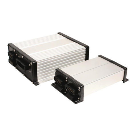
IOSBUS Ammonia Liquid Fertilizer Controller
Last Update: 6/16/2016
ME0112000-IN
Read and follow this operating
instructions.
Keep this operating instructions for
future reference.

2

3
1 For Your Safety 5
1.1 Basic Safety Instructions 5
1.2 EC Declaration of Conformity 6
1.3 Handling Ammonia Safely 6
1.4 Intended Use 6
1.5 Layout and Meaning of Warnings 7
1.6 Layout and Meaning of Alert Messages 8
1.7 De-pressuring the Control System 9
2 About these Operating Instructions 10
2.1 Illustrations in these Operating Instructions 10
2.2 Layout of Operating Instructions 10
2.3 Layout of References 11
3 Product Description 11
3.1 General Functions 11
3.2 InformationontheIdenticationLabel 12
4 Basic Control Principles 13
4.1 Switching on the ISOBUS ECU 13
4.2 Switching off the ISOBUS ECU 13
4.3 ISOBUS ECU symbol on a Display 13
4.4 Run Screen 14
4.4.1 Tank Display Area 15
4.4.2 Implement Display Area 16
4.5 Operating the Valves 18
5 Preparing the ISOBUS ECU for Use 19
5.1 Whenshouldyoucongurewhat? 19
5.2 ImplementConguration 19
5.3 Enter the Fill Level in the Tank 21
5.4 Speed Signal 24
5.4.1 Tractor Wheel Speed 24
5.4.2 Radar 25
5.4.3 Simulated (Demo) Speed 26
5.5 ConguringSections 26
5.5.1 Entering the Number of Sections 26
Table of Contents

4
5.5.2 Inputting the Number of Knives per Section 27
5.5.3 Inputting the Implement Geometry 27
5.6 Calibrating the Flow Meter 29
6 UsingtheISOBUSECUintheeld 31
6.1 Setting Rate 31
6.2 Starting Application 31
6.3 Stopping Application 33
6.5 Documenting Work Results 33
7 Road Mode 34
8 Troubleshooting and Technical Data 35
8.1 Harness Diagrams 36
8.2 Cable Pin Diagrams 37
8.3 Diagnostics 39

5
For Your Safety
Basic Safety Instructions 1
1 For Your Safety
1.1 Basic Safety Instructions
Please read the following safety instructions carefully before operating the
productforthersttime.
Working:
• Before leaving the vehicle’s cab, ensure that all automatic mechanisms
are deactivated or that manual mode is activated.
• Always check the system thoroughly before the season starts.
• Do not open the master valve if the injection knives are out of the soil.
• No one should remain in the proximity of the tractor or the application unit
during work.
• Before driving on a public road, close all valves. For example, by
activating road mode. [➙33]
Instructions:
• Learn how to operate the ISOBUS Controller correctly. No one should
operate this before having read and understood these operating
instructions.
• Read and carefully observe all safety instructions and warning notices
in these operating instructions and in the instructions for connected
machines and devices.
• If any part of the operating instructions is unclear, ask your dealer or
Mueller-Electronics.
• Ensure that everyone in close proximity to the system has been trained
how to work with the application product properly.
Alterations to the product:
• Do not make unauthorized alterations to the product. Unauthorized
alterations or unauthorized use can place your safety at risk and affect the
lifespan or function of the product. All alterations which are not described
in the product documentation are forbidden.
• Do not remove any safety mechanisms or stickers from the product.
• The product does not contain any serviceable parts. Do not open the
housing.

6
1.2 EC declaration of conformity
This product has been manufactured in conformity with the following national
andharmonizedstandardsasspeciedinthecurrentEMCDirective
2004/108/EC:▪ENISO14982
1.3 Handling Ammonia Safely
Contact with anhydrous ammonia can lead to the following:
• death
• very hazardous thermal or chemical burns
• eye injuries or blindness
• suffocation or Injuries to the respiratory tract
To work safely with ammonia, please read all safety instructions and
safety-related information before using the system.
•Findoutfromyourdealerwhatsafetyrequirementsyoumustfulllin
order to be able to work safely with ammonia.
• Always wear protective equipment which is appropriate for working with
ammonia. These include: Face mask, protective glasses, chemical han-
dling gloves, protective clothing, breathing apparatus. Ask your dealer
about the proper equipment.
• Do not allow anyone who has not been trained to use the system.
•Ensurethattherinsingwatertanksarealwayslledwithcleanwater.
• Before opening a valve, always assume that it contains ammonia.
• Never stand into the wind when emptying the hose lines.
• Ensure that discharge outlets are not pointed towards a person.
• Before performing maintenance on the system, rinse out the ammonia.
Waitforsufcienttimetoallowtheliquidtoevaporate.
1.4 Intended use
The ISOBUS Liquid controller is intended exclusively for metering liquid on
agriculturalequipmentspecicallydesignedforsubsurfaceapplicationof
liquid in an agricultural operation.
The manufacturer cannot be held responsible for any installation or use of
the system that deviates from or exceeds the scope of intended use.
The manufacturer cannot be held liable for any personal injury or property
damage resulting from improper use. All risks involved in engaging in
improper usage, lie solely with the user.
Intended use is also understood to include adherence to the conditions for
operation and repair as prescribed by the manufacturer.
For Your Safety
Basic Safety Instructions
1

7
All applicable accident prevention regulations and all other generally
recognized safety, industrial, and medical standards, as well as, all road
trafclawsmustbeobserved.Anyunauthorizedmodicationsmadetothe
equipment will void the manufacturer’s warranty.
1.5 Layout and Meaning of Warnings
All safety instructions found in these Operating Instructions are composed in
accordance with the following pattern:
DANGER
This signal word identies high-risk hazards, which can cause death or the
most serious bodily injury, if not avoided.
WARNING
This signal word identies medium-risk hazards, which could potentially cause
death or serious bodily injury, if not avoided.
CAUTION
This signal word identies low-risk hazards, which could potentially cause
minor or moderate bodily injury or damage to property, if not avoided.
NOTICE
This signal word identies actions which could lead to operational
malfunctions if performed incorrectly.
These actions require that you operate in a precise and cautious manner in
order to produce optimum work results.
There are some actions that need to be performed in several steps. If there is
a risk involved in carrying out any of these steps, a safety warning will appear
in the instructions themselves.
Safety instructions always directly precede the step involving risk and can be
identiedbytheirboldfonttypeandasignalword.
Example:
1. NOTICE! This is a notice. It warns that there is a risk involved in the
next step.
2. Step involving risk.
For Your Safety
Basic Safety Instructions 1

8
1.6 Layout and Meaning of Alert Messages
While working with the implement, an alarm message may appear. The alarm
messages have the following purpose:
Warn - They warn the operator when the current condition of the
implement can lead to hazardous situations.
Inform - They inform the operator that the current condition of the
implementisnotcorrectorthatitisincorrectlyconguredandcanlead
to problems during operation.
On the following diagram, you can see how the alarm messages are
structured:
For Your Safety
Basic Safety Instructions
1

9
1.7 De-pressurizing the Control System
DANGER
Ammonia under pressure
Death or serious physical injury
• Even when the pressure in the system is 0 psi, liquid ammonia can still
be present in the system. Ammonia can remain between the shutoff
valves and in lines which are lower than the rest of the system.
• Frost on any component is always an indication that liquid ammonia is
still evaporating. Even if no frost is apparent, this does not mean that the
ammonia has completely escaped.
To reduce the pressure in the system using the ISO Ammonia Controller, do
the following:
1. Close the master valve.
2. Switch off the job computer.
3. Close nurse tank valves and disconnect nurse tank from implement.
4. Lower the implement so that the injection knives are in the soil.
5. Switch on the job computer and open all section valves so that ammonia
can injection knives escape into the soil.
6. Towthedeviceacrosstheeld.
7. Continue driving until the pressure at manifolds reaches 0.
8. Slowly lift the implement out.
9. Keep a lookout at a safe distance for any signs of white vapor.
10.If you see vapor, lower the implement and wait for a few minutes. Lift the
implement again and check for vapor again.
11. If no more vapor is escaping, stop.
12.WARNING! Opening a bleed valve can allow residual ammonia to escape.
13.Open all of the bleed valves on the control system.
14.Check if frost appears on the plumbing. This means that there is still liquid
ammonia in the system.
15.Wait until the ammonia evaporates from the system. This evaporation can
lastanumberofdaysorweeks,dependingonthetemperatureandcong-
uration. The implement can be stored during this time.
16.If you want to disassemble the plumbing, please refer to the manufacturer’s
service instructions of the ammonia cooler for how to make these safe.
For Your Safety
Basic Safety Instructions 1

10
2 About these Operating Instructions
2.1 Illustrations in these Operating Instructions
The role of the diagrams on the software interface is to serve as a reference.
Theyhelpyouinndingyourwayaroundthesoftwarescreens.
In these instructions, “screens” refer to anything which appears on the
displays screen, with the exception of the function icons.
The information shown on the display is dependent on various factors:
• type of implement
•conguration
• status of all actuators and sensors
• model of the ISOBUS display
The screens on the display may therefore sometimes differ from those given
in these operating instructions.
The instructions were written for the operation of the job computer with
Mueller-Electronics display. When the job computer is operated using other
ISOBUS displays, the layout of the screens and the information displayed
can differ from the illustrations in these operating instructions.
2.2 Layout of Operating Instructions
The operating instructions explain step by step how you can perform certain
operations with the product.
We use the following symbols throughout these Operating Instructions to
identify different operating instructions:
Type of depiction Meaning
1.
2.
Actions that must be performed in succession.
Result of the action.
This will happen when you perform an action.
Result of an operating instruction.
This will happen when you have completed all steps.
Requirements.
In the event that any requirements have been specied,
these must be met before an action can be performed.
Operating Instructions
Illustrations & Layout
2

11
2.3 Layout of References
If any references are given in these Operating Instructions, they will appear
as:
Example of a reference: [➙8]
Referencescanbeidentiedbytheirsquarebracketsandanarrow.The
number following the arrow shows you on what page the chapter starts
whereyoucanndfurtherinformation.
3 Product Description
3.1 General Functions
The ISOBUS Liquid ECU, which performance is described in these operating
instructions, is used to control the precise application of liquid in agriculture.
The system is provided with the following functions:
• Determination and display of speed.
• Control of the application amount based on the speed and working width
of the implement used.
• Display of the current tank content.
• Automatic Section Control with an ISO Task Controller system.
This enables the automatic opening and closing of section valves in
order to prevent overlapping.
• Transfer of target rates from prescription maps.
•Closureofallvalveswhenthevehicleslowsbelowadenedspeed.
Regulation
In order for the ISOBUS ECU to control the application amount, a number of
componentsmustbeconnectedandcongured.
Certain valves are optional. When these are installed, however, they improve
the operation of the system.
Product Description
Regulation 3

12
Product Description
IdenticationLabel
3
1Tank with ammonia
2Safety Valve - This valve is not controlled by the job computer. This is an Aux. Master that is
used as a secondary shutoff if something happens to the job computer and the system needs to
be closed manually.
3Flow Meter - A sensor which determines the current ow and transmits this to the job computer.
4Control Valve - Valve, electrically controlled. Its opening angle controls the amount of ammonia
which is fed to the injection knives.
5Master Valve (optional) - Valve, electrically controlled. This can be opened and closed very
rapidly. This is used to close the line quickly.
6Section Valve (optional) - Valves, electrically controlled. These can be open or closed. These are
used to open and close the feed to individual sections.
3.2 InformationontheIdenticationLabel
OntheISOBUSECU,youwillndanIdenticationLabel.Thislabelprovides
all the information you need to clearly identify the product.
Have these details ready when you contact your dealer.

13
4 Basic Control Principles
4.1 Powering Up the ISOBUS ECU
You can switch on the ISOBUS ECU as follows:
1. Supply the ECU with power. This can be done in the following ways:
a) For ISOBUS tractors: Switch the tractor on using the ignition key.
b) For non-ISOBUS tractors: Switch on the display.
2. You have switched on the ECU.
4.2 Powering Down the ISOBUS ECU
Always switch off the ECU in the following situations:
•Whenyouhavenishedwork.
•Beforeyouleavetheeld.
• When someone approaches the implement.
You can switch off the ECU as follows:
1. Stop the tractor.
The ISOBUS ECU closes all the valves.
The work screen displays this icon:
2. Switch application on by pressing the Power icon.
The application indicators beneath the icon of the
implement are faded out:
3. Activate road mode by pressing the Road icon.
Alarm message appears: “Caution! Road mode is
active!”
4. Switch off the tractor at the ignition switch, and ensure
that the display is switched off.
ðYou have switched off the job computer.
4.3 ISOBUS ECU Symbol on a Display
You can recognize the ISOBUS ECU existence on your display by the
following icon:
Basic Control Principles
Powering the ECU 4

14
4.4 Run Screen
The work screen is always displayed during work and contains the most
important information. The work screen tells you the status of the implement
during work.
The Run Screen is divided into four areas:
1Speed Indicator
Information on speed
3Implement Display Area
Information on sections & performance
2Application Display Area
Information on regulation & tank content
4Product Display Area
Information on product ow
Function Icons on the Run Screen
Function icons are shown on the sides of the display. You can touch these
(on a touch-screen) or press a function key beside the icon (on a non-touch
display) to perform a function.
1
2
3
4
Basic Control Principles
Run Screen
4

15
Function icon Meaning
This opens a screen with counters.
This opens a screen into which you can enter the tank content. [➙21]
This opens screens in which you can congure the system. [➙17]
This activates Road Mode. [➙33]
This displays further function icons.
4.4.1 Tank & Rate Display Area
Thisareadisplaysinformationonthetankcontentandtheow.Certain
calculated predictions regarding areas and distances still to be worked
are also displayed here.
What information is shown on the display is dependent on how the
manufacturerhasconguredthejobcomputer.
1Control Channel Indicator
This icon indicates the control channel used
for the product control and product form. In
example above Control 1 and liquid form.
4 Tank Fill Level
The bar graph provides a visual indication of
the tank level.
2Actual Rate
This displays the actual As Applied rate
5 Tank Level
This area indicates the # of units of product
remaining in the product tank.
3Target Rate
This area will display the current Target
Rate as set by operator.
1
2 3 4
5
Basic Control Principles
Tank Display Area 4

16
4.4.2 Implement Display Area
1
2
345
6
1Which sections are applying.
2Tank number indicator.
3Area remaining based on tank level.
4Master ON/OFF Indicator.
5Performance in Area/hour.
6Rate has been adjusted from Default Rate. This
icon also appears briey when you press the
Increase Rate or Decrease Rate icons in Manual
Mode.
Basic Control Principles
Implement Display Area
4

17
The following illustrations show how the secions in the implement display
area can appear.
Display Section State
Section is switched off.
Section is manually switched off while the SECTION-Control application is working in
automatic mode.
As long as SECTION-Control is working in automatic mode, this section cannot be
switched on or off automatically.
Section is preselected.
Section is ready for application. Section is in Overlap
Section is preselected and the main section switch is switched on.
Section is applying.
Possible Section States:
The sections can be in four states. You can see the state of a section on the
work screen in the implement display area.
Basic Control Principles
Section States 4
Sections 1-4 are switched off. Section 5 is pre-selected and
applying.
Sections 1-4 are switched off. Section 5 is pre-selected but
not applying.

18
4.5 Operating the Valves
You can operate the valves directly using the display function keys. Work
Screen will default with icons for Master Control, Section Control and Rate
control.
Function Icon
Funtion
Sections Master Switch - Opens and closes the control valve fully. If a
master valve is installed, it is also opened and closed.
Rate Decrease - Decreases the rate with every button push by the preset
amount which was determined and set during the conguration setup.
Rate Increase - Increases the rate with every button push by the preset
amount which was determined and set during the conguration setup.
Automatic Mode - Undoes the manual changes to the rate.
Auto/Manual - When tapped, this button puts the system in manual mode.
This allows you to press the rate increase or rate decrease icons to manually
open or close the valve. Press the Auto/Manual icon again to return the
system to Automatic Mode. (see screen shot below)
Open or close valves if you have 4 or less sections.
Open or close valves if you have more than 4 sections.
Basic Control Principles
Operating Valves
4
Arrow #1 indicates that
Manual Mode has been
activated.
Arrow #2 shows the Rate
Increase icon appearing when
pressed.

19
5 Preparing the ISOBUS ECU for Use
5.1 Whenshouldyoucongurewhat?
Beforeusingthecultivatorforthersttime,youmustcongurethefollowing
settings:
5.2 ImplementConguration
1.PresstheCongurationicon:
TheConguration1screenappears:
You have to congure the following Chapter with more information
Implement parameters Inputting the implement parameters [➙17]
Implement dimensions Inputting the implement geometry [➙25]
Conguring the speed source Speed signal [➙22]
Sections Conguring sections [➙ 24]
Flow meter Calibrating the ow meter [➙27]
2.Selectthevalueoftheaparameterbypressingthedesiredeld.
The data input screen appears.
3. Enter the new value.
The new value appears on the display.
ConguringtheECU
ImplementConguration 5

20
CongurationParameters:
The list contains all parameters that can appear on the screen. The parame-
terswhichappearonyourdisplayaredependentonthetypeandcongura-
tion of your implement.
Target Rate
You can use this parameter to set how much product you want to apply. If
you are working with a prescription map, the value input here will be ignored.
The job computer works from the value on the prescription map.
Delta Target Rate
Thisnumberreectstheamountofchangetotherateeachtimeit’spressed.
Estimated Tank Pressure
Inputs the Tank Pressure value used for display only.
Application Type
Use this parameter to input what product should be taken onto account when
calculating the application amount.
NH3 Density
Thiseldisnotaparameter,butisratherdisplayedasavalue.Thisdisplays
the density of the ammonia. The density is dependent on the pressure that
you set in the Estimated Tank Pressure parameter. If the density of the am-
monia changes, the value of the Rate parameter also changes.
Press the icon with three dots to proceed:
TheConguration2screenappears:
ConguringtheECU
Setting Parameters
5
Table of contents
Other Mueller Controllers manuals
Popular Controllers manuals by other brands

Hinkley
Hinkley 980008 installation instructions

Resol
Resol DeltaSol C Plus Mounting, Connection, Operation, Troubleshooting, Examples

Greenheck
Greenheck MP-310 Installation instructions and use

TFA
TFA 47.3003 instruction manual

OPTi
OPTi ChromaCast 82C205 Preliminary Programmer’s Guide

EPC
EPC Epaco E10-0066 Installation and operation instruction

CentraLine
CentraLine EAGLEHAWK NX Product data

POL-EKO
POL-EKO SMART instruction manual

Alemite
Alemite 7504-1 Installation and service instructions

Gemas
Gemas Pool Control Mono Installation and instruction manual

LAE electronic
LAE electronic AT1-5 Instructions for use

ZIEHL-ABEGG
ZIEHL-ABEGG Ucontrol PXDM Series manual