ESE HD-206/SD User manual

142 SIERRA ST., EL SEGUNDO, CA 90245 USA (310)322-2136 FAX (310)322-8127 www.ESE-WEB.com
HD-206/SD
HD/SD SDI Time and Date Inserter
Operation and Maintenance Manual
Revision 1.2

Page i Revision 1.2
SAFETY INSTRUCTIONS
Please review the following safety precautions. If this is the first time using this unit, then read this manual before
installing or using the unit. If the unit is not functioning properly, please contact the ESE factory or system installer.
Failure to follow these safety instructions could result in injury to you or damage to the unit.
Be careful with electricity:
•Power outlet: To prevent electric shock, be sure the electrical plug used on the unit’s power cord matches the
electrical outlet used to supply power to the unit. Only connect the power cord to a power source that operates
between 90-264 VAC, 47 - 63 Hz. If option DC is ordered, only connect the power input to a power source that
operates between +12 to +35 VDC. If option UL is ordered, only connect the wall wart adapter to a power
source that operates between 90-264 VAC, 47 - 63 Hz.
•Power cord: Be sure the power cord is routed so that it will not be stepped on or pinched by heavy items.
•Power overloading: Avoid overloading electrical outlets or extension cords which otherwise could result in
electric shock or fire.
•Lightning: For protection from lightning or when the unit is left unattended for a long period, disconnect it from
the power source.
•Protect other equipment: Unplug the unit before connecting any other equipment. Connect all equipment to
the unit before plugging in any power cords to the power source.
WARNING!
TO REDUCE THE RISK OF ELECTRICAL SHOCK, UNPLUG THE UNIT BEFORE REMOVING THE COVER
REFER SERVICING TO QUALIFIED PERSONNEL
Also follow these precautions:
•Ventilation: Do not block any ventilation holes on the unit or place any heavy object on top of it. Blocking the
airflow could damage the unit. Arrange components so that air can flow freely around the unit. Ensure that
there is adequate ventilation to the unit wherever it is placed. Put the unit in a properly ventilated area, away
from direct sunlight or any source of heat.
•Overheating: Avoid stacking the unit on top of a hot component.
•Risk of Fire: Do not place the unit on top of any easily combustible material, such as paper, carpet or fabric.
•Proper Connections: Be sure all cables and equipment are connected to the unit as described in this manual.
•Object Entry: To avoid electric shock, never stick anything in the holes on the enclosure or remove the cover.
•Water Exposure: To reduce the risk of fire or electric shock, do not expose the unit to rain or any other source
of moisture.
•Keep the unit out of the reach of children or it may fall, causing personal injury or damage to the unit.
•Always disconnect the power cord from the power outlet when you are not using the unit. This reduces
your risk of electric shocks or fire.
•Always turn off the unit, disconnect it from the power outlet, and unplug all other cables from before
moving the unit. This reduces your risk of electric shocks or fire.

Page ii Revision 1.2
TABLE OF CONTENTS
1.0INTRODUCTION ......................................................................................................................................... 1
2.0INSTALLATION & OPERATION.................................................................................................................. 1
3.0ENCLOSURE............................................................................................................................................... 1
4.0STANDARD FEATURES............................................................................................................................. 1
4.1Front Panel............................................................................................................................................... 1
4.1.116 x 2 Character LCD.......................................................................................................................... 1
4.1.2USB Port.............................................................................................................................................. 1
4.1.3Front Panel Pushbuttons..................................................................................................................... 1
4.2Rear Panel ............................................................................................................................................... 2
4.2.1Power Module...................................................................................................................................... 2
4.2.2SDI Input.............................................................................................................................................. 2
4.2.3SDI Outputs......................................................................................................................................... 2
4.3Video Insertion ......................................................................................................................................... 2
4.3.1Two Windows...................................................................................................................................... 2
4.3.2Fonts and Colors................................................................................................................................. 2
5.0SETUP......................................................................................................................................................... 2
5.1MENU SELECTIONS............................................................................................................................... 2
6.0CONTROL PANEL SOFTWARE................................................................................................................. 5
6.1Product Information.................................................................................................................................. 5
6.2Window Settings ...................................................................................................................................... 5
6.3Main Settings............................................................................................................................................ 6
6.4Update Firmware...................................................................................................................................... 7
7.0OPTIONS..................................................................................................................................................... 7
7.1Available Options ..................................................................................................................................... 7
8.0SPECIFICATIONS....................................................................................................................................... 8
8.1General..................................................................................................................................................... 8
8.2Optional.................................................................................................................................................... 8
9.0FRONT AND REAR VIEWS........................................................................................................................ 9
10.0RoHS COMPLIANCE ................................................................................................................................ 10
11.0FCC NOTE................................................................................................................................................. 10
12.0WARRANTY .............................................................................................................................................. 10
13.0REVISION HISTORY................................................................................................................................. 10

Page 1 Revision 1.2
1.0 INTRODUCTION
The HD-206/SD is a High Definition (HD) and Standard Definition (SD) Serial Digital Interface (SDI) Time and
Date Inserter. An internal crystal maintains the time after it is set.
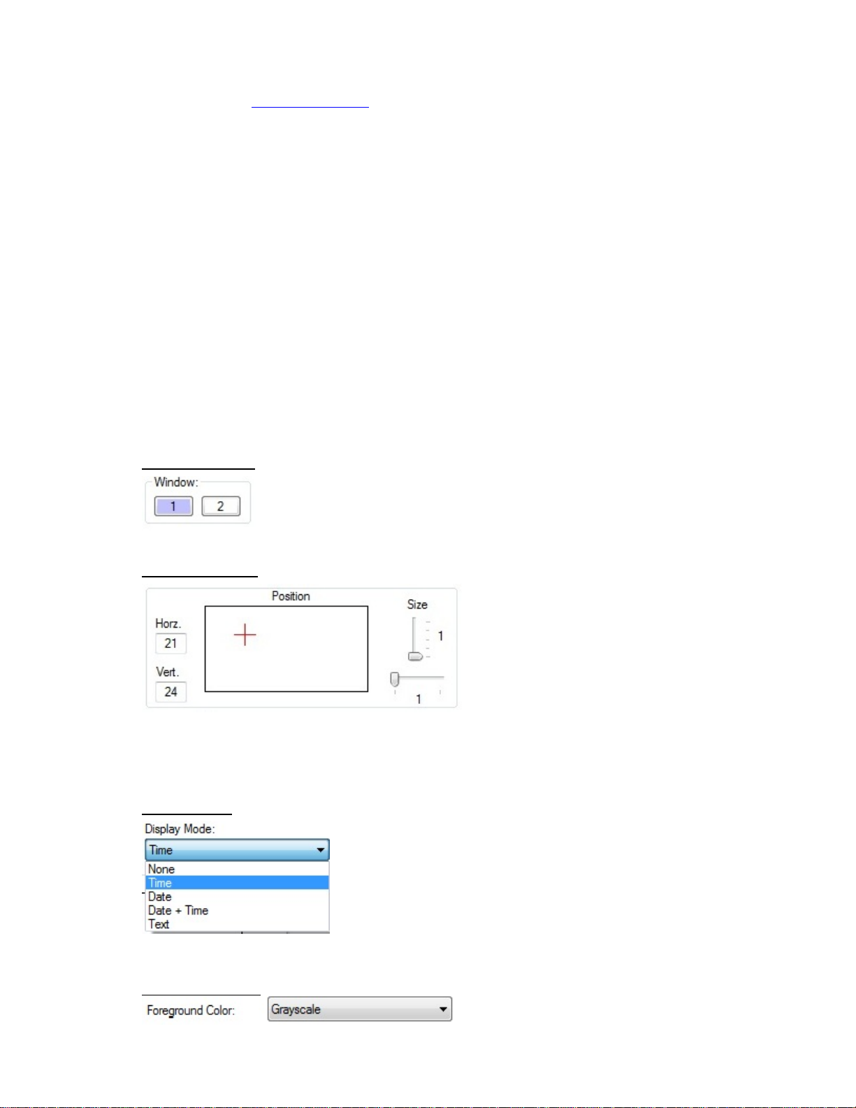
Time and date insertion is an integral part of the HD-206/SD. Time and date, date, time or up to 30 characters of
text may be superimposed onto the video in two independent windows, which may be individually blanked. Ten
different font sizes are available. Grayscale and six solid color fonts (red, orange, yellow, green, blue and violet)
are included.
The HD-206/SD accepts 1080i/60, 1080i/59.94, 1080i/50, 1080p/30sF, 1080p/29.97sF, 1080p/25sF, 1080p/24sF,
1080p/23.98sF, 720p/60, 720p/59.94 and 720p/50 digital video signals and automatically equalizes up to 250m of
Belden 1694A cable at 1.485Gb/s. The HD-206/SD equalizes up to 480m of Belden 1694A cable at 270Mb/s.
Embedded audio and other ancillary data signals are passed through the unit (HD mode only). Two HD/SD SDI
outputs are provided. The formats of the SDI outputs match the format of the SDI input.
All the features and the time of the HD-206/SD are set using the front panel pushbuttons or the PC Control Panel
software. The LCD menu selections and the Control Panel software are described in detail in sections 5 and 6,
respectively.
The unit is housed in a black anodized desktop enclosure (8” W x 1.6” H x 6.7” D). The power requirements for
the unit are 90 – 264 VAC, 47 – 63 Hz, 15 W maximum. A 2-amp fuse accessible from the rear panel.
2.0 INSTALLATION & OPERATION
Installation of the HD-206/SD requires connecting equipment to the HD-206/SD and setting up the HD-206/SD via
the front panel LCD menus or the PC Control Panel software. Plug the unit in to 117 VAC or 220 VAC. The front
panel LCD indicates that the unit is booting up, displays the current firmware version and then displays the time
and date. The time starts from 00:00:00 and the date starts from 2017/01/01 (Y/M/D).
Video connections to the HD-206/SD may be made at any time. Connect the HD or SD SDI source to the SDI
Input BNC. The HD-206/SD auto-detects whether video input signal is SD or HD. One device may be connected
to each SDI output BNC (two SDI outputs are provided).
After connections to the unit are made, the user should go through the LCD menus to set up the unit according to
the inputs connected to the unit. The menus are described in detail in section 5. Alternatively, the user may use
the PC Control Panel software to set the unit up. The PC Control Panel software is described in detail in section
6. The seconds can be adjusted by holding down the Up or Down arrow buttons when the Real Time Clock is
shown on the LCD. The seconds will advance or decrement at a rate of 5 ms/s.
Once the HD-206/SD is set up according to the user specifications, the unit is ready to use. If the settings are
changed via the LCD menu or Control Panel software, they are not made permanent for 30 seconds. Because of
this, the unit should not be turned off for 30 seconds after changes are made to the settings.
3.0 ENCLOSURE
The HD-206/SD is housed in a black anodized desktop enclosure that measures 1.6” high x 8" wide x 6.7” deep
(plus connectors). The ruggedized enclosure is constructed of aluminum.
4.0 STANDARD FEATURES
4.1 Front Panel
4.1.1 16 x 2 Character LCD
The front-panel 16 x 2 character LCD shows the status, time and date of the unit and is used
to display the menus.
4.1.2 USB Port
The USB port is used to interface the HD-206/SD with a PC. PC Control Panel software is
provided with the HD-206/SD. The Control Panel software allows the user to change settings
without having to use the front panel pushbuttons and LCD. The USB port is also used to
update the firmware for the HD-206/SD.
4.1.3 Front Panel Pushbuttons
Four pushbuttons are supplied on the front panel. The Left and Right pushbuttons are used to
navigate through the menus. The Up and Down pushbuttons are used to select the menu

Page 2 Revision 1.2
items available with each menu. Holding the Up and Down pushbuttons down advance and
decrement the seconds at a 5ms/s rate.
4.2 Rear Panel
4.2.1 Power Module
The power module on the rear panel accepts an IEC 320 three-wire line cord. A 2-amp fuse is
also part of the power module. The line cord must be removed to access the fuse.
4.2.2 SDI Input
The HD/SD SDI Input is accessible on a rear panel BNC.
4.2.3 SDI Outputs
Two identical HD/SD SDI outputs are provided on rear panel BNCs. One device may be
connected to each output. The output format is the same as the input format.
4.3 Video Insertion
4.3.1 Two Windows
The date and time, the date, the time or up to 30 characters of text can be superimposed onto
the video in two independent windows. The 30 characters of text can be superimposed onto
either or both windows. Both windows can be blanked if desired.
4.3.2 Fonts and Colors
Ten different font sizes are available. Grayscale and six solid color fonts (red, orange, yellow,
green, blue and violet) are included.
5.0 SETUP
The LCD and pushbuttons allow the user to set up the features of the HD-206/SD without using the Control Panel
software. The menus are traversed using the left and right arrow buttons. The user can browse the options
available for each menu by using the up and down pushbuttons. The last selection made when exiting a menu is
selected.
Important Note: When the user stops on a selection by using the up and down arrow buttons and moves on to
the next menu, that item is selected. If no buttons are pressed for 30 seconds while navigating the menus, the
current item is selected and the display reverts back to the time and date. If the settings are changed via the
menu or Control Panel software, they are not made permanent for 30 seconds. Because of this, the unit should
not be turned off for 30 seconds after changes are made to the settings.
The default LCD display shows the time and date. Characters before the time and date indicate what is displayed.
An example is shown below.
RTC 12:34:44
2017/01/01
This example displays the real time clock (RTC) time 12:34:44 and date 2017/01/01 (Y/M/D).
5.1 MENU SELECTIONS
The listings below show the menu title in bold followed by the selections available for that menu title along
with a description of each selection.
DAYLIGHT SAVING:
ON or OFF – Turn this setting ON to have the unit automatically adjust for Daylight Saving Time.
VIDEO HOUR:
12 or 24 – This selects 12 or 24 hour time format for the video display.
VIDEO DATE:
YEAR-MONTH-DAY – This selects the YEAR-MONTH-DAY format for the video display.
MONTH-DAY-YEAR – This selects the MONTH-DAY-YEAR format for the video display.
DAY-MONTH-YEAR – This selects the DAY-MONTH-YEAR format for the video display.
- TEXT DISPLAY -
This menu selection allows the user to set the text display. Use the up or down button to enter the text
entry screen. Use the left and right buttons to scroll to the desired position. Use the up and down
buttons to select the character. To move to the next menu selection, scroll left or right until the cursor
stops blinking and press the up or down button to exit the text entry screen.

Page 3 Revision 1.2
W1 DATA: (Window 1)
DATE+TIME – Displays the day and time.
DATE – Displays the date.
TIME – Displays the time.
NONE – The W1 line is blanked.
TEXT – Allows the user to display 30 characters of user specified text.
W1 HORIZ POS:
1 … 99 – Select a number from 1 to 99. 1 is the farthest left.
W1 VERT POS:
1 … 69 – Select a number from 1 to 69. 1 is at the top.
W1 HORIZ SIZE:
1 … 2 – Select a number from 1 to 2 for the horizontal size.
W1 FONT:
1 … 5 – Select the font by choosing a number from 1 to 5.
W1 CHAR BRIGHT:
1 … 55 – Select the brightness of the characters. 55 is the brightest.
W1 BACK BRIGHT:
1 … 55 – Select the brightness of the background. 1 is the lightest. Background Off may also be
selected.
W1 TRANSPARENCY
0% - 90% – Select the transparency of W1 in increments of 10%.
W1 COLOR
GRAYSCALE – The inserted characters are grayscale.
RED – The inserted characters are red.
ORANGE – The inserted characters are orange.
YELLOW – The inserted characters are yellow.
GREEN – The inserted characters are green.
BLUE – The inserted characters are blue.
VIOLET – The inserted characters are violet.
W2 DATA: (Window 2)
DATE+TIME – Displays the day and time.
DATE – Displays the date.
TIME – Displays the time.
NONE – The W2 line is blanked.
TEXT – Allows the user to display 30 characters of user specified text.
W2 HORIZ POS:
1 … 99 – Select a number from 1 to 99. 1 is the farthest left.
W2 VERT POS:
1 … 69 – Select a number from 1 to 69. 1 is at the top.
W2 HORIZ SIZE:
1 … 2 – Select a number from 1 to 2 for the horizontal size.
W2 FONT:
1 … 5 – Select the font by choosing a number from 1 to 5.
W2 CHAR BRIGHT:
1 … 55 – Select the brightness of the characters. 55 is the brightest.
W2 BACK BRIGHT:
1 … 55 – Select the brightness of the background. 1 is the lightest. Background Off may also be
selected.
W2 TRANSPARENCY
0% - 90% – Select the transparency of W1 in increments of 10%.
W2 COLOR
GRAYSCALE – The inserted characters are grayscale.
RED – The inserted characters are red.

Page 4 Revision 1.2
ORANGE – The inserted characters are orange.
YELLOW – The inserted characters are yellow.
GREEN – The inserted characters are green.
BLUE – The inserted characters are blue.
VIOLET – The inserted characters are violet.
SET DAY:
01 … 31 – Select the day.
SET MONTH:
01 … 12 – Select the month.
SET YEAR:
00 … 99 – Select the year.
SET MINUTE:
00 … 59 – Select the minute. Setting the minute resets the seconds to zero. Every time the minutes
digits change, the seconds are reset to zero. The user should try and set the minutes (or hours) digits
close to the top of the minute (close to xx:xx:00). This resets the seconds to zero. The Up and Down
arrows can then be used when the RTC is shown on the LCD to fine adjust the seconds. Holding the
Up or Down buttons down while the RTC is shown will advance or decrement the seconds at a rate of
5 ms/s.
SET HOUR:
00 … 23 – Select the hour. The hour should be set using Standard Time. The unit automatically
adjusts for Daylight Saving Time if the unit is set to adjust for DST. Every time the hours digits change,
the seconds are reset to zero. The user should try and set the hours (or minutes) digits close to the top
of the minute (close to xx:xx:00). This resets the seconds to zero. The Up and Down arrows can then
be used when the RTC is shown on the LCD to fine adjust the seconds. Holding the Up or Down
buttons down while the RTC is shown will advance or decrement the seconds at a rate of 5 ms/s.

Page 5 Revision 1.2
6.0 CONTROL PANEL SOFTWARE
The HD-206/SD is shipped with the HD-206/266/275/455 Control Panel software. It can also be downloaded from
the ESE website (www.ese-web.com). If installing from the CD, double click on the
HD206_ControlPanelSetup.msi file in the Software directory and follow the installation process. If downloading
the software from the website, unzip the downloaded file, run HD206_ControlPanelSetup.msi and follow the
installation process.
If the settings are changed via the Control Panel software, they are not made permanent for 30 seconds.
Because of this, the unit should not be turned off for 30 seconds after changes are made to the settings.
6.1 Product Information
The Product Information area of the Control Panel displays the Product (e.g. HD-206 v1), Version (e.g.
1.0.0) and Date (e.g. 11-18-2012). The Product displays the unit that the Control Panel is connected to,
the Version shows the current firmware version and the Date shows the date of the firmware.
The Active Channel section is used to select the active channel. If the unit has only one channel, only
channel 1 is selectable.
The Refresh button updates the settings of the Control Panel if the settings of the unit were modified
using the front panel pushbuttons.
The Send Settings button updates the unit after changes have been made on the Control Panel software.
Click this button after changes have been made on the Control Panel.
The Close button exits the HD-206/266/275/455 Control Panel software.
6.2 Window Settings
Window Selector
This selects which window is active.
Position and Size
The window position can be changed by typing a value in the position text boxes. The range for the
horizontal position is 1 – 99 and the range for the vertical position is 1 – 69. The position may also be
changed by clicking the mouse inside the position grid.
The size of the inserted data may be changed by using the sliders to the right of the positioning grid.
Display Mode
The display mode determines the type of data that will be displayed in the selected window. The choices
are None, Time, Date, Date + Time or Text.
Foreground Color

Page 6 Revision 1.2
The foreground color selects the foreground color (Time, Date and Text) of the selected window. The
choices are Grayscale, Red, Orange, Yellow, Green, Blue and Violet.
Character Brightness, Background Brightness and Transparency
The brightness sliders are used to adjust the brightness of both the Character (foreground) and the
Background of the inserted data. The Character Brightness only affects the brightness level if grayscale is
selected as foreground color.
The Transparency slider is used to adjust the transparency of both the character (foreground) and the
background of the inserted data. The transparency is adjusted in increments of 10%.
12 Hour Display
This turns the 12 hour display mode On or Off.
6.3 Main Settings
Text
If text is selected as the Display Mode, a maximum of thirty characters may be entered in this field.
Date Display Mode
The Date Display Mode allows the user to select how the date is displayed on video. The user can select
YY-MM-DD, DD-MM-YY or MM-DD-YY.
DST Enable

Page 7 Revision 1.2
Check this box to have the unit automatically adjust for Daylight Saving Time.
Set Time
Enter the date and time in the text boxes and click Set to set the time.
6.4 Update Firmware
The update firmware tab allows the user to update the firmware of the HD-206/SD. Click the Browse
button to select the update file. Click the Update File button to upload the new firmware. The LCD
displays Booting… while the firmware is being updated.
If the user is updating the firmware for a multi-channel unit, the firmware for each channel should be
updated. The front panel USB connector allows the user to update the firmware for the first channel.
Recessed USB connectors are provided for the other channels. The front panel needs to be removed to
access the recessed USB connectors. The firmware update should be applied to each channel.
7.0 OPTIONS
7.1 Available Options
The rear-panel of the HD-206/SD provides access to all optional inputs and outputs. Please refer to
section 8 for more details.
Clear: A clear anodized front panel is provided with this option. Option P is required.
DC: The HD-206/SD can be ordered from the factory to operate exclusively from a +12 to +35
VDC source. The DC voltage applied to the unit is via a 4-pin XLR connector. Pin 4 is the +
Input and pin 1 is the - Input. Note: When the DC Option is specified, the unit is NOT operable
from AC. A mating connector is not supplied with this option.
P: With this option, the unit is supplied with a 19” rackmount front panel.
P2: With this option, the HD-206/SD and another unit with the ‘P2’ option are placed side by side
on the same 19” rackmount front panel.
UL: When Option “UL” is specified, the unit’s power transformer is external to the unit, i.e.: a “wall
wart” type UL/CSA approved transformer is supplied. This option allows the HD-206/SD to be
installed in facilities requiring “UL” (or equivalent) approved equipment.
/2, /3, /4, /5, /6: These options allow the HD-206/SD to be ordered with up to six independent video channels.
The video channels all use the time from channel 1. If additional video channels are ordered,
the settings of each additional channel are controlled from the single set of pushbuttons or the
single front panel USB connector. A menu item on the LCD allows the user to select the
desired channel. A green front panel LED lights up to indicate which channel is currently
selected.
The Control Panel software also allows the user to change the settings of each additional
channel. Click on the appropriate channel number in the Active Channel section to switch to
that channel.
Firmware updates must be applied to each channel individually. The first channel uses the
front panel USB connector. Each subsequent channel has a recessed USB connector
accessible behind the front panel.
Custom: The HD-206/SD is designed with ESE’s typical flexibility that allows the unit to be modified
with user defined features. Consult the ESE factory with your custom requirements.

Page 8 Revision 1.2
8.0 SPECIFICATIONS
8.1 General
POWER: 90-264 VAC, 47 - 63 Hz, 20 Watts maximum
MECHANICAL: Desktop Enclosure 1.6” H x 8” W x 6.7” D
TIME & SETUP/STATUS DISPLAY: 16 x 2 character LCD
HD SDI INPUT: 1080i/60, 1080i/59.94, 1080i/50, 1080p/30sF, 1080p/29.97sF,
1080p/25sF, 1080p/24sF, 1080p/23.98sF, 720p/60, 720p/59.94
HD SDI INPUT EQUALIZATION: 250m of Belden 1694A cable, automatic
HD SDI OUTPUT: 1080i/60, 1080i/59.94, 1080i/50, 1080p/30sF, 1080p/29.97sF,
1080p/25sF, 1080p/24sF, 1080p/23.98sF, 720p/60, 720p/59.94
HD SDI OUTPUT SWING: 800 mV typical
HD SDI OUTPUT RISE/FALL TIME: 120 ps typical
SD SDI INPUT: SMPTE 259M-C (270Mb/s)
525 line and 625 line 4:2:2
SD SDI INPUT EQUALIZATION: 480m of Belden 1694A cable, automatic
SD SDI OUTPUT: SMPTE 259M-C (270Mb/s)
SDI OUTPUT SWING: 800 mV typical
SD SDI OUTPUT RISE/FALL TIME: 660 ps typical
WEIGHT: 1.7 lbs.
OPTIONS: Clear, DC, P, P2, UL, /2, /3, /4, /5, /6, Custom
8.2 Optional
DC: +12 to +35 VDC, 30 Watts maximum
P: Rackmount Enclosure 1.75” H x 19” W x 6.7” D
P2: Rackmount Enclosure 1.75” H x 19” W x 6.7” D
UL: Power supply input: 90-264 VAC, 47 - 63 Hz, 25 Watts maximum
Power supply output: 5 VDC, 4.0 amp
/2: Rackmount Enclosure 1.75” H x 19” W x 6.7” D
/3, /4, /5, /6: Rackmount Enclosure 3.5” H x 19” W x 6.7” D

Page 9 Revision 1.2
9.0 FRONT AND REAR VIEWS

Page 10 Revision 1.2
10.0 RoHS COMPLIANCE
The HD-206/SD complies with the restriction of the use of certain hazardous substances in electrical and
electronic equipment regulations set forth in European Union Directive 2008/35/EC. This unit complies with the
requirements for allowable content of lead, mercury, cadmium, hexavalent chromium, polybrominated
biphenyls (PBB) or polybrominated diphenyl ethers (PBDE), subject to the allowable exemptions.
11.0 FCC NOTE
This equipment has been tested and found to comply with the limits for a class A digital device, pursuant to
part 15 of the FCC rules. These limits are designed to provide reasonable protection against harmful
interference when the equipment is operated in a commercial environment. This equipment generates, uses
and can radiate radio frequency energy and, if not installed and used in accordance with the instruction
manual, may cause harmful interference to radio communications. Operation of this equipment in a residential
area is likely to cause harmful interference in which case the user will be required to correct the interference at
his own expense.
12.0 WARRANTY
This unit is warranted free of mechanical, electrical and workmanship defects for five years from the date of
shipping to the original purchaser. Extended warranties are available. Please consult the factory for more
information.
Upon examination, the unit will be replaced or repaired without charge if found defective under normal
operating conditions and when used as intended. The unit should be returned to ESE intact with all shipping
charges prepaid. This should be done within five years of the date of sale.
This warranty does not apply if the equipment has been subject to misuse, neglect, accident, improper
installation or repairs or alterations outside the ESE factory. This warranty also does not apply if the unit has
been damaged by lightning, excess current and/or all contingencies commonly called acts of God.
This warranty excludes appearance items, which will be the sole responsibility of the purchaser at the time of
purchase.
No other warranty is expressed or implied and ESE is not liable for consequential damages.
Permission must be obtained directly from ESE for warranty repair returns. No liability will be accepted if any
equipment is returned without such permission.
ESE
142 Sierra St.
El Segundo, CA 90245
Phone: (310) 322-2136
Web: www.ese-web.com
13.0 REVISION HISTORY
Revision 1.0 (6/19/17): First version.
Revision 1.1 (3/7/19): The Main Settings section was updated.
Revision 1.2 (4/23/19): The introduction was updated.
Table of contents
Other ESE Industrial Equipment manuals
Popular Industrial Equipment manuals by other brands

PCB Piezotronics
PCB Piezotronics M1630-03C Installation and operating manual

Tecsis
Tecsis F5308 operating manual

Mayr
Mayr EAS-NC Installation and operating instructions

CMA Dishmachines
CMA Dishmachines EST-44 Service and parts manual

Danfoss
Danfoss iC7 Series operating guide

Grant Fidelity
Grant Fidelity DAC-09 Modification Instructions