Cheonsei MESTAR+ User manual

www.cheonsei.co.kr
Digital DO Controller
Instruction Manual
DIGITAL CONTROLLER

2
Thank you very much for purchasing Cheonsei digital DO controller.
Please read this instruction manual before beginning operation.
Handling and maintenance are explained in easy way. Read through this manual and
use correctly the product. Correct handling, repair and maintenance are described
easily.
※ The specication of products can be changed for improvement without prior notice.
1. Notice for Safety ………………………………………………………… 3
2. Product Conrmation …………………………………………………… 4
3. General ………………………………………………………………… 4
4. Model code ……………………………………………………………… 5
5. Specications …………………………………………………………… 5
6. SET Components ……………………………………………………… 6
7. Name & Function of Each part ………………………………………… 7
8. Calibration ……………………………………………………………… 8
9. Setting & Operating …………………………………………………… 10
10. System Diagram …………………………………………………… 15
11. Handling of Components …………………………………………… 15
12. Cause & Solution of Problem ……………………………………… 20
13. Warranty ……………………………………………………………… 20
14. Repair Service ……………………………………………………… 21
15. Controller Wiring ……………………………………………………… 21
16. Controller Dimension ……………………………………………… 22
CONTENTS

3
1
Notice for Safety
1-1 Introduction
• To use the products safely, the signs are showed on the manual like below.
• As it is a matter of safety, please be sure to keep the directions in manual.
• he signs and indication are as follows.
Warning
Person death or serious injury will be occurred, if warning is not kept by wrong handling.
Caution
Person injury or property damage will be occurred, if caution is not kept by wrong handling.
1-2 Cautions for Operation Condition
Caution
• Do not use controller and its components for other purposes.
Otherwise, it may cause trouble.
• Please keep the followings, otherwise it may cause trouble.
Ambient temperature : -5 ~ 45℃
Relative humidity : below 90%
Install location : Indoor and inside of electrical panel
Temperature of the handling liquid : below the working temperature described in the electrode
specication
• Gas or moisture, which occur in jobsite, can lead to the internal corrosion of the controller and it may
cause reduction of service life and trouble.
1-3 Warning for Handling Condition
Warning
• Install this controller beyond the reach of children and/or unauthorized person.
• Turn off the power and stop the controller & other equipments when repairing or disassembling the
controller.
If power is on during work, it may cause electric shock.
• Controller should be properly grounded and install ELCB(Earth Leakage Circuit Breaker) in order to
prevent electric shock.
• In case of installation in the electric panel, install the controller after securing sufcient space in order not
to contact with the components inside electric panel.
• Do not touch with wet hands. Electric shock may occur.
• Use only designated parts. If undesignated parts are used to the controller, it may cause accident &
trouble.
• Do not arbitrarily reconstruct the controller. If the controller is arbitrarily reconstructed, it may cause
accident & trouble.

4
3
General
Caution
• Do not use the controller of which case was damaged. If the controller is used, it may cause trouble to
equipment connected with the controller.
• Do not install controller in the heavy moist or dusty place. Electric shock and trouble may occur.
• Do not use power other than that specied in controller. Otherwise, it may cause malfunction or
re.
• Refrain from voltage withstand test in order to prevent damage of internal parts.
• Dispose of waste controller in accordance with related national law.
2-1 Check Point When Unpacking
Please check following points immediately after receiving the product.
If the defect is found from the product, please request it to local agent or CHEONSEI.
Is specication correct as ordered?
Is there any missing parts ?
Is there any visible damage caused by vibration or shock during transport?
Is there any loosened bolt or nut?
2-2 Components
Controller
• Digital DO controller : 1Set
• Bracket(SPC-1 M4×52) : 2EA
• Instruction Manual : 1 COPY
SET Components
•Refer to section 6.
2
Product Confirmation
This controller is a digital controller built-in micro processor. It can be used by composing circuit with the
external devices through dry contact of analog Input & output and, as option, it can be composed according
to wanted using condition by installing Communication card.
This controller is designed only for a high insulation shielded cable.
If you need to extend the electrode cable, refrain from using the general cable in market and use our high
insulation shielded cable.

5
4
Model Code
5
Specifications
5-1 Controller
Specication Performance
Display and
Measuring Range
DO 0.00 ~ 20.00ppm(mg/L)
Temp -10.0 ~ 100.0℃
Resolution/
Accuracy
DO 0.01ppm(mg/L) / 0.01ppm(mg/L)
Temp 0.1℃ / 0.5℃
Ambient temp. & Humidity -10℃ ~ 40℃, Lower than relative humidity 80%RH
(Dew and dew condensation must not be formed)
Range of Temp. Compensation Auto/Manual 0 ~ 50℃
Calibration Method 2 points calibration(Zero : Zero solution, Span : Saturated water or Air)
Display 3in LCD Segment Display (LED Back Light : White)
Alarm Output
Setting HIGH, LOW
Output Dry Contact 1a 1b Contact Capacity : 0.5A, 125VAC / 1A, 24VDC
Dead Band 0.00 ~ 0.30ppm(mg/L)
Analog Output DO 0.00 ~ 20.00ppm(mg/L) 4~20mA Isolated Output
(Load Resistance 500Ω)
Temp -10.0 ~ 100℃ (Option)
Memory EEPROM
Communication Method RS-485 (Option)
Power AC85~245V, 50/60Hz (Power consumption : 3W)
Case Material Anti-static ABS
Size 96mm×96mm×115mm
Weight Approx. 400g
Installation Place Indoor, Inside electric panel
D –
① ② ③ ④
①Type ②Controller Type ③Output ④Electrode Type
D : DO B : Standard 0 : Standard 1 : CPD11(Galvanic)
(Dissolved Oxygen) 1 : Temperature
(4~20mA)

6
6
Set Components
5-2 Electrode
Specication Remark
Model CPD11
Type Dissolved Oxygen Measurement
Electrode Type Galvanic
Measurement Range 0.00 ~ 20.00 ppm(mg/L)
Velocity which measurement is available 0.35m/s 98±0.5%
Temp. Compensation Element Pt 1000Ω
Workable Temp. 0 ~ 60℃
Workable Pressure Max. 1 bar
Reply Time 90% in 2 minutes Based on 25℃
Cable Length 5m
Material ABS
6-1 Standard components
SET Model Components Specication Quantity
MESTAR+
DB0-1
Controller Digital DO Controller 1Set
Panel Bracket SPC-1 M4 x 52mm 2EA
Instruction Manual 24Page 1Copy
Electrode CPD11 1Set
Electrode Holder Standard : Ø341m, Material : PE 1Set
Braket Holder Material : PVC 1Set
Connection Box Prevention of Electrostatic Induction Special
lm coating 1Set
Connection cable High Insulation Special Shielded Cable 20m
Buffer Powder Sodium Sulte(Na2SO3) 15g 1EA
Power Container 500cc, Material : PE 1EA
※ Some components may vary depending on the SET model.
6-2 Optional item
Connection Cable(up to 100m)
Sampling Holder

7
7
Name & Function of Each Part
7-1 Front
Display : 3” LCD Segment
①Status
•SETUP : Display in setup mode
•MEAS : Display in measurement mode
•CAL : Display in calibration mode
•ZERO : Display in ZERO calibration
•SPAN : Display in SPAN calibration
② Main display : Measured valve or setting
screen is displyed according to
Mode
③ Alarm
•HOLD : Display in setting of measurement
value xed
•HIGH : Display in HIGH alarm
•LOW : Display in LOW alarm
④ Sub Display : Display temp. or display setting value when enter in setting mode or calibration
mode
⑤ Unit : Display the unit which is set
Key
: Enter Calibration Mode, if press the button for 5 seconds in Measuring Mode.
Exit the Calibration Mode, if press the button in Calibration Mode.
(Can not enter Calibration Mode when Setting Mode, displaying Error, & Setting to hold the
measured value)
: Enter the Setting Mode, if press the button in Measuring Mode.
Return to previous Mode, if press the button in Setting Mode.
: Menu is changed or Setting Value is increased, if press the button in Setting Mode or Calibration
Mode.
Setting value is fast increased, if press the button continuously.
High Alarm Setting Value is displayed for 3 seconds, if press the button for 3 seconds in
Measuring Mode.
: Menu is changed or Setting Value is decreased, if press the button in Setting Mode or Calibration
Mode.
Setting value is fast decreased, if press the button continuously.
Low Alarm Setting Value is displayed for 3 seconds, if press the button for 3 seconds in
Measuring Mode.
: Save the setting value in Setting Mode or Calibration Mode.
The buzzer will sound and all setting values will be initialized, if press the button for 5 seconds in
Measuring Mode.
(Unable to initialize when Setting Mode, Calibration Mode, & displaying Error)
※ When initialization, all calibration values and setting values will be changed to the initial setting
values before delivery from factory.

8
8-1 Calibration
This controller is Two-Point Calibration type and supports Air calibration and Solution calibration.
Air calibration makes Zero calibration set automatically.
Solution calibration is recommended to use 0.2mol Na2SO3(Na2SO3 12g + distilled water 500ml) as Zero
standard solution. Refer to the below table for saturation dissolved oxygen according to temperature. (Under
the condition of 1atm and salinity 0ppt)
Temperature(℃) Dissolved oxygen(mg/L) Temperature(℃) Dissolved oxygen(mg/L)
0 14.62 25 8.26
512.77 30 7.56
10 11.29 35 6.59
15 10.08 40 6.41
20 9.09 45 5.93
8-2 Cautions for calibration
In calibration mode, do not be changed to Measuring Mode even after several minutes.
To exit the Calibration Mode, should stop calibration by pressing the CAL Key or complete calibration by
pressing the ENTER Key.
During calibration, if press CAL key to exit Calibration Mode or the Calibration Mode is exited in an
unusual manner, such as power off, Calibration Values are not stored.
Clean the electrodes with clean or distilled water before submerging it.
The dissolved oxygen is much inuenced by the rate of liquid ow. Calibrate the rate with the same ow
rate obtained at the time of measurement. The reliability of the measure value is reduced, if the ow rate
at the time of calibration is different from that at the time of measurement.
Calibrate in the manner that the range to be measured falls within the Zero and Span range; otherwise, its
accuracy drops.
(Ex. Meas: 8ppm Zero: 0ppm, Span: 10ppm)
Solution calibration will be more accurate than air calibration.
It is recommended that the Span calibration should be at least in excess of 5ppm.
There can be a considerable difference between analysis by an instrument and analysis by a reagent.
Analysis by a reagent is advised to adopt to have precise measurements.
8
Calibration
7-2 Rear
① Relay High : HIGH Alarm Output Terminal
② Relay Low : LOW Alarm Output Terminal
③ Power : Power Supply Terminal
④ Sensor : Electrode Connection Terminal
⑤ Process : Analog Output Terminal for 4~20mA
of 0 ~ 20ppm
⑥ Temp : Analog Output Terminal for 4~20mA
of -10 ~ 100℃ (Option)
Warning
•Do not handle calibration powder or solution used for product calibration by children or the elderly & the
infirm, since it may be harmful to the human body.
Be sure to follow the doctor's prescription when drinking it.

9
8-3 Air Calibration
Clean the electrode with distilled water.
Wipe the electrode up carefully so it is free of
moisture.
Expose the electrode to the air with its sensor
facing to the bottom.
In the Measuring Mode, press the CAL key for 5
seconds to enter the Calibration Mode.
Currently, the Calibration mode appears on the
main screen. (AIR: air, SOL: solution)
You can change settings in the Calibration mode
by using the ▲and ▼keys.
Select Air (the Air calibration only supports Span
calibration).
The main screen displays the current DO
concentration.
The secondary screen displays the current
temperature.
Press the Enter key to save the current value
when the controller’s concentration gets stabilized.
The screen returns to the Measurement mode
automatically when the calibration is completed.
8-4 Zero Solution Calibration
Clean the electrode with distilled water.
Immerse the electrode in a Zero solution.
In the Measuring Mode, press the CAL key for 5
seconds to enter the Calibration Mode.
the Calibration mode appears on the main screen
(AIR: air, SOL: solution)
You can change settings in the Calibration mode
by using the ▲and ▼keys.
Select SOL
The status window displays zero (0).
You can change the Zero and Span mode by
using the ▲and ▼keys.
Check the zero on the status window and press
the Enter key.
The main screen displays the current DO
concentration.
The secondary screen displays the Zero
concentration to be calibrated.
You can change settings in the Calibration
concentration by using the ▲and ▼keys.
When the controller’s concentration stays
stabilized, align it with the Zero concentration to be
calibrated and then press the Enter key to save the
current value.
The screen returns to the Measurement mode
automatically when the calibration is completed.

10
8-5 Saturated Water(Span) Calibration
Clean the electrode with distilled water.
Immerse the electrode in saturated water.
In the Measuring Mode, press the CAL key for 5
seconds to enter the Calibration Mode.
The Calibration mode appears on the main screen (AIR:
air, SOL: solution)
You can change the Calibration menu by using the ▲
and ▼keys.
Select SOL.
The status window displays zero (0).
You can change Zero, Span calibration mode by using
the ▲and ▼keys.
After check SPAN in the status window, press Enter
key.
The main screen displays the current DO concentration.
The secondary screen exhibits the Span concentration
to be calibrated.
You can change calibration concentration by using the
▲and ▼keys.
When the controller’s concentration stays stabilized,
align it with the Span concentration to be calibrated and
then press the Enter key to save the current value.
The screen returns to the Measurement mode
automatically when the calibration is completed.
9-1 Menu setting
You can enter Menu mode by pressing the Menu key in Measuring mode, and can return to Measuring mode
by pressing Menu key in Menu mode.
In Menu mode, if there is no any keystroke for 20 seconds, return to Measuring mode without any storage of
the value that is being set.
Enter key must be pressed to save the setting value.
9-2 Standard setting value
Menu Standard setting value
Alarm setting(rEL) High 8.00ppm
Low 2.00ppm
Unit setting(unit) Meas ppm
Temp ℃
Dead band (d.bnd) 0.00ppm
Offset(oFS) 0.00ppm
Damping(dAn
-p) 0.00ppm
Hold on measured value(hold) OFF
Automatic Temp. Compensation(ATC) ON
Temp. Offset(t.oFS) 0.0℃
9
Setting and Operating

11
9-3 Menu congurations
Menu congurations support 8 setup menus as shown below. Can change the menu by ▲& ▼key after
entering the Menu mode and can enter the setting display by ENTER key.
In case of each setting method, refer to the setting page(9-4 ~ 9-11) of the corresponding menu.
9-4 Alarm Setting
rEL is Alarm setting menu.
Present Alarm setting value is displayed, while you
enter the Setting display.
Alarm setting value can be changed by ▲,▼Keys
(Unit : 0.01ppm, Max. : 20.00ppm)
Finish the setting by pressing the Enter key
Set the HIGH Alarm setting and then the LOW Alarm
setting.
The HIGH Alarm value cannot be set lower than the
LOW Alarm value, and the LOW Alarm value cannot
be set higher than the HIGH Alarm value.
Dead band setting value is reected to Alarm setting
value. (Refer to “9-6: Dead Band Setting" )
Ex) When 0.30ppm of Dead band & 2.00ppm of
HIGH Alarm are set, 1.70ppm or higher cannot
be set as LOW Alarm.
Generating condition of alarm
• HIGH Alarm : HIGH Alarm setting value –
Measured value ≤ 0
• LOW Alarm : LOW Alarm setting value –
Measured value ≥ 0
※In case of Dead band setting and its corresponding
operation, refer to “9-6 Dead Band Setting”.

12
9-5 Unit Setting
unit is Unit setting menu.
Present set unit is displayed, while you enter the Setting
display.
You can change the unit by using the ▲and ▼keys.
Set the unit of the main screen and then that of the
secondary screen.
Three types of unit(ppm, mg/L, and %) are provided on
the main screen.
Three types of unit(℃, %, ℉) are supported on the
secondary screen.
※ When the main screen has the unit shown to be “%”,
the secondary screen can't have the “%” unit (unable to
set the same unit).
※When the unit is changed, such settings as dead band,
offset, damping value, and temperature offset will be
initialized.
9-6 Dead band setting
d.bnd is Dead band setting menu.
Present set value is displayed, while you enter the
Setting display.
Dead band value can be changed by ▲,▼Key.
Finish the setting by pressing the ENTER key.
The band can be set up to a maximum of 1.00ppm
(0.30%). The alarm will occur as shown below
example.
Ex) When setting of 0.10ppm
•When Setting value of HIGH Alarm is 10.00ppm.
: If measured value is 10.10ppm or over, HIGH
Alarm will occur, and, if measured value become
less than 9.90ppm, HIGH Alarm will be off.
•When Setting value of LOW Alarm is 1.00ppm.
: If measured value is less than 0.90ppm, LOW
Alarm will occur, if measured value become
1.10ppm or over, LOW Alarm will be off.
※ Dead band setting value can not be set within the difference range of HIGH Alarm and LOW Alarm. (Refer
to " 9-4 Alarm Setting" )
Ex) When 1.50ppm HIGH Alarm and 1.00ppm of LOW Alarm are set, 0.50ppm or higher can not be set as
Dead band.

13
9-7 Offset setting
oFS is Offset setting menu.
Present set value is displayed, while you enter the
Setting display.
Offsetting value can be changed by ▲,▼Key.
Finish the setting by pressing ENTER Key.
The offset can be set within a range of –1.00
~1.00ppm. (-0.30% ~ 0.30%)
The measured value is displayed after offsetting it as
much as setting value.
9-8 Damping setting
dAn
-P is Damping setting menu.
Present setting value is displayed, while you enter
the Setting display.
Damping value can be changed by ▲,▼Key.
Finish the setting by pressing ENTER Key.
The damping value can be set within a range of
1.00ppm. (0.30%).
The measured value is displayed after damping it as
much as setting value.
9-9 Hold Setting
hold is menu for xing the measured value.
You can select whether to hold the measured value
or not, after entering the Setting display.
on or oFF can be changed by ▲,▼key.
When selecting oFF, setting is immediately
completed.
When selecting on, the value to set is displayed.
The setting value can be changed by ▲,▼key.
(Unit : 0.01ppm, Range : 0.00~20.00ppm)
Finish the setting by pressing ENTER Key.
The setting value is displayed as the measured
value and HOLD status is displayed.
※If the hold setting value is higher than the setting
value of HIGH Alarm and lower than the setting
value of LOW Alarm, alarm will occur but it will be
not effected by Dead band.
※It is impossible to enter the calibration mode, when
the measured value is hold state.

14
9-10 ATC Setting
Atc is Automatic Temp. Compensation setting
menu.
You can select ATC after entering the Setting
display.
on or oFF can be changed by ▲,▼key.
When selecting on, ATC setting is immediately
completed and ATC is displayed as Measuring
Mode.
When selecting oFF, set the temperature by
manual.
The temperature setting value can be changed
by▲,▼ key. (Unit : 0.1℃, Range : 0.0~50.0℃)
Finish the setting by pressing ENTER Key.
The temperature setting value is displayed as
the present temperature.
9-11 Temp. Offset Setting
t.oFS is Temp. Offset setting menu.
Present setting value is displayed, while you
enter the Setting display.
Temp. Offset value can be changed by ▲,▼key.
(Unit : 0.1℃/0.1℉, Range : -5.0~5.0℃/-9.0~9.0℉)
Finish the setting by pressing ENTER Key.
The present temperature is displayed after
offsetting it as much as setting value.
※ It is only operated when Automatic Compensation
is on.
※If temperature sensor is not connected, it will be
not operated.

15
11
Handling of Components
10
System Diagram
※This manual describes only the handling for the standard set components.
11-1 Wiring of Connection Box
Be careful not to change wiring, since the color of the electrode & the connection able should be matched
with the terminals in the connection box each other.
10-1 Electrode holder type
10-2 Sampling holder type

16
Caution
• Do not install controller in the heavy moist, dusty, or vibration place. Bad connection at the terminal
may occur.
• Do not install this connection box at the place where corrosive gas is generated.
• Turn off power before repair & maintenance.
It may cause a damage of controller by static electricity.
11-2 Termination Method of Connection Cable (for Temp. Compensation)
Remove the external film
& the internal Black film as
beside gure and solder the Y
terminal after compressing the
Y terminal(1.5-3Y) to the cable.
Wrap it with tube or tape after
soldering. Specially, wrap
Shield cable of R terminal with
shrink tube(Φ2.0) or tape in
order to prevent its exposure.
When moving external film &
internal black lm, be careful that
transparent lm (G(M)) don’t be
damaged and, if the transparent
film is damaged, rework after
cutting the damaged part.
Terminal name AKT2+ T1+ T1-
Cable color Transparent
lm(core wire) Shield wire White Green Black
Caution
•
Remove the black lm as shown in the picture. If not removed, terminals A and K are short state.
Measurement is impossible.
Transparent Flim(Core)
Black Flim
Shield Cable
Connection Cable
(Special Shield)
Soldering work for each
terminal after compression

17
11-3 Electrode Components
①Membrane ② Dissolved oxygen electrode(Cable length Approx. 5m)
③ Internal uid inlet ④ Membrane(Replacement)
⑤ Internal uid 30mL(0.5M NaOH) ⑥ Dropping pipet 1mL(Internal uid for injection)
11-4 How to Inject Solution
•Separate the membrane from the electrode.
• Fill the membrane with 1mL of 0.5M NaOH using a dropping pipette.
•Assemble the membrane onto the electrode.
•
Be sure not to tighten the membrane rmly but let it be a little loose so that the
solution may leak.
•Loosen the solution opening using a at-head driver.
•Inject the solution through the opening.
•Do the injection until the solution oozes between the sensor and the membrane.

18
•Wipe leaked solution after closing the membrane and the solution openings.
※The solution may leak; please follow the precautions described below.
Caution
•
Do not drink the solution. It may cause harm to the body. Be careful not to let the old and weak or
children handle it. Get a medical help from a doctor when one drinks it.
•
For anyone who has wounds on the hand, be sure to put on medical gloves.
•
Wash the area with clean water immediately when a red spot, swelling, itching, or pain develops on
that area.
11-5 Electrode Holder SET Components
①Electrode protection tube ② Washer(P.E) ③Packing
④ Dissolved oxygen electrode(Cable length Approx. 5m) ⑤Electrode Holder ⑥Rubber stopper
11-6 How to Fix the Electrode-Electrode Holder
•Separate the electrode holder from the electrode protection tube
•
Insert the electrode from the top of the electrode holder and pull it out from
the bottom.

19
•Separate the membrane of the electrode.
•Insert a rubber packing up to the membrane connection of the electrode.
※Make sure that the rubber packing should be in the right direction.
•
Fill 1mL of 0.5M NaOH into the membrane and assemble it into the
electrode inserted with the rubber packing.
※ Refer to 11-4 How to inject solution.
•
Assemble the electrode to the electrode holder. Insert a rubber packing into
the electrode holder.
•Put a washer (P.E) on top of the rubber packing.
•Assemble the electrode protection tube.
•
The electrode assembly is completed by inserting the vents of the electrode
holder and the rubber stopper aligned each other.
Caution
•
Be careful not to apply excessive force when handling the electrode. If the glass electrode is
broken by excessive force, it may cause injury.

20
12
Cause & Solution of Problem
Problem Number of Cause & Solution
A E.01 on screen (Circuit board is not connected) 1, 2
B E.02 on screen (Electrode is not calibrated) 3, 4, 9
C Reading on screen is not changed 3, 4, 5, 6, 7, 9
DMeasuring is difcult because reading is not steady 3, 5, 6, 7, 9
EThe displayed temp. is far different from the actual
temperature. (over ±5℃) 8
NO Cause Solution
1 Faulty circuit board connection Repair the controller
2 Damaged circuit board Repair the controller
3 Damaged electrodes & Electrode’s aging Exchange electrode
4 Shortage of Electrode solution Supplement of internal liquid
5 Faulty connection of controller’s terminal Connecting terminal after removing obstacle
6 Fault of liquid to be measured Exchange the measuring liquid
7The uid velocity of liquid to be measured is
not steady Makes the uid velocity steady
8 Fault of temp. compensation circuit Exchange temp. compensation PCB
9Damaged electrode membrane & electrode
membrane’s aging Exchange electrode membrane
Caution
•
If the product is reconstructed arbitrarily or the undesignated parts are used into the product,
CHEONSEI will not warrant and CHEONSEI is not responsible for any expense caused by accident
or trouble.
Warranty period is one year from purchase date.
During warranty period, repair or change of pump is free of charge, if trouble or damage of pump due to
design or manufacturing of CHEONSEI.( Consumable parts are excluded)
13
Warranty
Table of contents
Other Cheonsei Controllers manuals
Popular Controllers manuals by other brands
Technibel Climatisation
Technibel Climatisation K70D043Z installation instructions
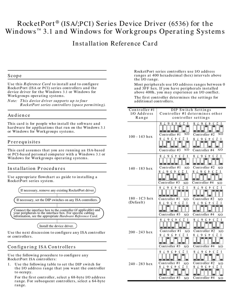
Comtrol
Comtrol RocketPort PCI Series Quick Installation Reference Card
SyxthSense
SyxthSense SYX66 Series Commissioning Guide

Samson
Samson EB 2111 TRANSLATION OF ORIGINAL INSTRUCTIONS
Galil Motion Control
Galil Motion Control DMC-14 5 Series manual
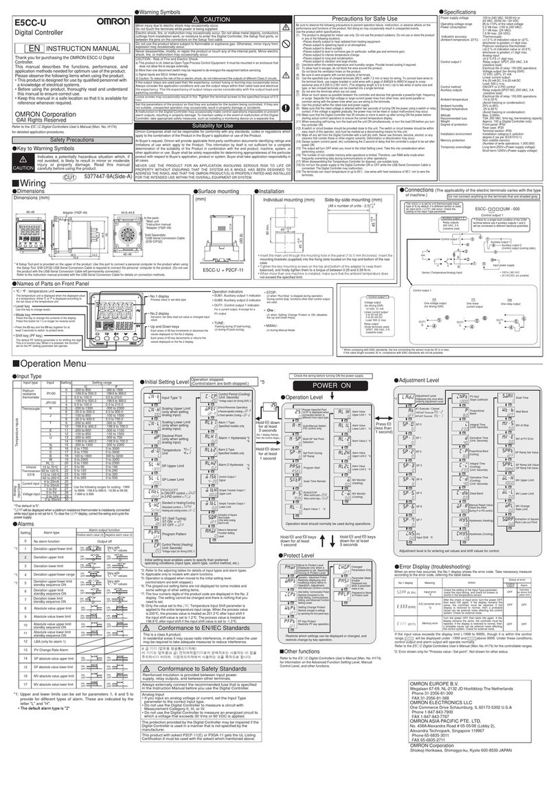
Omron
Omron E5CC-U instruction manual
