manuals.online logo
Brands
  1. Home
  2. •
  3. Brands
  4. •
  5. YOKOGAWA
  6. •
  7. Controllers
  8. •
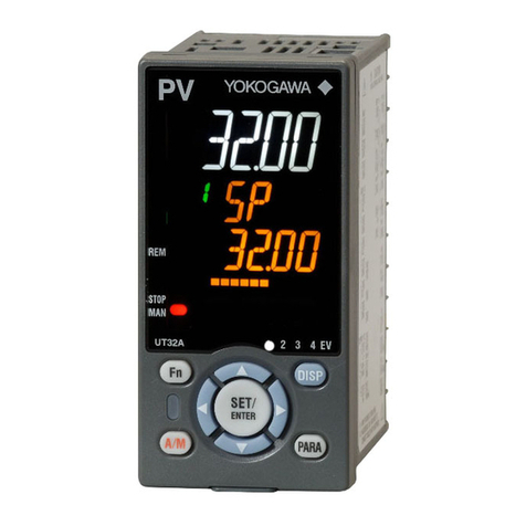
  9. YOKOGAWA UT35A/MDL User manual

YOKOGAWA UT35A/MDL User manual

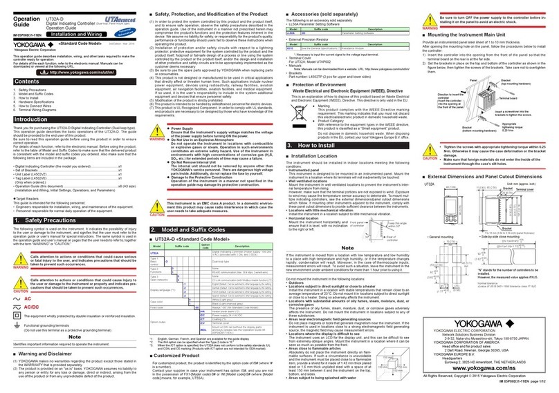
IM 05P01D81-11EN page 1/6
Contents
1. Safety Precautions
2. ModelandSu󰀩xCodes
3. How to Install
4. HardwareSpecications
5. HowtoConnectWires
6. TerminalWiringDiagrams
7. Setup Procedure
8. Operations
9. Troubleshooting
Introduction
ThankyouforpurchasingtheUT35A/MDL,UT32A/MDLController.(TheUT35Aand
UT32Awithoption/MDLhavenodisplay.)
Thisoperationguidedescribestheinstalling,wirings,setupow,andtroubleshooting
oftheUT35A/MDLandUT32A/MDL.Theguideshouldbeprovidedtotheenduser
of this product.
Besuretoreadthisoperationguidebeforeusingtheproductinordertoensure
correctoperation.Fordetailsofeachfunction,refertotheelectronicmanual.Before
usingtheproduct,refertothetableofModelandSu󰀩xCodestomakesurethatthe
deliveredproductisconsistentwiththemodelandsu󰀩xcodesyouordered.Also
makesurethatthefollowingitemsareincludedinthepackage.
•Controller(themodelyouordered) .........................................................x1
•UnitLabel(L4502VZ) ..............................................................................x1
•TagLabel(L4502VE) ..............................................................................x1
(Onlywhenordered.)
•OperationGuide(thisdocument) ............................................................x3(A3size)
(InstallationandWiring,InitialSettings,Operations,andParameters)
l
TargetReaders
Thisguideisintendedforthefollowingpersonnel;
• Engineersresponsibleforinstallation,wiring,andmaintenanceoftheequipment.
• Personnelresponsiblefornormaldailyoperationoftheequipment.
1. Safety Precautions
Thefollowingsymbolisusedon the instrument.Itindicatesthepossibility of injury
totheuserordamagetothe instrument, andsigniesthattheusermust refer tothe
operationguideoruser’smanualforspecialinstructions.Thesamesymbolisusedin
theoperationguideanduser’smanualonpagesthattheuserneedstoreferto,together
withtheterm“WARNING”or“CAUTION.”
WARNING
Calls attention to actions or conditions that could cause serious
or fatal injury to the user, and indicates precautions that should be
taken to prevent such occurrences.
CAUTION
Calls attention to actions or conditions that could cause injury to
the user or damage to the instrument or property and indicates pre-
cautions that should be taken to prevent such occurrences.
AC
AC/DC
Theequipmentwhollyprotectedbydoubleinsulationorreinforcedinsulation.
Functionalgroundingterminals
  (Donotusethisterminalasaprotectivegroundingterminal).
Note
Identiesimportantinformationrequiredtooperatetheinstrument.
■Warning and Disclaimer
(1) YOKOGAWA makesno warrantiesregardingthe productexceptthosestated in
theWARRANTYthatisprovidedseparately.
(2) Theproductisprovidedonan"asis"basis.YOKOGAWAassumesnoliabilityto
anypersonorentityforanylossordamage,directorindirect,arisingfromthe
use of the product or from any unpredictable defect of the product.
■ Safety,Protection,andModicationoftheProduct
(1)Inordertoprotectthe system controlledbythisproductandtheproductitself,
andtoensuresafeoperation,observethesafetyprecautionsdescribedinthe
operationguide.Useoftheinstrumentin a mannernotprescribedhereinmay
compromise the product's functions and the protection features inherent in the
device.Weassumenoliabilityforsafety,orresponsibilityfortheproduct'squality,
performanceorfunctionalityshouldusersfailtoobservetheseinstructionswhen
operatingtheproduct.
(2)Installationof protection and/or safetycircuitswithrespecttoalightning
protector;protectiveequipmentforthesystemcontrolledbytheproductandthe
productitself;foolprooforfail-safedesignofaprocessorlineusingthesystem
controlledbytheproductortheproductitself;and/orthedesignandinstallation
ofotherprotectiveandsafetycircuitsaretobeappropriatelyimplementedasthe
customer deems necessary.
(3) Be sureto usethe spare partsapproved byYOKOGAWAwhen replacingparts
or consumables.
(4) This productis notdesigned or manufacturedto be usedin criticalapplications
thatdirectlyaffectorthreatenhumanlives.Suchapplicationsincludenuclear
powerequipment,devicesusingradioactivity,railway facilities, aviation
equipment,airnavigationfacilities,aviationfacilities,andmedicalequipment.
Ifsoused,itistheuser’sresponsibilitytoincludeinthesystem additional
equipmentanddevicesthatensurepersonnelsafety.
(5) Modicationoftheproductisstrictlyprohibited.
(6)
Thisproductisintendedtobehandledbyskilled/trainedpersonnelforelectricdevices.
(7)ThisproductisULRecognizedComponent.InordertocomplywithULstandards,
end-productsarenecessarytobedesignedbythosewhohaveknowledgeofthe
requirements.
WARNING
l
Power Supply
Ensure that the instrument’s supply voltage matches the voltage
of the power supply before turning ON the power.
lDo Not Use in an Explosive Atmosphere
Do not operate the instrument in locations with combustible
or explosive gases or steam. Operation in such environments
constitutes an extreme safety hazard. Use of the instrument in
environments with high concentrations of corrosive gas (H2S,
SOX, etc.) for extended periods of time may cause a failure.
lDo Not Remove Internal Unit
The internal unit should not be removed by anyone other than
YOKOGAWA's service personnel. There are dangerous high voltage
parts inside. Additionally, do not replace the fuse by yourself.
lDamage to the Protective Construction
Operation of the instrument in a manner not specified in the
operation guide may damage its protective construction.
CAUTION
This instrument is an EMC class A product. In a domestic environ-
ment this product may cause radio interference in which case the
user needs to take adequate measures.
2. ModelandSu󰀩xCodes
■UT35A/MDL «Standard Code Model»
Model Su󰀩xcode Option
code Description
UT35A /MDL
(Required)
DigitalIndicatingController(Powersupply:100-240V
AC)(providedwithretransmissionoutputor15VDC
looppowersupply,2DIs,and3DOs)(*3)
Type1:
Basic
control
-0 Standard type
-2 Heating/coolingtype
Type2:
Functions
0None
25additionalDIs,5additionalDOs
Type3:Open
networks
0None
1
RS-485communication(Max.38.4kbps,2-wire/4-wire)
2Ethernetcommunication(withserialgatewayfunction)
3
CC-Linkcommunication(withModbusmasterfunction)
4
PROFIBUS-DPcommunication(withModbusmasterfunction)
5
DeviceNetcommunication(withModbusmasterfunction)
Fixedcode -1
Temperatureunit:degC&degF
Casecolor 1Black(Lightcharcoalgray)
Fixedcode -00 Always"-00"(forStandardCodeModel)
Option codes
/MDL
(Required)
MountonDINrail(withoutthedisplaypartsandkeys)
(*1)
/LP 24VDClooppowersupply(*1)
/DC Powersupply24VAC/DC
/CT Coating(*2)
/CV Terminalcover
*1: When/MDLoptionand/LPoptioniscombined,only“0”canbespecifiedforType2code.
*2: Whenthe/CToptionisspecified,theUT35Adoesnotconformtothesafetystandards(UL
andCSA)andCEmarking(Productswith/CToptionarenotintendedforEEA-market).
*3: UT35Ahasapanelmounttype(withoutoption/MDL).PleaseseetheOperationGuide(IM
05P01D31-11EN).
■UT32A/MDL «Standard Code Model»
Model Su󰀩xcode Option
code Description
UT32A /MDL
(Required)
DigitalIndicatingController(Powersupply:100-240
VAC)(providedwithretransmissionoutputor15V
DClooppowersupply,2DIs,and3DOs)(*6)
Type1:
Basic
control (*7)
-0 Standard type
-2 Heating/coolingtype
Type2:
Functions
0None
1
RS-485communication(Max.38.4kbps,2-wire/4-wire)(*1)
Type3:
Open networks
0None
3
CC-Linkcommunication(withModbusmasterfunction)
Fixedcode -1
Temperatureunit:degC&degF
Casecolor 1Black(Lightcharcoalgray)
Fixedcode -00 Always"-00"(forStandardCodeModel)
Option codes
/MDL
(Required)
MountonDINrail(withoutthedisplaypartsandkeys)
(*2)(*3)
/LP 24VDClooppowersupply(*3)
/HA Heaterbreakalarm(*4)
/DC Powersupply24VAC/DC
/CT Coating(*5)
/CV Terminalcover
*1:
When/LPoptionisspecified,theRS-485communicationofthetype2code“1”is2-wiresystem.
*2:
The/MDLoptionisspecified,themodelandsuffixcodesarefollows:
 UT32A-010-11-00/x/MDL
 UT32A-003-11-00/x/MDL
 UT32A-210-11-00/x/MDL
*3: When/MDLoptionand/LPoptioniscombined,“3”cannotbespecifiedforType3code.
*4:
The/HAoptioncanbespecifiedonlyinthecombinationofType2code“1”andType3code“0.”
*5: Whenthe/CToptionisspecified,theUT32Adoesnotconformtothesafetystandards(UL
andCSA)andCEmarking(Productswith/CToptionarenotintendedforEEA-market).
*6: UT32Ahasapanelmounttype(withoutoption/MDL).PleaseseetheOperationGuide(IM
05P01D31-11EN).
*7: UT32AhasalsoaDual-looptypemodel;forinformation,seeManualsinSection-6.
■CustomizedProduct
 Forcustomizedproduct,theproductisidentiedbytheoptioncodeof/S#(where‘#’
isanumber).
 Contactyoursupplierincase your instrumenthasoption/S#,andyou are not
inthepossessionofFX1-[Modelcode]-S#orIM[Model code]-S# (where[Model
code]means,forexample,UT55A).
■Accessories (sold separately)
Thefollowingisanaccessorysoldseparately.
• LL50AParameterSettingSoftware
Model Su󰀩xcode Description
LL50A -00 ParameterSettingSoftware
• ExternalPrecisionResistor
Model Su󰀩xcode Description
X010 SeetheGeneralSpecications(*) ResistanceModule
 *:Necessarytoinputthecurrentsignaltothevoltageinputterminal.
• TerminalCover
 ForUT35A:ModelUTAP001;ForUT32A:ModelUTAP002
• Manuals
 Note:Manualscanbedownloadedfromawebsite.URL:http://www.yokogawa.com/ns/ut/im/
• Brackets
 Partnumber:L4502TP(2pcsforupperandlowersides)
• Wallmountbracket
 ForUT32A/MDL:ModelUTAP005
3. How to Install
■Installation Location
Theinstrumentshouldbeinstalledinindoorlocations meeting thefollowing
conditions:
• Instrumented enclosure
 Thisinstrumentisdesignedtobemountedinaninstrumented enclosure. Mount
theinstrumentinalocationwhereitsterminalswillnotinadvertentlybetouched.
Be sure to mount the instrument in an enclosure with a door.
• Well ventilated locations
 Mounttheinstrumentinwellventilatedlocationstopreventtheinstrument’sinter-
naltemperaturefromrising.
 However,makesurethattheterminalportionsarenotexposedtowind.Exposure
to wind may cause the temperature sensor accuracy to deteriorate. To mount mul-
tipleindicatingcontrollers,seetheexternaldimensions which follow.Ifmounting
otherinstrumentsadjacenttothe instrument, complywiththeseexternaldimen-
sionstoprovidesu󰀩cientclearancebetweentheinstruments.
• Locations with little mechanical vibration
 Installtheinstrumentinalocationsubjecttolittlemechanicalvibration.
• Horizontal location
 Mounttheinstrumenthorizontallyandensurethatitislevel,withnoinclinationto
therightorleft.
Note
Iftheinstrumentismovedfromalocationwithlowtemperatureandlowhumidity
toaplacewithhightemperatureandhighhumidity,orifthe temperature changes
rapidly,condensationwillresult.Moreover,inthecaseofthermocoupleinputs,
measurementerrorswillresult.Toavoidsuchasituation,leavetheinstrumentinthe
newenvironmentunderambientconditionsformorethan1hourpriortousingit.
Donotmounttheinstrumentinthefollowinglocations:
• Outdoors
• Locations subject to direct sunlight or close to a heater
Install the instrument in a location with stable temperatures that remain close to an
averagetemperatureof23°C.Donotmountitinlocationssubjecttodirectsunlight
orclosetoaheater.Doingsoadverselya󰀨ectstheinstrument.
• Locations with substantial amounts of oily fumes, steam, moisture, dust, or
corrosive gases
 Thepresenceofoilyfumes,steam, moisture,dust,orcorrosivegasesadversely
a󰀨ectstheinstrument.Donotmounttheinstrumentinlocationssubjecttoanyof
these substances.
• Areasnearelectromagneticeldgeneratingsources
 Donotplacemagnetsortoolsthatgeneratemagnetismneartheinstrument.Ifthe
instrumentisusedinlocationsclosetoastrongelectromagneticeldgenerating
source,themagneticeldmaycausemeasurementerrors.
• Areasclosetoammablearticles
 Absolutelydonotplacetheinstrumentdirectlyonam-
mablesurfaces.Ifsuchacircumstanceisunavoidable
andtheinstrumentmustbeplacedclosetoaammable
item,provideashieldforitmadeof1.43mmthickplated
steel or 1.6 mm thick unplated steel with a space of at
least150mmbetweenitandtheinstrumentonthetop,
bottom,andsides.
• Areas subject to being splashed with water
WARNING
Be sure to turn OFF the power supply to the controller before in-
stalling it on the enclosure to avoid an electric shock.
150 mm150 mm
150 mm
150 mm
Operation
Guide
IM 05P01D81-11EN
UT35A/MDL, UT32A/MDL
Digital Indicating Controller (DIN Rail Mounting Type)
Operation Guide
This operation guide describes installation, wiring, and other tasks required to make the
controller ready for operation.
4th Edition: Mar. 2018
For details of the each function, refer to the electronic manual. Manuals can be
downloaded or viewed at the following URL.
Functional
Enhancement
http://www.yokogawa.com/ns/ut/im/
«Standard Code Model»
www.yokogawa.com/ns
YOKOGAWA ELECTRIC CORPORATION
Network Solutions Business Division
2-9-32, Naka-cho Musashino-shi, Tokyo 180-8750 JAPAN
YOKOGAWA CORPORATION OF AMERICA
Head office and for product sales
2 Dart Road, Newnan, Georgia 30265, USA
YOKOGAWA EUROPE B.V.
Headquarters
Euroweg 2, 3825 HD Amersfoort, THE NETHERLANDS
All Rights Reserved, Copyright © 2015 Yokogawa Electric Corporation
■Protection of Environment
Waste Electrical and Electronic Equipment (WEEE), Directive
ThisisanexplanationofhowtodisposeofthisproductbasedonWasteElectrical
andElectronicEquipment(WEEE),Directive.ThisdirectiveisonlyvalidintheEU.
● Marking
ThisproductcomplieswiththeWEEEDirectivemarking
requirement.Thismarkingindicatesthatyoumustnotdiscard
thiselectrical/electronicproductindomestichouseholdwaste.
● ProductCategory
WithreferencetotheequipmenttypesintheWEEEdirective,
thisproductisclassiedasa“Smallequipment”product.
Donot disposein domestichousehold waste. When disposing
products in the EU, contact your localYokogawa Europe B.V.
o󰀩ce.
IM 05P01D81-11EN page 2/6
■Mounting on a DIN Rail
InserttheDINrailintothetopareaofDINrailgroove(attwolocations)ontherear
panel,andsecureinplacewiththebottomslidelock.
DIN rail
DIN rail
Slide lock
UT35A/MDL: 2, UT32A/MDL: 1
Fit into here
Push
4. HardwareSpecications
WARNING
This instrument is for Measurement Category No.1.
Do not use it for measurements in locations falling under Measure-
ment Categories No.2, No.3, and No.4.
Internal Wiring
Outlet
Entrance
IV
Cable
III T
O( I )
II
Category IEC/EN/CSA/UL
61010-1 EN 61010-2-030 Remarks
No.1 Measurement
CategoryI O(Other) For measurements performed on circuits not direct-
lyconnectedtoMAINS.
No.2 Measurement
CategoryII
Measurement
CategoryII
For measurements performed on circuits directly
connectedtothelow-voltageinstallation.
No.3 Measurement
CategoryIII
Measurement
CategoryIII
Formeasurementsperformedinthebuildinginstal-
lation.
No.4 Measurement
CategoryIV
Measurement
CategoryIV
For measurements performed at the source of the
low-voltageinstallation.
■ InputSpecications
●UniversalInput(Equippedasstandard)
• Numberofinputs:1
• Inputtype,instrumentrange,andmeasurementaccuracy:Seethetablebelow,
Input Type Instrument Range Accuracy
ºC ºF
Thermo-
couple
K
-270.0to1370.0ºC -450.0to2500.0ºF ±0.1%ofinstrumentrange±1digitfor
0°Cormore
±0.2%ofinstrumentrange±1digitfor
lessthan0°C
±2%ofinstrumentrange±1digitfor
lessthan-200.0°CofthermocoupleK
±1%ofinstrumentrange±1digitfor
lessthan-200.0°CofthermocoupleT
-270.0to1000.0ºC -450.0to2300.0ºF
-200.0to500.0ºC -200.0to1000.0ºF
J-200.0to1200.0ºC -300.0to2300.0ºF
T
-270.0to400.0ºC -450.0to750.0ºF
0.0to400.0ºC -200.0to750.0ºF
B0.0to1800.0ºC 32to3300ºF
±0.15%ofinstrumentrange±1digit
for400°Cormore
±5%ofinstrumentrange±1digitfor
lessthan400°C
S0.0to1700.0ºC 32to3100ºF ±0.15%ofinstrumentrange±1digit
R 0.0to1700.0ºC 32to3100ºF
N -200.0to1300.0ºC -300.0to2400.0ºF
±0.1%ofinstrumentrange±1digit
±0.25%ofinstrumentrange±1digit
forlessthan0°C
E -270.0to1000.0ºC -450.0to1800.0ºF ±0.1%ofinstrumentrange±1digitfor
0°Cormore
±0.2%ofinstrumentrange±1digitfor
lessthan0°C
±1.5%ofinstrumentrange±1digitfor
lessthan-200.0°CofthermocoupleE.
L -200.0to900.0ºC -300.0to1600.0ºF
U
-200.0to400.0ºC -300.0to750.0ºF
0.0to400.0ºC -200.0to1000.0ºF
W 0.0to2300.0ºC 32to4200ºF ±0.2%ofinstrumentrange±1digit
(Note2)
Platinel 2 0.0to1390.0ºC 32.0to2500.0ºF ±0.1%ofinstrumentrange±1digit
PR20-40 0.0to1900.0ºC 32to3400ºF
±0.5%ofinstrumentrange±1digitfor
800°Cormore
Accuracyisnotguaranteedforless
than800°C.
W97Re3-
W75Re25 0.0to2000.0ºC 32to3600ºF ±0.2%ofinstrumentrange±1digit
RTD
JPt100 -200.0to500.0ºC -300.0to1000.0ºF ±0.1%ofinstrumentrange±1digit
(Note1)
-150.00to150.00ºC -200.0to300.0ºF ±0.1%ofinstrumentrange±1digit
Pt100
-200.0to850.0ºC -300.0to1560.0ºF ±0.1%ofinstrumentrange±1digit
(Note1)
-200.0to500.0ºC -300.0to1000.0ºF
-150.00to150.00ºC -200.0to300.0ºF ±0.1%ofinstrumentrange±1digit
Standardsignal
0.400to2.000V
±0.1%ofinstrumentrange±1digit
1.000to5.000V
4.00to20.00mA
DCvoltage/current
0.000to2.000V
0.00to10.00V
0.00to20.00mA
-10.00to20.00mV
0.0to100.0mV
Theaccuracyisthatinthestandardoperatingconditions:23±2°C,55±10%RH,andpower
frequencyat50/60Hz.
Note1: ±0.3°C±1digitintherangebetween0and100°C,±0.5°C±1digitintherange
 between-100and200°C.
Note2: W:W-5%Re/W-26%Re(HoskinsMfg.Co.).ASTME988
•Inputsampling(control)period:200ms
•Burnoutdetection:
  FunctionsatTC,RTD,andstandardsignal.
  Upscale,downscale,ando󰀨canbespecied.
  Forstandardsignal,burnoutisdeterminedtohaveoccurredifitis0.1Vor0.4
 mAorless.
•Inputbiascurrent:0.05µA(forTCorRTD)
•Measuredcurrent(RTD):About0.16mA
•Inputresistance:
  TCormVinput:1MΩormore
  Vinput:About1MΩ
  mAinput:About250Ω
•Allowablesignalsourceresistance:
  TCormVinput:250Ωorless
  E󰀨ectsofsignalsourceresistance:0.1µV/Ωorless
  DCvoltageinput:2kΩorless
  E󰀨ectsofsignalsourceresistance:About0.01%/100Ω
• Allowablewiringresistance:
  RTDinput:Max.150Ω/wire(Theconductorresistancebetweenthethreewires
 shallbeequal.)
  Wiringresistancee󰀨ect:±0.1ºC/10Ω
• Allowableinputvoltage/current:
  TC,mV,mAandRTDinput:±10VDC
  Vinput:±20VDC
  mAinput:±40mA
• Noiserejectionratio:
  Normalmode:40dBormore(at50/60Hz)
  Commonmode:120dBormore(at50/60Hz)
  For100-240VAC,thepowerfrequencycan be setmanually.Automatic
 detectionisalsoavailable.
  For24VAC/DC,thepowerfrequencycanbesetmanually.
• Referencejunctioncompensationerror:
  ±1.0ºC(15to35ºC),±1.5ºC(-10to15ºCand35to50ºC)
• Applicablestandards:JIS/IEC/DIN(ITS-90)forTCandRTD
■ ContactInputSpecications
• Numberofinputs:SeethetableofModelandSu󰀩xCodes.
• Inputtype:No-voltagecontactinputortransistorcontactinput
• Inputcontactrating:12VDC,10mAormore
  Useacontactwithaminimumon-currentof1mAorless.
• ON/OFFdetection:
  No-voltagecontactinput:
  Contactresistanceof1kΩorlessisdeterminedas“ON”andcontact
  resistanceof50kΩormoreas“OFF.”
  Transistorcontactinput:
  Inputvoltageof2Vorlessisdeterminedas“ON”andleakagecurrentmust
  notexceed100µAwhen“OFF.”
• Minimumstatusdetectionholdtime:Controlperiod+50ms
• Use:SPswitch,operationmodeswitch,andeventinput
■ AnalogOutputSpecications
• Numberofoutputs:
  Controloutput:1
  Cooling-sidecontroloutputofHeating/coolingtype(Retransmissionoutput
 terminal):1
• Outputtype:Currentoutputorvoltagepulseoutput
• Currentoutput:4to20mADCor0to20mADC/loadresistanceof600Ωorless
• Currentoutputaccuracy:±0.1%ofspan(±5%ofspanfor1mAorless)
  Theaccuracyis that in thestandardoperatingconditions:23±2°C,55±10%RH,
 andpowerfrequencyat50/60Hz.
• Voltagepulseoutput:
  Use:Timeproportionaloutput
  On-voltage:12Vormore/loadresistanceof600Ωormore
  O󰀨-voltage:0.1VDCorless
  Timeresolution:10msor0.1%ofoutput,whicheverislarger
■ RetransmissionOutputSpecications
• Numberofoutputs:Retransmissionoutput;1,shared with 15VDClooppower
supplyorCooling-sidecontroloutput.
• Currentoutput:4to20mADCor0to20mADC/loadresistanceof600Ωorless
• Currentoutputaccuracy(conversionaccuracy from PVdisplayonthesetscale):
±0.1%ofspan(±5%ofspanfor1mAorless)
 Theaccuracyisthatinthestandardoperatingconditions:23±2°C,55±10%RH,
 andpowerfrequencyat50/60Hz.
 Thisisnotconversionaccuracythroughinput and outputbuttheperformanceof
transmission output itself.
■ 15VDCLoopPowerSupplySpecications
(SharedwithretransmissionoutputorCooling-sidecontroloutput.)
• Powersupply:14.5to18.0VDC
• Maximumsupplycurrent:About21mA(withshort-circuitcurrentlimitingcircuit)
■ StepResponseTimeSpecications
Within1s(63%ofanalogoutputresponsetimewhenastepchangeof10to90%of
inputspanisapplied)
■External Dimensions
●UT35A/MDL
37(1.46)
96(3.78)
20(0.79)
100(3.94)
Note:
Trigonometry
General tolerance = ±(JIS B 0401-1998 tolerance class IT18)/2
Unit: mm(inch)
60(2.36)
DIN rail
TH35-75A
Cable for LL50
Minimum cable curvature: R40 (1.57)
4.3(0.17)
4(0.16)
90 (3.54) min.
(required for removing the
instrument from the DIN rail)
120 (4.72) min.
(required for inserting/removing the cable for LL50A)
91.6(3.61)
114(4.49)
100(3.94)
94.6(3.72)
●UT32A/MDL
15(0.59)
48.2(1.90)
20(0.79)
100(3.94)
Unit: mm(inch)
60(2.36)
DIN rail
TH35-75A
Cable for LL50
4.3(0.17)
4(0.16)
91.6(3.61)
114(4.49)
100(3.94)
94.6(3.72)
Note:
Trigonometry
General tolerance = ±(JIS B 0401-1998 tolerance class IT18)/2
Minimum cable curvature: R40 (1.57)
90 (3.54) min.
(required for removing the
instrument from the DIN rail)
120 (4.72) min.
(required for inserting/removing the cable for LL50A)
CAUTION
Make sure that foreign materials do not enter the inside of the in-
strument through the case’s slit holes.
■Removing from the DIN Rail
Insertaat-bladescrewdriver(guideline: 100 mmshaftlength,6mmbladewidth,
0.8mmbladethickness)intothebottomslidelockholeandpulldowntoreleasethe
slidelock.OntheUT55A/MDL,therearetwoslidelocks.Releasetheotherslide
lockafteryoureleasetherstslidelock.When both slidelocksareunlocked,the
instrumentcanberemovedfromtheDINrail.
DIN rail
Slide lock
UT35A/MDL: 2, UT32A/MDL: 1
Pull
Push up
DIN rail
IM 05P01D81-11EN page 3/6
■ RelayContactOutputSpecications
• Contacttypeandnumberofoutputs:
  Controloutput:contactpoint1c;1point
  Heating/coolingtype:contactpoint1a;2pointsforbothheatingandcoolingsides
  Alarmoutput:contactpoint1a;3points(commonisindependent)
• Contactrating:
  Contactpoint1c(controloutput):250VAC,3Aor30VDC,3A(resistanceload)
  Contactpoint1a(controloutput):240VAC,3Aor30VDC,3A(resistanceload)
  Contactpoint1a(alarmoutput):240VAC,1Aor30VDC,1A(resistanceload)
• Use:Timeproportionaloutput,alarmoutput,FAILoutput,etc.
• Timeresolutionofcontroloutput:10msor0.1%ofoutput,whicheverislarger
Note:Thecontroloutputshouldalwaysbeusedwithaloadof10mAormore.
 Thealarmoutputshouldalwaysbeusedwithaloadof1mAormore.
■ TransistorContactOutputSpecications
• Numberofoutputs:SeethetableofModelandSu󰀩xCodes.
• Outputtype:Opencollector(SINKcurrent)
• Outputcontactrating:Max.24VDC,50mA
• Outputtimeresolution:Min.200ms
• Use:Alarmoutput,FAILoutput,etc.
■ HeaterBreakAlarmSpecications
• Numberofinputs:2
• Numberofoutputs:2(transistorcontactoutput)
• Use:Measurestheheatercurrentusinganexternalcurrenttransformer(CT)and
generatesaheaterbreakalarmwhenthemeasured value islessthanthebreak
detectionvalue.
• Currenttransformerinputresistance:About9.4Ω
•
Currenttransformerinputrange:0.0to0.1Arms(0.12Armsormorecannotbeapplied.)
• Heatercurrentsettingrange:OFF,0.1to300.0Arms
  Heatercurrentmeasuredvaluedisplayrange:0.0to360.0Arms
 Note:TheCTratiocanbeset.CTratiosettingrange:1to3300
• RecommendedCT:CTfromU.R.D.,Ltd.
  CTL-6-S-H:CTratio800,measurablecurrentrange:0.1to80.0Arms
  CTL-12L-30:CTratio3000,measurablecurrentrange:0.1to180.0Arms
• Heatercurrentmeasurementperiod:200ms
• Heatercurrentmeasurementaccuracy:±5%ofcurrent transformer inputrange
span±1digit(CTerrorisnotincluded.)
•
Heatercurrentdetectionresolution:Within1/250ofcurrenttransformerinputrangespan
• BreakdetectionOn-time:Min.0.2second(fortimeproportionaloutput)
■ 24VDCLoopPowerSupplySpecications
• Use:Powerissuppliedtoa2-wiretransmitter.
• Powersupply:21.6to28.0VDC
• Ratedcurrent:4to20mADC
• Maximumsupplycurrent:About30mA(withshort-circuitcurrentlimitingcircuit.)
■ MaintenacePortSpecications
Themaintenanceportis usedtoconnectadedicatedcablewhenusingtheLL50A
ParameterSettingSoftware(soldseparately). Throughthisport,youcanset
controllerparameters,downloadladderprograms,andsoon.
Fordetails,seetheLL50AUser’sManual(IM05P05A01-02EN).
Dedicated cable
LL50A Parameter Setting Software
To USB terminal
Note
UseLL50Awiththecontrollerturnedon.(Thededicatedcablemustbeconnected.
LL50ALight-loaderadaptercannotbeused.)
ThemaintenanceportisnotisolatedfromthePVinputterminal.Usetheportonlyfor
maintenancepurposes,suchasforsettingthecontrollerparameters.
■ SafetyandEMCStandards
• Safety:
 CompliantwithIEC/EN61010-1(CE),IEC/EN61010-2-201(CE),IEC/EN61010-
2-030(CE),approvedbyCAN/CSAC22.2No.61010-1(CSA),approvedbyUL
61010-1.
 Installationcategory:II
 Pollutiondegree:2
 Measurementcategory:I(CATI)(UL,CSA)
O(Other)(CE)
 Ratedmeasurementinputvoltage:Max.10VDC
 Ratedtransientovervoltage:1500V(*)
 *ThisisareferencesafetystandardvalueformeasurementcategoryIofCSA/UL61010-
1,andformeasurementcategoryOofIEC/EN61010-2-030.Thisvalueisnotnecessarilya
guaranteeofinstrumentperformance.
• EMCstandards:
 CompliantwithCEmarking
 EN61326-1ClassA,Table2(Foruseinindustriallocations),
 EN61326-2-3
 *Theinstrumentcontinuestooperateatameasurementaccuracyofwithin±20%ofthe
rangeduringtesting.
 EN55011ClassA,Group1
 EN61000-3-2ClassA
 EN61000-3-3
 EMCRegulatoryArrangementinAustraliaandNewZealand(forallmodelinclud-
ingLL50A)
 EN55011ClassA,Group1
• KCmarking:
 Electromagneticwaveinterferencepreventionstandard,electromagnetic wave
protection standard compliance
■ Construction,Installation,andWiring
• Construction:DINrailmountingtype
• Material:Polycarbonate(Flameretardancy:UL94V-0)
 DINrailmountingbracketmaterial:Panelsteelsheet
• Casecolor:Black(Lightcharcoalgray)
• Weight:1kgorless
• Externaldimensions(mm):
 UT35A/MDL:96(width)x114(height)x100(depth)
 UT32A/MDL:48.2(width)x114(height)x100(depth)
• CompatibleDINrails:TH35-7.5Fe,TH35-7.5Aℓ,JISC2812
•
Mountingposition:Horizontal.
• Wiring:M3screwterminalwithsquarewasher(forsignalwiringandpowerwiring)
■ PowerSupplySpecicationsandIsolation
• Powersupply:
  Ratedvoltage:100-240VAC(+10%/-15%),50/60Hz
       24VAC/DC(+10%/-15%)(for/DCoption)
• Powerconsumption:UT35A:18VA(DC:9VA,AC:14VAif/DCoptionisspecied)
   UT32A:15VA(DC:7VA,AC:11VAif/DCoptionisspecied)
• Databackup:Nonvolatilememory
• Powerholduptime:20ms(for100VACdrive)
• Withstandingvoltage
Betweenprimaryterminalsandsecondaryterminals:2300VACfor1minute(UL,CSA)
 Betweenprimaryterminalsandsecondaryterminals:3000VACfor1minute(CE)
  Betweenprimaryterminals:1500VACfor1minute
  Betweensecondaryterminals:500VACfor1minute
   (Primary terminals:Power*andrelayoutputterminals;Secondaryterminals:
  AnalogI/Osignalterminals,contactinputterminals,communicationterminals
  andfunctionalgroundingterminals.)
 *:Powerterminalsfor24VAC/DCmodelsarethesecondaryterminals.
• Insulationresistance:Betweenpowersupplyterminalsandagroundingterminal
20MΩormoreat500VDC
• Isolationspecications
PV (universal ) input terminals / remote input terminals
Control relay (contact point c/contact point a x 2) output terminals
Alarm-1 relay (contact point a) output terminals
Alarm-2 relay (contact point a) output terminals
Alarm-3 relay (contact point a) output terminals
Contact input terminals (all)
RS-485 communication terminals
24 V DC loop power supply terminals
Contact output (transistor) terminals
Ethernet communication terminal
PROFIBUS-DP/DeviceNet/CC-Link communication terminals
Current transformer input terminals
Control, retransmission (analog) output terminals
(not isolated between the analog output terminals)
Internal
circuits
Power
supply
The circuits divided by lines are insulated mutually.
■ EnvironmentalConditions
Normal Operating Conditions:
• Ambienttemperature:-10to50°C
IftheCC-Linkoptionisspecied,0to50°CforUT35A/MDL;0to40°CforUT32A/
MDL.(side-by-sidemounting:0to50°CforUT55A/MDL;0to40°CforUT52A/MDL)
• Ambienthumidity:20to90%RH(nocondensationallowed)
• Magneticeld:400A/morless
• Continuousvibrationat5to9Hz:Halfamplitudeof1.5mmorless,1oct/minfor90
minuteseachinthethreeaxisdirections
 Continuousvibrationat9to150Hz:4.9m/s2orless,1oct/minfor90minuteseach
inthethreeaxisdirections
• Short-periodvibration:14.7m/s2,15secondsorless
• Shock:98m/s2orless,11ms
• Altitude:2000morlessabovesealevel
• Warm-uptime:30minutesormoreafterthepoweristurnedon
• Startuptime:Within10seconds
 *: TheLCD(aliquidcrystaldisplay)isusedforadisplayportionofthisproduct.
 TheLCDhasacharacteristicthatthedisplayactionbecomeslateatthelow
 temperature.However,thecontrolfunctionisnotaffected.
Transportation and Storage Conditions:
• Temperature:-25to70ºC
• Temperaturechangerate:20ºC/horless
• Humidity:5to95%RH(nocondensationallowed)
E󰀨ectsofOperatingConditions
• E󰀨ectofambienttemperature:
  VoltageorTCinput:±1µV/ºCor±0.01%ofF.S./ºC,whicheverislarger
  Currentinput:±0.01%ofF.S./ºC
  RTDinput:±0.05ºC/ºC(ambienttemperature)orless
  Analogoutput:±0.02%ofF.S./ºCorless
• E󰀨ectofpowersupplyvoltageuctuation
  Analoginput:±0.05%ofF.S.orless
  Analogoutput:±0.05%ofF.S.orless
  (Eachwithinratedvoltagerange)
5. How to Connect Wires
WARNING
• Wiring work must be carried out by a person with basic electrical
knowledge and practical experience.
• Be sure to turn OFF the power supply to the controller before
wiring to avoid an electric shock. Use a tester or similar device
to ensure that no power is being supplied to a cable to be
connected.
• For the wiring cable, the temperature rating is 75 °C or more.
• As a safety measure, always install a circuit breaker (an IEC
60947-compatible product, 5 A, 100 V or 220 V AC) in an easily
accessible location near the instrument. Moreover, provide
indication that the switch is a device for turning off the power to
the instrument.
• Install the power cable keeping a distance of more than 1 cm
from other signal wires.
•
The power cable is required to meet the IEC standards concerned or
the requirements of the area in which the instrument is being installed.
• Wiring should be installed to conform to NEC (National Electrical
Code: ANSI/NFPA-70) or the wiring construction standards in
countries or regions where wiring will be installed.
• Since the insulation provided to each relay output terminal is
Functional insulation, provide Reinforced insulation to the
external of the device as necessary. (Refer to the drawing below.)
This product
Functional
insulation
A safety
voltage circuit
A safety
voltage circuit
This product
Reinforced insulation
Functional
insulation
A hazardous
voltage circuit
A hazardous
voltage circuit
A safety
voltage circuit
A safety
voltage circuit
This product
Reinforced insulation
Functional
insulation
A hazardous
voltage circuit
A hazardous
voltage circuit
A hazardous
voltage circuit
A hazardous
voltage circuit
CAUTION
• When connecting two or more crimp-on terminal lugs to the
single terminal block, bend the crimp-on terminal lugs before
tightening the screw.
• Note that the wiring of two or more crimp-on terminal lugs to the
single high-voltage terminal of the power supply and relay, etc.
does not comply with the safety standard.
CAUTION
• Provide electricity from a single-phase power supply. If the
power is noisy, install an isolation transformer on the primary
side, and use a line filter on the secondary side. When measures
against noise are taken, do not install the primary and secondary
power cables close to each other.
• If there is a risk of external lightning surges, use a lightning
arrester etc.
• For TC input, use shielded compensating lead wires for wiring.
For RTD input, use shielded wires that have low conductor
resistance and cause no significant differences in resistance
between the three wires.
• Since the control output relay has a life span (resistance load of
100,000 times), use the auxiliary relay to perform ON/OFF control.
• The use of inductance (L) loads such as auxiliary relays, motors
and solenoid valves causes malfunction or relay failure; always
insert a CR filter for use with alternating current or a diode for
use with direct current, as a spark-removal surge suppression
circuit, into the line in parallel with the load.
• After completing the wiring, the terminal cover is recommended
to use for the instrument.
● RecommendedCrimp-onTerminalLugs
(A)
(F)
(ød)
5.5
3.3
 Recommendedtighteningtorque:0.6N·m
 Applicablewiresize:Powersupplywiring1.25mm2or more
Applicable terminal lug Applicable wire size mm2(AWG#) (φd) (A) (F)
M3 0.25to1.65(22to16) 3.3 5.5 4.2
● CableSpecicationsandRecommendedCables
Purpose Name and Manufacturer
Powersupply,relaycontactoutputs 600VGradeheat-resistantPVCinsulatedwires,JISC
3317(HIV),0.9to2.0mm2
Thermocouple Shieldedcompensatingleadwires,JISC1610
Forthermocoupleinput(PVinputandremoteinputwithdirect
input),shieldedcompensatingleadwireofcross-sectionalarea
lessthanorequalto0.75mm2isrecommended.Ifthecross-
sectionalareaiswide,thereferencejunctioncompensation
errormaybelarge.
RTD Shieldedwires(three/fourconductors),UL2482(HitachiCable)
Othersignals(otherthancontactinput/output)
Shielded wires
Othersignals(contactinput/output)
Unshieldedwires
RS-485communication
Shielded wires
Ethernetcommunication
100BASE-TX(CAT-5)/10BASE-T
PROFIBUS-DPcommunication
DedicatedcableforPROFIBUS-DP(Shieldedtwo-wires)
DeviceNetcommunication
DedicatedcableforDeviceNet(Shieldedve-wires)
CC-Linkcommunication
DedicatedcableforCC-Link(Shieldedthree-wires)
PROFIBUS-DP/CC-LinkConnector(wiringside)(Partnumber:A1987JT)
DeviceNetConnector(wiringside)(Partnumber:L4502BW)
Recommendedtighteningtorque:0.5to0.6N·m
DC Relay Wiring
R
External DC power supply
Relay
UT35A, UT32A
UT’s contact
Diode
(Mount it directly
to the relay coil
terminal (socket).)
Relay
(Use one with a relay coil rating
less than the UT’s contact rating.)
AC Relay Wiring
UT35A, UT32A
R
UT’s contact
CR filter
(Mount it directly
to the relay coil
terminal (socket).)
External AC power supply
Relay
(Use one with a relay coil
rating less than the UT’s
contact rating.)
Transistor Output Wiring
power
+ –
UT
DO
Load
COM
IM 05P01D81-11EN page 4/6
6. Terminal Wiring Diagrams
CAUTION
• Do not use an unassigned terminal as the relay terminal.
Do not use a 100-240 V AC power supply for the 24 V AC/DC
model; otherwise, the instrument will malfunction.
■ UT35A/MDL
E4-terminal area
E3-terminal area
PV
E1-terminal area
PV input
TC input RTD input
Voltage (mV, V) input
A
+
-
+
-
Current (mA) input
+
-
B
b
(Suffix code: Type 1=-2)
(24 V AC/DC power supply: Option code /DC)
(Equipped
as standard)
Power supply
101
102
103
104
105
106
107
108
109
110
111
501
502
503
504
505
506
507
508
509
510
511
512
407
408
409
410
411
412
301
302
303
304
305
306
201
202
203
204
205
206
207
208
210
211
212
Cooling-side control output
101
-112
501
-512
401
-412
301
-306
201
-212
ALM
(Equipped
as standard)
Contact output
External contact output (relay)
AL3
AL2
AL1
Relay contact rating: 240 V AC, 1 A
30 V DC, 1 A (resistance load)
Alarm-3 output
(PV high limit)
Alarm-2 output
( PV low limit)
Alarm-1 output
(PV high limit)
Common
Common
Common
UT
104
105
106
107
108
109
100-240 V AC power supply
N
L
Allowable range:
100-240 V AC (+10%/-15%)
(free voltage)
50/60 Hz shared
110
111
24 V AC/DC power supply
-
+
110
111
202
203
201
202
203
202
203
203
204
RET/OUT2
Current/voltage pulse output
0-20 mA DC,
4-20 mA DC,
Voltage pulse (12V)
+
-
205
206
Factory default: PV input
type is undefined.
OUT
(Suffix code: Type1=-0)
Control output
101
102
Relay contact output
103
NC
NO
COM
Contact rating: 250 V AC, 3 A
30 V DC, 3 A (resistance load)
Factory default: Control output is relay.
OUT
Current/voltage pulse output
0-20 mA DC,
4-20 mA DC,
Voltage pulse (12 V)
+
Retransmission output
+
-
Default: 4-20 mA DC
Default: Undefined
0-20 mA DC,
4-20 mA DC
Control output
(Suffix code: Type1=-0 or -2)
15 V DC loop power supply
14.5-18.0 V DC
(Max. 21 mA DC)
+
-
207
208
207
-208
207
208
Can be used for retransmission output or 15 V DC loop power supply when
current/voltage pulse output is not used for control output.
Current output range can be changed.
RET
Retransmission output
4-20 mA DC or
0-20 mA DC
15 V DC loop power supply
14.5-18.0 V DC
(Max. 21 mA DC)
+
-
+
-
Default: 4-20 mA DC
Default: PV
retransmission
Load resistance 600 Ωor less
Retransmission output
(Equipped as standard)
205
206
205
206
Can be used for 15 V DC loop
power supply when not used for
retransmission output.
DI (Equipped as standard)
Contact input
Contact rating: 12 V DC, 10 mA or more
External contact input
DI2
DI1
COM
AUTO when DI1=ON
MAN when DI1=OFF
STOP when DI2=ON
RUN when DI2=OFF
Common
DI2
DI1
COM
+5V
+5V
No-voltage
contact Transistor
contact
UT UT
210
211
212
210
211
212
Function can be assigned to the terminals with no function.
112
112 112
N
L
Can not be used for retransmission output or
15 V DC loop power supply when
current/voltage pulse output is used.
Can be used for retransmission output or 15 V
DC loop power supply when control output is
not used.
Current output range can be changed.
Heating/cooling control output
Heating/cooling relay contact output
NO
Heating
-side
Cooling
-side
NO
COM
Contact rating: 240 V AC, 3 A
30 V DC, 3 A (resistance load)
101
102
103
OUT
OUT2
(Suffix code: Type 2=2)
Contact input
External contact input
DI11
DI12
DI13
DI14
DI15
COM
Common
DI11
DI12
COM
+5V
+5V
No-voltage
contact
Transistor contact
Contact rating: 12 V DC, 10 mA or more
DI13 +5V
DI14 +5V
DI15 +5V
Factory default: No function
UT UT
301
302
303
304
305
306
301
302
303
304
305
306
Function can be assigned to the
terminals with no function.
DI
E1-Terminal Area
301-306
+
24 V DC loop power supply
21.6-28.0 V DC
(Max. 30 mA DC)
−
24 V DC loop power supply
505
506
LPS24
(Option code /LP)
(Suffix code: Type 2=2)
Contact output
External contact output
DO42
DO41
DO43
DO44
DO45
COM
Factory default: No function
Common
UT
501
502
503
504
505
506
DO
Transistor contact rating: 24 V DC, 50 mA
Function can be assigned
to the terminals with no
function.
E4-Terminal Area
501-506
E4-terminal area
E3-terminal area
E1-terminal area
101
102
103
104
105
106
107
108
109
110
111
501
502
503
504
505
506
507
508
509
510
511
512
407
408
409
410
411
412
301
302
303
304
305
306
201
202
203
204
205
206
207
208
210
211
212
101
-112
501
-512
401
-412
301
-306
201
-212
112
(Suffix code: Type 3=2)
Ethernet communication (with gateway function)
10BASE-T/100BASE-TX
RJ45 connector
Color
Lit
Unlit
Amber
100M bps
10M bps
Green
Linked
Active
Link failure
Color
Lit
Blink
Unlit
Upper side LED (baud rate)
Lower side LED (link activity)
RS-485
RSB(+)
RSA(-)
SG
407
408
409
ETHR
RS-485
SDB(+)
SDA(-)
RDB(+)
RDA(-)
SG
RS
-
485 communication
(Suffix code:
Type 3=1)
407
408
409
410
411
RS485
E3-Terminal Area
401-412
(Suffix code: Type 3=4)
PROFIBUS-DP communication (with Modbus master)
Pin
1
2
Signal name Description
VP
RxD/TxD-P
3RxD/TxD-N
4DGND
5SHIELD
+5V bus power
Data signal
(positive data receive/transmit)
Data signal
(negative data recive/transmit)
Signal ground
Shield ground
RS-485
RSB(+)
RSA(-)
SG
407
408
409
PROF
If the UT is located at the end
of a segment for the
PROFIBUS
communication wiring,
terminating resistors are
separately needed.
These are to be prepared by
users. (390 Ω: 2 pcs. 220 Ω:
1 pc., or an active
terminator.)
VP
RxD/TxD-P
Data
line
Data
line
390Ω
220Ω
390Ω
RxD/TxD-N
DGND
CHK
RDY
ERR
LED
CHK
(red)
RDY
(green)
Lit Unlit
ERR
(red)
User profile error Normal
Normal
Not connected, or
communication
failure (flashing)
Normal
Communicating
successfully
No power, or
Communication
failure
1
2
3
4
5
(Suffix code: Type 3=3)
CC-Link communication (with Modbus master)
RS-485
RSB(+)
RSA(-)
SG
407
408
409
CC-L
If the UT is located at
the end of a segment
for the CC-Link
communication wiring,
terminating resistors
are separately needed.
These are to be
prepared by users.
(110 Ω: 1 pc.)
DA
DB
110Ω
LED
CHK
(red)
L ERR
(red)
L RUN
(green)
Lit Unlit
CHK
L RUN
L ERR
User profile error/
Address error Normal
Normal
Pin
1
2
Signal name Description
DA
DB
3DG
4
SLD
5
FG
RX/TX + signal
RX/TX - signal
Flame ground
RX/TX signal ground
Shield
Normal
Communicating successfully
Communication failure
(CRC error)
No carrier
detected/
Communication
timeout
1
2
3
4
5
(Suffix code: Type 3=5)
DeviceNet communication (with Modbus master)
RS-485
RSB(+)
RSA(-)
SG
407
408
409
DNET
If the UT is located at
the end of a segment
for the DeviceNet
communication wiring,
terminating resistors
are separately needed.
These are to be
prepared by users.
(121 Ω: 1 pc.)
CAN_H
CAN_L
121Ω
LED
CHK
(red)
MNS
(green
/red)
Lit/flashing Unlit
User profile error Normal
Pin
1
2
Signal name Description
CAN_H
CAN_L
3
V+
4
V-
5
DRAIN
RX/TX + signal
RX/TX - signal
Shield/Drain wire
DeviceNet power supply 24V
DeviceNet power supply common
Normal, communicating
successfully (green, lit).
Not connected (green, flashing).
Critical link failure (red, lit).
Connection timeout (red, flashing)
At power-on/Communication
faulted (green/red, flashing)
No electricity
CHK
MNS
1
2
3
4
5
IM 05P01D81-11EN page 5/6
■ UT32A/MDL
(Suffix code: Type 1=-2)
(Suffix code: Type1=-0)
Retransmission output
4-20 mA DC or
0-20 mA DC
15 V DC loop power supply
14.5-18.0 V DC
(Max. 21 mA DC)
+
-
+
-
Default: 4-20 mA DC
Default:
PV retransmission
Load resistance 600 Ωor less
Retransmission output
(Equipped as standard)
PV input
TC input RTD input
Voltage (mV, V) input
A
+
-
+
-
Current (mA) input
+
-
B
b
(Equipped
as standard)
Control output
Relay contact output
NC
NO
COM
Contact rating: 250 V AC, 3 A
30 V DC, 3 A (resistance load)
111
301
302
303
304
305
306
201
202
203
204
205
206
207
208
210
101
102
103
104
105
106
107
108
109
110
211
212
Current/voltage pulse output
0-20 mA DC,
4-20 mA DC,
Voltage pulse (12 V)
-
Heating/cooling control output
(Suffix code: Type 1=-2)
Cooling-side control output
Heating/cooling relay contact output
NO
Heating
-side
Cooling
-side
NO
COM
Contact rating: 240 V AC, 3 A
30 V DC, 3 A (resistance load)
E1-terminal area
101
-112
301
-312
201
-212
101
102
103
202
203
201
202
203
202
203
203
204
205
206
205
206
101
102
103
+205
206
Factory default: Control output is relay.
Can be used for 15 V DC loop
power supply when not used for
retransmission output.
PV RET
(Equipped as standard)
Contact input
Contact rating: 12 V DC, 10 mA or more
External contact input
DI2
DI1
COM
AUTO when DI1=ON
MAN when DI1=OFF
STOP when DI2=ON
RUN when DI2=OFF
Common
DI2
DI1
COM
+5V
+5V
No-voltage
contact Transistor
contact
UT UT
210
211
212
210
211
212
Function can be assigned to the terminals with no function.
DI
(Equipped
as standard)
Contact output
External contact output (relay)
AL3
AL2
AL1
Relay contact rating: 240 V AC, 1 A
30 V DC, 1 A (resistance load)
Alarm-3 output
(PV high limit)
Alarm-2 output
(PV low limit)
Alarm-1 output
(PV high limit)
Common
Common
Common
UT
104
105
106
107
108
109
ALM
OUT
OUT
RET/OUT2
Factory default:
PV input type is
undefined.
Current/voltage pulse output
0-20 mA DC,
4-20 mA DC,
Voltage pulse (12 V)
+
-
Retransmission output
+
-
Default: 4-20 mA DC
Default: Undefined
0-20 mA DC,
4-20 mA DC
Control output
(Suffix code: Type1=-0 or -2)
15 V DC loop power supply
14.5-18.0 V DC
(Max. 21 mA DC)
+
-
207
208
207
208
207
208
Can be used for retransmission output or 15 V DC loop power suppy when
current/voltage pulse output is not used for control output.
Current output range can be changed.
OUT
OUT2
112
Power supply
24 V AC/DC power supply
-
+
100-240 V AC
power supply
Allowable range:
100-240 V AC (+10%/-15%)
(free voltage)
50/60 Hz shared
N
L
(24 V AC/DC power supply:
Option code /DC)
110
111
110
111
112 112
N
L
Can not be used for retransmission output or 15 V
DC loop power suppy when current/voltage pulse
output is used for control output.
Can be used for retransmission output or 15 V DC
loop power suppy when control output is not used.
Current output range can be changed.
(Option code /HA)
Heater break alarm
Heater current detection input
CT1
CT2
COM
310
311
312
HBA
External contact output (transistor)
Transistor contact rating: 24 V DC, 50 mA
Heater break alarm-1
output
Heater break alarm-2
output
Common
HAL1
HAL2
COM
UT
307
308
309
307
308
309
310
311
312
+
24 V DC loop power supply
21.6-28.0 V DC
(Max. 30 mA DC)
-
24 V DC loop power supply
(Suffix code: Type 2=0 and
option code /LP)
305
306
LPS24
E1-Terminal Area
301-306
RS-485
SDB(+)
SDA(-)
RDB(+)
RDA(-)
SG
RS
-
485 communication
(Suffix code:
Type 2=1)
301
302
303
304
305
RS485
RS-485
RSB(+)
RSA(-)
SG
RS
-
485 communication/24 V DC loop power supply
+
24 V DC loop power supply
21.6-28.0 V DC
(Max. 30 mA DC)
-
301
302
303
305
306
RS485/LPS24
(
Suffix code: Type 2=1 and
option code /LP)
CC-Link communication (with Modbus master)
(Suffix code: Type 3=3)
FG:
Flame ground
SLD:
Shield
DG:
TX/RX signal ground
DB:
RX/TX signal
- signal
DA:
RX/TX signal
+ signal
CHK(red)
(Lit: User profile error/Adress error, Unlit: Normal)
L ERR(red)
(Lit: Communication failure(CRC error), Unlit: Normal)
L RUN(green)
(Lit: Normal, Unlit: No carrier detected/Communication timeout)
Not used
301
302
303
304
305
306
307
308
309
RS-485
RSB(+)
RSA(-)
SG
310
311
312
DB
DA
110Ω
CC-L
If the UT is located at the end of a
segment for the CC-Link
communication wiring,terminating
resistors are separately needed.
These are to be prepared by
users. (110 Ω: 1 pc.)
• AuthorisedRepresentativeintheEEA
 YokogawaEuropeBV.(Address:Euroweg2 , 3825 HDAmersfoort,TheNether-
lands)istheAuthorisedRepresentativeofYokogawaElectricCorporationforthis
ProductintheEEA.
• Printed Manuals
Model Description
UT35A,UT32ADigitalIndicatingController
(PanelMountingType)
Operation Guide
«StandardCodeModel»
IM05P01D31-11EN
UT35A,UT32ADigitalIndicatingController(PanelMountingType)OperationGuide
«DetailedCodeModel»
IM05P01D31-15EN
UT35A/MDL,UT32A/MDLDigitalIndicatingController(DINRailMountingType)
Operation Guide «StandardCodeModel»
IM05P01D81-11EN
UT32A-DDigitalIndicatingController(Dual-loop,PanelMountingType)
Operation Guide «StandardCodeModel»
IM05P08D31-11EN
UT32A-D/MDLDigitalIndicatingController(Dual-loop,DINRailMountingType)
Operation Guide «StandardCodeModel»
IM05P08D81-11EN
UT35A/RSP,UT32A/RSPDigitalIndicatingController(Non-isolatedRemote
Input,PanelMountingType)OperationGuide«StandardCodeModel»
IM05P01D31-81EN
UT32ADigitalIndicatingControllerOperationGuide«EntryModel»IM05P01F31-11EN
PrecautionsontheUseoftheUTAdvancedSeries IM05P01A01-11EN
UTAP005WallMoountBracketUser'sManual IM05P06A31-02Z1
• ElectronicManuals
 Youcandownloadthelatestmanualsfromthefollowingwebsite:
 URL:http://www.yokogawa.com/ns/ut/im/
Model Description
UT35A,UT32ADigitalIndicatingController
(PanelMountingType)
Operation Guide
«StandardCodeModel»
IM05P01D31-11EN
UT35A,UT32ADigitalIndicatingController(PanelMountingType)OperationGuide
«DetailedCodeModel»
IM05P01D31-15EN
UT35A/MDL,UT32A/MDLDigitalIndicatingController(DINRailMountingType)
Operation Guide «StandardCodeModel»
IM05P01D81-11EN
UT35A/UT32ADigitalIndicatingControllerUser’sManual IM05P01D31-01EN
UT32A-DDigitalIndicatingController(Dual-loop,PanelMountingType)
Operation Guide «StandardCodeModel»
IM05P08D31-11EN
UT32A-D/MDLDigitalIndicatingController(Dual-loop,DINRailMountingType)
Operation Guide «StandardCodeModel»
IM05P08D81-11EN
UT32A-D,UT32A-D/MDLDigitalIndicatingControllerUser’sManual IM05P08D31-01EN
UT35A/RSP,UT32A/RSPDigitalIndicatingController(Non-isolatedRemote
Input,PanelMountingType)OperationGuide«StandardCodeModel»
IM05P01D31-81EN
UT32ADigitalIndicatingControllerOperationGuide«EntryModel»IM05P01F31-11EN
UT32ADigitalIndicatingControllerUser’sManual«EntryModel»IM05P01F31-01EN
UTAdvancedSeriesCommunicationInterface(RS-485,Ethernet)User’sManual IM05P07A01-01EN
UTAdvancedSeriesCommunicationInterface(OpenNetwork)User’sManual IM05P07A01-02EN
LL50AParameterSettingSoftwareInstallationManual IM05P05A01-01EN
LL50AParameterSettingSoftwareUser’sManual IM05P05A01-02EN
PrecautionsontheUseoftheUTAdvancedSeries IM05P01A01-11EN
UTAP005WallMoountBracketUser'sManual IM05P06A31-02Z1
• GeneralSpecication
Model Description
UT35A,UT32ADigitalIndicatingController
(PanelMountingType)
GS05P01D31-01EN
UT35A/MDL,UT32A/MDLDigitalIndicatingController(DINRailMountingType) GS05P01D81-01EN
UT32A-DDigitalIndicatingController(Dual-loop,PanelMountingType) GS05P08D31-01EN
UT32A-D/MDLDigitalIndicatingController(Dual-loop,DINRailMountingType) GS05P08D81-01EN
LL50AParameterSettingSoftware GS05P05A01-01EN
* Thelasttwocharactersofthemanualnumberandgeneralspecificationnumberindicatethe
languageinwhichthemanualiswritten.
IM 05P01D81-11EN page 6/6
7. Setup Procedure
Thefollowingflowchartshowsthesetupprocedure for UT35A/MDL andUT32A/
MDL.
PerformsetupthroughcommunicationortheLL50AParameterSettingSoftware(sold
separately).
Install and wire a controller.
Monitoring and control of regular operations
Adjust PID using auto-tuning or manually for PID control.
(Set parameters through communication.)
Operation
NO
YES
PID tuning
Installation
and wiring
Power ON
Parameter
Settings
Parameter
Settings
Use LL50A
Software?
LL50A: Parameter setting software (sold
separately)
See the LL50A Parameter Setting Software
User’s Manual (IM 05P05A01-01EN).
Use LL50A with the controller turned on.
(The dedicated cable must be connected.
LL50A Light-loader adapter cannot be
used.)
The maintenance port is not isolated from
the PV input terminal. Use the port only for
maintenance purposes, such as for setting
the controller parameters.
To set parameters through
communication, you need to
create a program on the host
device side. For controller
parameter information (registers,
relays), see the following
manuals.
• For setup through RS485 serial
communication or Ethernet
communication, see the
UTAdvanced Series Communi-
cation Interface User’s Manual
(IM 05P07A01-01EN).
• For setup through an open
network, see the UTAdvanced
Series Communication
Interface (Open Network)
User’s Manual (IM 05P07A01-
02EN).
8. Operations
ThecontrollerstatuscanbeveriedwiththeLED.
Status LED Lit/Blinks Description
Normal Green Lit
Communicationerror Green Blinks Checkthecommunicationwiringandsettings.
Instrument failure Red Lit Parametererror/Hardwarefailure/Ladderprogram
corruption.
Input error Red Blinks Sensorburnout,inputover
Checktheinputwiringandsettings.
LED lamp
UT35A/MDL Front
(with terminal cover)
UT32A/MDL Front
(with terminal cover)
Checktheoperatingstatus(run/stop,auto/manual,remote/local,etc.)ofthe
controllerthroughcommunicationortheLL50AParameterSettingSoftware(sold
separately).
Fordetails,seethe(1)UT35A/UT32ADigitalIndicatingControllerUser’sManual
(IM05P01D31-01EN),(2)UTAdvancedSeriesCommunicationInterface(RS-485,
Ethernet)User’sManual(IM05P07A01-01EN),and(3)LL50AParameterSetting
SoftwareUser’sManual(IM05P05A01-02EN).
9. Troubleshooting
Ifaproblemappearstobecomplicated,contactoursalesrepresentatives.
Is the controller
defective?
Contact us for repair.
Problem solved.
The LED lamp
is unlit.
Yes
Yes
No
Yes
No
No
Yes
Check wiring of the
power terminals.
The LED
lamp is flashing
in red.
(I/O signal failure?)
The LED lamp is
lit in red.
Yes
No
Check the
supply voltage.
Check the
specifications and polarity
of connected devices .
Check the communication-
related parameters.
Check the specifications
of communication
devices.
Check the
communication wiring.
(Communication failure?)
Yes
Normal?
Check the specifications
of the controller.
Yes
No Correct?
Correct the error(s).
Check the I/O specifications
of the controller.
The LED
lamp is flashing
in green.
■Errors at Power On
Theerrorsshownbelowmayoccurinthefaultdiagnosiswhenthepoweristurnedon.(Fordetailsof Setpoint display and input/output action when each erroroccurs,seeUser’sManual(IM
05P01D31-01EN).)
YoucanviewthedetailsofeacherrorthroughcommunicationortheLL50AParameterSettingSoftware(soldseparately).(Viewontheregistermonitor.)
Fordetailsoneachregister,seetheUTAdvancedSeriesCommunicationInterface(RS485,Ethernet)User’sManual(IM05P07A01-01EN).
LED display Register that displays error
details Error description Cause and diagnosis Remedy
Unlit —FaultyMCURAM/MCUROM MCURAM/MCUROMarefailed. Faulty.Contactusforrepair.
Red,lit
Setupparameter(PA.ER)
(Registerno.:2068)Bit0=1 System data error System data is corrupted. Faulty.Contactusforrepair.
Setupparameter(PA.ER)
(Registerno.:2068)Bit1=1 Calibrationvalueerror
Initializedtocalibrateddefaultvaluebecauseofcorruptedfactorydefaultvalue.
Faulty.Contactusforrepair.
Setupparameter(PA.ER)
(Registerno.:2068)Bit2=1
User(parameter)defaultvalue
error
Userparameteriscorrupted.
Initializedtofactorydefaultvalue. Checkandreconguretheinitialized
settingparameters.Errorindicationis
erased when the power is turned on
again.
Setupparameter(PA.ER)
(Registerno.:2068)Bit4=1 Setup parameter error Setup parameter data is corrupted.
Initializedtouserdefaultvalue.
Setupparameter(PA.ER)
(Registerno.:2068)Bit5=1 Operation parameter error Operation parameter data is corrupted.
Initializedtouserdefaultvalue.
Setupparameter(PA.ER)
(Registerno.:2068)Bit8=1 FaultyFRAM
Datawriting(storing)toFRAMisimpossible.
Faulty.Contactusforrepair.
Setupparameter(OP.ER)
(Registerno.:2070)
E1-terminal:Bit0=1
E2-terminal:Bit1=1
E3-terminal:Bit2=1
E4-terminal:Bit4=1
Nonrespondinghardwareof
extendedfunction(E1toE4-
terminalareas)
Inconsistenceofsystemdataandhardwareofextendedfunction.
Nonrespondingcommunicationbetweenhardwareofextendedfunction(E1toE4-
terminalareas).
Faulty.Contactusforrepair.
Setupparameter(LA.ER)
(Registerno.:2012)Bit0=1 Corruptedladderprogram Ladderprogramiscorrupted.
Operateswithoutladderprogram. Downloadtheladderprogramagain.
Green,blinks Setupparameter(OP.ER)
(Registerno.:2070)Bit10=1 Userproleerror Userproleiscorrupted. Downloadtheuserproleagain.
■Errors during Operation
Theerrorsshownbelowmayoccurduringoperation.(Forinput/outputactionwheneacherroroccurs,seeUser’sManual(IM05P01D31-01EN).)
YoucanviewthedetailsofeacherrorthroughcommunicationortheLL50AParameterSettingSoftware(soldseparately).(Viewontheregistermonitor.)
Fordetailsoneachregister,seetheUTAdvancedSeriesCommunicationInterface(RS485,Ethernet)User’sManual(IM05P07A01-01EN).
LED display Register that displays error
details Error description Cause and diagnosis Remedy
Red,lit
Setupparameter(AD1.E)
(Registerno.:2001)Bit0=1
AnaloginputterminalADCerror
•PVinput AnaloginputterminalADvalueerror Faulty.Contactusforrepair.
Setupparameter(AD1.E)
(Registerno.:2001)Bit5=1
UniversalinputterminalRJCerror
•PVinput UniversalinputterminalRJCerror
Faulty.Contactusforrepair.
SettheparameterRJCtoOFFtoerase
error indication.
Red,blinks
Setupparameter(AD1.E)
(Registerno.:2001)Bit8=1
Analoginputterminalburnouterror
•PVinput Analoginputterminalsensorburnout
Checkwiringandsensor.
Errorindicationiserasedinnormal
operation.
Setupparameter(PV1.E)
(Registerno.:2002)Bit0=1 PVinputburnouterror BurnoutofanaloginputconnectedtoPV
Checkwiringandsensorofconnected
analoginputterminals.
Errorindicationiserasedinnormal
operation.
Setupparameter(PV1.E)
(Registerno.:2002)
Over-scale:Bit4=1
Under-scale:Bit5=1
PVinputover-scale
PVinputunder-scale
(PVvaluesoutof-5to105%)
PVinputisoutof-5to105%.Alsooccurswhenthedataoutofrangewhichisthe
ladder calculation result is input.
Checkanaloginputvalueorladder
program.
Checktheerrorin
LL50Asoftware.
Setupparameter(LA.ER)
(Registerno.:2012)
Overow:Bit1=1
Ladderprogramerror:Bit1=1
Loadfactorover100%:Bit4=1
Loadfactorover200%:Bit5=1
Laddercalculationoverow Floatingpointcomputationforladdercalculationisinnite. Checktheladderprogram.
Loadfactorover100% Computationdoesnotendwithinthecontrolperiod(loadfactoris100%ormore).
Changethecontrolperiodorreduce
the number of steps for the ladder
program.
Loadfactorover200%
(Forcedend)
Computationdoesnotendwithinthecontrolperiod(loadfactoris200%ormore). Changethecontrolperiodorreducethe
numberofstepsfortheladderprogram.
Ladderprogramerror Ladderprogramiscorrupted.
Downloadtheladderprogramagain.If
theerrorindicationisstillnoterased,
thereisafault.Contactusforrepair.
Green,blinks
Setupparameter(OP.ER)
(Registerno.:2070)
E1-terminal:Bit8=1
E3-terminal:Bit10-=1
E4-terminal:Bit12=1
Peer-to-peercommunicationerror Peer-to-peercommunicationerror
Checkthatthetargetdevicesare
connected correctly.
Recoveryatnormalreceipt.
Checktheerrorin
LL50Asoftware.
Setupparameter(PV1.E)
(Registerno.:2002)Bit14=1 Auto-tuningtime-out Auto-tuningdoesnotendevenwhen24hourshaveelapsedafterthestartof
tuning.
Checktheprocess.Holddownanykeyto
erase the error indication
Green,blinks
Setupparameter(OP.ER)
(Registerno.:2070)
E1-terminal:Bit8=1
E3-terminal:Bit10-=1
E4-terminal:Bit12=1
Communicationerror
(RS-485communication)
Framingparityerror
Bu󰀨eroverow
Inter-charactertime-out
Checksumerror(PClinkcommunicationwithchecksum)
CRCcheckerror(Modbus/RTU)
LRCcheckerror(Modbus/ASCII)
Checkthecommunicationparameters.
Recoveryatnormalreceipt.
Holddownanykeytostopblinking.
Communicationerror
(coordinatedoperation)
Inconsistenceofloopbetweencoordinatedmasterandslaves
Checkthecommunicationparameters.
Recoveryatnormalreceipt.Changefromremote
tolocalmodetostopblinking.
Whenthemodeischangedfromremoteto
local,SPtrackingdoesnotworkevenifitis
settoON.
Communicationfromcoordinatedmasterisinterruptedfor2seconds.
Userproleerror Userproleiscorrupted. Downloadtheuserproleagain.
Red,lit Setupparameter(PA.ER)
(Registerno.:2068)Bit8=1 FaultyFRAM
Writing(storing)datatoFRAMisimpossible.
Faulty.Contactusforrepair.
Unlit —FaultyMCU/DCU
(ROM/RAMerror,corrupted) MCU/DCUiscorrupted. Faulty.Contactusforrepair.

This manual suits for next models

1

Other YOKOGAWA Controllers manuals

YOKOGAWA STARDOM FCN Manual

YOKOGAWA

YOKOGAWA STARDOM FCN Manual

YOKOGAWA FX103 User manual

YOKOGAWA

YOKOGAWA FX103 User manual

YOKOGAWA UP350 User manual

YOKOGAWA

YOKOGAWA UP350 User manual

YOKOGAWA UM33A User manual

YOKOGAWA

YOKOGAWA UM33A User manual

YOKOGAWA UT35A-L User manual

YOKOGAWA

YOKOGAWA UT35A-L User manual

YOKOGAWA FA-M3 Vitesse Manual

YOKOGAWA

YOKOGAWA FA-M3 Vitesse Manual

YOKOGAWA UT321 User manual

YOKOGAWA

YOKOGAWA UT321 User manual

YOKOGAWA UTAdvanced UT32A Manual

YOKOGAWA

YOKOGAWA UTAdvanced UT32A Manual

YOKOGAWA UP150 User manual

YOKOGAWA

YOKOGAWA UP150 User manual

YOKOGAWA YS1000 Series User manual

YOKOGAWA

YOKOGAWA YS1000 Series User manual

YOKOGAWA UT32A-D/MDL User manual

YOKOGAWA

YOKOGAWA UT32A-D/MDL User manual

YOKOGAWA FA-M3 Vitesse Installation and operation manual

YOKOGAWA

YOKOGAWA FA-M3 Vitesse Installation and operation manual

YOKOGAWA UTAdvanced UT52A Manual

YOKOGAWA

YOKOGAWA UTAdvanced UT52A Manual

YOKOGAWA Fluidcom S2 User manual

YOKOGAWA

YOKOGAWA Fluidcom S2 User manual

YOKOGAWA UTAdvanced UP55A Manual

YOKOGAWA

YOKOGAWA UTAdvanced UP55A Manual

YOKOGAWA UTAdvanced UT52A User manual

YOKOGAWA

YOKOGAWA UTAdvanced UT52A User manual

YOKOGAWA YS80 Series Manual

YOKOGAWA

YOKOGAWA YS80 Series Manual

YOKOGAWA STARDOM FCN-500 User manual

YOKOGAWA

YOKOGAWA STARDOM FCN-500 User manual

YOKOGAWA UT320 User manual

YOKOGAWA

YOKOGAWA UT320 User manual

YOKOGAWA UT32A-R User manual

YOKOGAWA

YOKOGAWA UT32A-R User manual

YOKOGAWA UTAdvanced UT35A Manual

YOKOGAWA

YOKOGAWA UTAdvanced UT35A Manual

YOKOGAWA UT520 User manual

YOKOGAWA

YOKOGAWA UT520 User manual

YOKOGAWA CX2000 Guide

YOKOGAWA

YOKOGAWA CX2000 Guide

YOKOGAWA SMARTDAC+ GX20 User manual

YOKOGAWA

YOKOGAWA SMARTDAC+ GX20 User manual

Popular Controllers manuals by other brands

Graco PRECISION MIX 949-999 manual

Graco

Graco PRECISION MIX 949-999 manual

Fireye PPC6000 Series manual

Fireye

Fireye PPC6000 Series manual

REVENTON HC 3.0 A user guide

REVENTON

REVENTON HC 3.0 A user guide

MKS 900 Series Operation manual

MKS

MKS 900 Series Operation manual

Hubbell Electric Fire Pump Controllers LXi 1800 Specifications

Hubbell

Hubbell Electric Fire Pump Controllers LXi 1800 Specifications

PiezoMotor Microstep Driver 206 Technical manual

PiezoMotor

PiezoMotor Microstep Driver 206 Technical manual

Xylem Bell & Gossett Zone Trol II Z-1 instruction manual

Xylem

Xylem Bell & Gossett Zone Trol II Z-1 instruction manual

Dräger Monitor R Installation instructions & instructions for use

Dräger

Dräger Monitor R Installation instructions & instructions for use

HighPoint Rocket 700 Series user guide

HighPoint

HighPoint Rocket 700 Series user guide

Rockwell Automation Allen-Bradley GuardLogix Application Technique

Rockwell Automation

Rockwell Automation Allen-Bradley GuardLogix Application Technique

Gardner Denver AirSmart G2 Operating and service manual

Gardner Denver

Gardner Denver AirSmart G2 Operating and service manual

AML NGC3 user manual

AML

AML NGC3 user manual

PI PIMag V-277.630 user manual

PI

PI PIMag V-277.630 user manual

National Instruments FlexRIO NI-7931R user manual

National Instruments

National Instruments FlexRIO NI-7931R user manual

enika P8 TR PS HB quick start guide

enika

enika P8 TR PS HB quick start guide

Kenwood KCA-R10 instruction manual

Kenwood

Kenwood KCA-R10 instruction manual

DAYLIFF EXPRESS D1-1ph Installation & operating manual

DAYLIFF

DAYLIFF EXPRESS D1-1ph Installation & operating manual

Epever TRACER 6420 quick start guide

Epever

Epever TRACER 6420 quick start guide

manuals.online logo
manuals.online logoBrands
  • About & Mission
  • Contact us
  • Privacy Policy
  • Terms and Conditions

Copyright 2025 Manuals.Online. All Rights Reserved.